Table of Contents
Advertisement
Quick Links
Advertisement
Chapters
Table of Contents

Related Manuals for turck FXDP Series


Summary of Contents for turck FXDP Series
- Page 1 FXDP – USER MANUAL...
- Page 2 No part of this manual may be reproduced in any form (printed, photocopy, microfilm or any other process) or processed, dupli- cated or distributed by means of electronic systems without written permission of Hans Turck GmbH & Co. KG, Mülheim an der Ruhr. Subject to alterations without notice.
- Page 3 Warning! Dangerous electrical voltage! Before commencing the installation Disconnect the power supply of the device. Ensure that devices cannot be accidentally restarted. Verify isolation from the supply. Earth and short circuit. Cover or enclose neighboring units that are live. Follow the engineering instructions of the device concerned. Only suitably qualified personnel in accordance with EN 50 110- 1/-2 (VDE 0 105 Part 100) may work on this device/system.
- Page 4 Devices that are designed for mounting in housings or control cabinets must only be operated and controlled after they have been installed with the housing closed. Desktop or portable units must only be operated and controlled in enclosed housings. Measures should be taken to ensure the proper restart of programs interrupted after a voltage dip or failure.
-
Page 5: Table Of Contents
Table of Contents About this manual Documentation concept................0-2 General Information..................0-3 Prescribed Use ..................0-3 Notes Concerning Planning /Installation of this Product ......0-3 Description of Symbols Used ..............0-4 List of Revisions .................... 0-5 The FXDP product family General information.................. - Page 6 Digital Output Modules Digital output module, 8-channel..............3-2 FXDP-OM8-0001..................3-2 Digital output module, 16-channel..............3-6 FXDP-OM16-0001................... 3-6 Digital Hybrid Modules Digital hybrid module, 2 x 8-channel, I/I or O/O per connector....4-2 FXDP-IOM88-0001 .................. 4-2 Digital combined module, 2 x 8-channel, I/O per connector ......4-7 FXDP-CSG88-0001 .................
- Page 7 Index D300720 0905 - FXDP...
- Page 8 D300720 0905 - FXDP...
- Page 9 About this manual Documentation concept ..............2 General Information................3 Prescribed Use ....................3 Notes Concerning Planning /Installation of this Product ......3 Description of Symbols Used ............4 List of Revisions ................5 D300720 0905 - FXDP...
-
Page 10: About This Manual
About this manual Documentation concept This manual contains all information about the TURCK product family FXDP in protection class IP67. The following chapters contain exact information about the general technical data and properties of each single module in the product family, a description of the coupling to PROFIBUS-DP as well as information about diagnosis and data mapping. -
Page 11: General Information
General Information. General Information. Attention Please read this section carefully. Safety aspects cannot be left to chance when dealing with electrical equipment. Prescribed Use Warning The devices described in this manual must be used only in applica- tions prescribed in this manual or in the respective technical de- scriptions, and only with certified components and devices from third party manufacturers. -
Page 12: Description Of Symbols Used
About this manual Description of Symbols Used Warning This sign can be found next to all notes that indicate a source of haz- ards. This can refer to danger to personnel or damage to the system (hardware and software) and to the facility. This sign means for the operator: work with extreme caution. -
Page 13: List Of Revisions
List of Revisions List of Revisions In comparison to the previous manual edition, the following changes/ revisions have been made Chapter Subject/ changed Table 1: List of revisions Description Chap. 5 – Example for wire break detection D300720 0905 - FXDP... - Page 14 About this manual D300720 0905 - FXDP...
-
Page 15: The Fxdp Product Family
The FXDP product family General information................3 Product overview ................4 The service module ..................5 Connection to PROFIBUS-DP............. 6 Addressing on PROFIBUS-DP ..............6 Transmission rates ..................6 Bus termination ...................6 Configuration files ..................7 Connection possibilities ..............8 PROFIBUS-DP ....................8 Operating- / load voltage ................8 In-/ and outputs...................9 General technical data .............. - Page 16 The FXDP product family This chapter contains all information about the construction and the general technical data of the FXDP modules as well as about the their method of functioning. Note Please find all module-specific information in the module descrip- tions contained in the respective module chapters of the manual.
-
Page 17: General Information
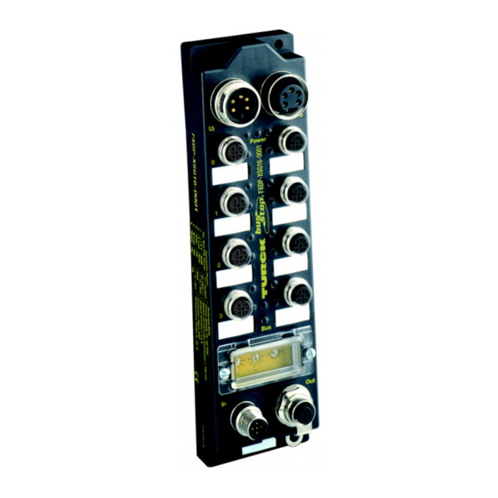
General information General information The new FXDP product family shows the following proven module properties: rugged PROFIBUS-DP module glass-fibre reinforced plastic housing fully encapsulated electronics degree of protection IP67 galvanic channel isolation to the PROFIBUS-DP short-circuit protected channels Figure 1: FXDP module Note All modules of the product family FXDP are approved for use in... -
Page 18: Product Overview
The FXDP product family Product overview Table 2: Product overview of the FXDP family User data Comment section 8 Bit IN x I per connector 16 Bit IN x I/I per connector 8 Bit OUT x O per connector 16 Bit OUT x O/O per connector 8 Bit IN, x I/I or O/O per... -
Page 19: The Service Module
Product overview The service module Besides the typical FXDP properties like the extended diagnosis, the possibility of diagnosis-data mapping into the user data as well as the comfortable M12-I/O-connection technology, the service module FXDP-XSG16-0001 provides the following additional features: Each single channel can be configured according to the applica- tion via configuration software tools (e.g. -
Page 20: Connection To Profibus-Dp
The FXDP product family Connection to PROFIBUS-DP Addressing on PROFIBUS-DP The PROFIBUS-DP address (1 to 126) is set via three decimal rotary coding switches located under a transparent protective cover. Figure 2: X 100 X 10 Setting the PROFIBUS-DP address Transmission rates The module supports transmission rates of up to 12 Mbps and adjusts automatically to the transmission speed determined by the... -
Page 21: Configuration Files
Connection to PROFIBUS-DP Configuration files The configuration files for the software link are available via the internet under www.turck.com for download purposes. The following table shows the corresponding configuration files for each single module: Table 3: Module Configuration file Configuration files FXDP-IM8-0001 TU0_ff1f.gsd... -
Page 22: Connection Possibilities
The FXDP product family Connection possibilities PROFIBUS-DP Module connection to the PROFIBUS-DP is established via two reverse-keyed M12 connectors. Figure 3: Male (IN) Female (OUT) M12x1-connector for connection to 1 =N.N. 1 = 5 VDC PROFIBUS-DP 2 = A line 2 = A line 3 = GND 3 = GND... -
Page 23: In-/ And Outputs
Connection possibilities In-/ and outputs The module is equipped throughout with 5-pole metal M12- connectors for connection of the sensor/actuator level. Note For the pin assignment, please refer to the wiring diagrams in the module-specific chapters of the manual. D300720 0905 - FXDP... -
Page 24: General Technical Data
The FXDP product family General technical data Technical data Table 4: Power supply General technical Operational voltage U 24 VDC (18 ... 30 VDC) data of FXDP modules Load voltage U 24 VDC (18 ... 30 VDC) Internal current < 70 mA consumption (via U Connections nickel-plated brass connectors... - Page 25 General technical data Shock resistance test according to EN 60068-2-27 according to EN 61000-6-2, EN 61000-6-4 Approval for use in to EN 50014/2000, Zone 2 EN 50021/2000 / É II 3 G EEx nA IIC T4 X Temperature range – Operating 0 °C to +55 °C temperature (+32 °F to +131 °F)
-
Page 26: Dimension Drawings
The FXDP product family Dimension drawings Figure 5: FXDP module- dimensions ø 5,4 60,4 FXDP-CSG88-0001 210,5 220,5 LED indications Table 5: Color Meaning FXDP green communication with PROFIBUS- LED indications DP running no communication to PROFIBUS-DP Power < 18 VDC green and U within the operating range... -
Page 27: Diagnosis
Diagnosis Diagnosis These modules combine the advantages of channel diagnostics - as known from the PDP series - with the favorable compact housing dimensions of the FLDP series. Output diagnostics are effective for each channel, whereas the sensor supply is monitored separately for each connector. Diagnostic data are also transferred to the PROFIBUS-DP and the respective status is indicated via LEDs on the module individually for each channel. - Page 28 The FXDP product family 1-14 D300720 0905 - FXDP...
-
Page 29: Digital Input Modules
Digital Input Modules Digital input module, 8-channel............2 FXDP-IM8-0001...................2 – Wiring diagram ..................3 – Technical data ..................3 – Parameterization ..................4 – Diagnosis ....................5 Digital input module, 16-channel............6 FXDP-IM16-0001..................6 – Wiring diagram ..................7 – Technical Data ..................7 – Parameterization ..................8 –... -
Page 30: Digital Input Module, 8-Channel
Digital Input Modules Digital input module, 8-channel FXDP-IM8-0001 ® The busstop input station FXDP-IM8-0001 is a modular PROFIBUS-DP slave in a compact housing design. The module is suited for connection of up to eight 2/3 wire pnp sensors or mechanical contacts. Figure 6: FXDP-IM8-0001 D300720 0905 - FXDP... -
Page 31: Technical Data
Digital input module, 8-channel Wiring diagram Figure 7: 3 (–) BU Wiring diagram 4 ( ) BK 1 (+) BN Technical data Table 6: Type FXDP-IM8-0001 Technical data Configuration file TU0_ff1f.gsd FXDP-IM8-0001 Inputs (8) 2/3 wire pnp sensors Supply (via UB) 24 VDC (18 ... -
Page 32: Parameterization
Digital Input Modules Parameterization Table 7: Param.- Parameter Meaning parameter data Byte assignment 0 to 6 Standard DP parameters according to PROFIBUS- DP standard 7 to 9 Standard DPV1 parameters according to PROFIBUS- DP standard 10 to 13 defined: not parameterizable 1 input per connector 14 to 16 reserved... -
Page 33: Diagnosis
Digital input module, 8-channel Diagnosis diagnostic messages in the diagnosis telegram: Table 8: Diagnostic message Meaning Diagnostic Short circuit Channel wise diagnosis for short circuits messages at the connected sensor Undervoltage Operating voltage U < 18 VDC. diagnosis in process data image Table 9: Input Bit 7 Bit 6 Bit 5 Bit 4 Bit 3 Bit 2 Bit 1 Bit 0... -
Page 34: Digital Input Module, 16-Channel
Digital Input Modules Digital input module, 16-channel FXDP-IM16-0001 ® The busstop input station FXDP-IM16-0001 is a modular PROFIBUS-DP slave in a compact housing design. The module is suited for connection of up to sixteen 2/3 wire pnp sensors or mechanical contacts. Figure 8: FXDP-IM16-0001 D300720 0905 - FXDP... -
Page 35: Wiring Diagram
Digital input module, 16-channel Wiring diagram Figure 9: 3 BU – Wiring diagram 4 BK 5 PE 1 BN + 2 WH 3 BU – Technical Data Table 10: Type FXDP-IM16-0001 technical Data Configuration file TU1_ff1f.gsd FXDP-IM16-0001 Inputs (16) 2/3 wire pnp sensors Supply (via UB) 24 VDC (18 ... -
Page 36: Parameterization
Digital Input Modules Parameterization Table 11: Param.- Parameter Meaning parameter data Byte assignment 0 to 6 Standard DP parameters according to PROFIBUS-DP standard 7 to 9 Standard DPV1 parameters according to PROFIBUS-DP standard 10 to 13 defined: not parameterizable 2 inputs per connector 14 to 16 reserved D300720 0905 - FXDP... - Page 37 Digital input module, 16-channel Diagnosis diagnostic messages in diagnosis telegram: Table 12: Diagnostic message Meaning Diagnostic Short circuit Channel wise diagnosis for short circuits messages at the connected sensor Undervoltage Operating voltage U < 18 V. diagnosis in process data image Table 13: Input Bit 7 Bit 6 Bit 5 Bit 4 Bit 3 Bit 2 Bit 1 Bit 0...
- Page 38 Digital Input Modules 2-10 D300720 0905 - FXDP...
-
Page 39: Digital Output Modules
Digital Output Modules Digital output module, 8-channel ............2 FXDP-OM8-0001..................2 – Wiring diagram ..................3 – Technical data ..................3 – Parameterization ..................4 – Diagnosis ....................5 Digital output module, 16-channel ............ 6 FXDP-OM16-0001..................6 – Wiring diagram ..................7 – Technical data ..................7 – Parameterization ..................8 –... -
Page 40: Digital Output Module, 8-Channel
Digital Output Modules Digital output module, 8-channel FXDP-OM8-0001 ® The busstop output station FXDP-OM8-0001 is a modular PROFIBUS-DP slave in a compact housing design. Up to eight DC actuators with a maximum output current of 1.4 A per output can be connected. Figure 10: FXDP-OM8-0001 D300720 0905 - FXDP... -
Page 41: Wiring Diagram
Digital output module, 8-channel Wiring diagram Figure 11: 4 (+) BK Wiring diagram 3 (–) BU Technical data Type FXDP-OM8-0001 Table 14: Technical data Configuration file TU2_ff1f.gsd FXDP-OM8-0001 Outputs (8) DC-actuators Load supply (via U 24 VDC (18 ... 30 VDC) Output current 1,4 A, short-circuit protected (ON period = 50 %) -
Page 42: Parameterization
Digital Output Modules Parameterization Table 15: Param.- Parameter Meaning Parameter data Byte assignment 0 to 6 Standard DP parameters according to PROFIBUS- DP standard 7 to 9 Standard DPV1 parameters according to PROFIBUS- DP standard 10 to 13 defined: not parameterizable 1 output per connector 14 and reserved... - Page 43 Digital output module, 8-channel Diagnosis diagnostic messages in diagnosis telegram: Table 16: Diagnostic message Meaning Diagnostic Short circuit Channel wise diagnosis for short circuits messages at the connected actuator. Undervoltage Operation voltage U missing or < 18 VDC Load voltage missing Load voltage U missing or <...
-
Page 44: Digital Output Module, 16-Channel
Digital Output Modules Digital output module, 16-channel FXDP-OM16-0001 ® The busstop output station FXDP-OM16-0001 is a modular PROFIBUS-DP slave in a compact housing design. Up to sixteen DC actuators with a maximum output current of 1.4 A per output can be connected. Figure 12: FXDP-OM16-0001 D300720 0905 - FXDP... -
Page 45: Wiring Diagram
Digital output module, 16-channel Wiring diagram Figure 13: 4 BK + 5 PE Wiring diagram 2 WH + 3 BU – Technical data Table 18: Type FXDP-OM16-0001 Technical data Configuration file TU3_ff1f.gsd FXDP-OM16-0001 Outputs (16) DC-actuators Load supply (via U 24 VDC (18 ... -
Page 46: Parameterization
Digital Output Modules Parameterization Table 19: Param.- Parameter Meaning Parameter data Byte assignment 0 to 6 Standard DP parameters according to PROFIBUS- DP standard 7 to 9 Standard DPV1 parameters according to PROFIBUS- DP standard 10 to 13 defined: not parameterizable 2 Outputs per connector 14 and reserved... - Page 47 Digital output module, 16-channel Diagnosis diagnostic messages in the diagnosis telegram Table 20: Diagnostic message Meaning Diagnostic Short circuit Channel wise diagnosis for short circuits messages at the connected actuator. Undervoltage Operation voltage U missing or < 18 VDC Load voltage missing Load voltage U missing or <...
- Page 48 Digital Output Modules 3-10 D300720 0905 - FXDP...
-
Page 49: Digital Hybrid Modules
Digital Hybrid Modules Digital hybrid module, 2 x 8-channel, I/I or O/O per connector ..2 FXDP-IOM88-0001 ..................2 – Wiring diagrams ..................3 – Technical data ..................4 – Parameterization ..................5 – Diagnosis ....................5 Digital combined module, 2 x 8-channel, I/O per connector ..... 7 FXDP-CSG88-0001 ..................7 –... -
Page 50: Digital Hybrid Module, 2 X 8-Channel, I/I Or O/O Per Connector
Digital Hybrid Modules Digital hybrid module, 2 x 8-channel, I/I or O/O per connector FXDP-IOM88-0001 ® The busstop input/output station FXDP-IOM88-0001 is a modular PROFIBUS-DP slave in a compact housing design. Up to eight 2/3 wire pnp sensors and eight DC actuators with a maximum output current of 1.4 A per output can be connected. -
Page 51: Wiring Diagrams
Digital hybrid module, 2 x 8-channel, I/I or O/O per connector Wiring diagrams Figure 15: 3 BU – Wiring diagrams 4 BK 5 PE 1 BN + 2 WH 3 BU – 5 PE 4 BK + 2 WH + 3 BU –... -
Page 52: Technical Data
Digital Hybrid Modules Technical data Table 22: Type FXDP-IOM88-0001 Technical data Configuration file TU4_ff1f.gsd FXDP-IOM88-0001 Inputs (8) 2/3 wire pnp sensors Supply (via U 24 VDC (18 ... 30 VDC) Supply current < 120 mA per connector, short-circuit protected Switching threshold 2 mA/4 mA OFF/ON Switching current... -
Page 53: Parameterization
Digital hybrid module, 2 x 8-channel, I/I or O/O per connector Parameterization Table 23: Param.- Parameter Meaning Parameter data Byte assignment 0 to 6 Standard DP parameters according to PROFIBUS- DP standard 7 to 9 Standard DPV1 parameters according to PROFIBUS- DP standard 10 and 00, 00... - Page 54 Digital Hybrid Modules diagnosis in process data image Table 25: Input Bit 7 Bit 6 Bit 5 Bit 4 Bit 3 Bit 2 Bit 1 Bit 0 process data Byte 0 C3P2 C3P4 C2P2 C2P4 C1P2 C1P4 C0P2 C0P4 Output Bit 7 Bit 6 Bit 5 Bit 4 Bit 3 Bit 2 Bit 1 Bit 0 Byte 0 C7P2 C7P4 C6P2 C6P4 C5P2 C5P4 C4P2 C4P4...
-
Page 55: Digital Combined Module, 2 X 8-Channel, I/O Per Connector
Digital combined module, 2 x 8-channel, I/O per connector Digital combined module, 2 x 8-channel, I/O per connector FXDP-CSG88-0001 ® The busstop input/output station FXDP-CSG88-0001 is a modular PROFIBUS-DP slave in a compact housing design. Up to eight 2/3 wire pnp sensors and eight DC actuators with a maximum output current of 1.4 A per output can be connected. -
Page 56: Wiring Diagram
Digital Hybrid Modules Wiring diagram Figure 17: 3 (–) BU Wiring diagram 4 ( ) BK 1 (+) BN D300720 0905 - FXDP... -
Page 57: Technical Data
Digital combined module, 2 x 8-channel, I/O per connector Technical data Table 26: Type FXDP-CSG88-0001 Technical data Configuration file TU5_ff1f.gsd FXDP-CSG88-0001 Inputs (8) 2/3 wire pnp sensors Supply (via U 24 VDC (18 ... 30 VDC) Supply current < 120 mA per connector, short-circuit protected Switching threshold 2 mA/4 mA... -
Page 58: Parameterization
Digital Hybrid Modules Parameterization Table 27: Param.- Parameter Meaning Parameter data Byte assignment 0 to 6 Standard DP parameters according to PROFIBUS- DP standard 7 to 9 Standard DPV1 parameters according to PROFIBUS- DP standard 10 and 88, 88 Pin 2 of the connectors is not parameterizable defined a output, pin 4 as input. - Page 59 Digital combined module, 2 x 8-channel, I/O per connector diagnosis in process data image Table 29: Input Bit 7 Bit 6 Bit 5 Bit 4 Bit 3 Bit 2 Bit 1 Bit 0 process data Byte 0 C7P4 C6P4 C5P4 C4P4 C3P4 C2P4 C1P4 C0P4 Output Bit 7 Bit 6 Bit 5 Bit 4 Bit 3 Bit 2 Bit 1 Bit 0 Byte 0...
- Page 60 Digital Hybrid Modules 4-12 D300720 0905 - FXDP...
-
Page 61: Universal Service Module
Universal Service Module FXDP-XSG16-0001 ................2 The service module ..................2 Block diagram .....................4 Wiring diagrams ..................5 Technical data .....................6 Configuration options ..................7 Parameterization ..................8 Diagnosis.....................9 – Diagnostic messages in the diagnosis telegram ........9 – Diagnosis in the process data image ............10 D300720 0905 - FXDP... -
Page 62: Fxdp-Xsg16-0001
Universal Service Module FXDP-XSG16-0001 ® The busstop input/output station FXDP-XSG16-0001 is a modular PROFIBUS-DP slave in a compact housing design. The module is equipped with sixteen channels, which can be configured differently depending on the specific application requirements. Up to sixteen 2/3 wire pnp sensors or sixteen DC actuators with a maximum output current of 1.4 A per output can be connected. - Page 63 FXDP-XSG16-0001 Figure 18: FXDP-XSG16-0001 D300720 0905 - FXDP...
-
Page 64: Block Diagram
Universal Service Module Block diagram Figure 19: Input Block diagram Invert. Input FXDP-XSG16-0001 Diag. Input Output U (24 V) Input Invert. Input Output A Wire-break detection via external bridge between PIN 2 and U . Only realizable with the parameterization of PIN 2 as “Diag. -
Page 65: Wiring Diagrams
FXDP-XSG16-0001 Wiring diagrams Figure 21: Connection of 2 actuators: Wiring diagrams 4 BK + 5 PE 2 WH + 3 BU – Connection of 2 sensors: 3 BU – 5 PE 4 BK 1 BN + 2 WH 3 BU – Combinations of sensor and actuator: 3 (–) BU 4 ( ) BK... -
Page 66: Technical Data
Universal Service Module Technical data Table 30: Type FXDP-XSG16-0001 Technical data Configuration file TU6_ff1f.gsd FXDP-XSG16-0001 Inputs (configurable) ((n) 2/3 wire pnp sensors (n = 0...16) Supply (via U 24 VDC (18 ... 30 VDC) Supply current < 120 mA per connector, short-circuit protected Switching threshold 2 mA/4 mA... -
Page 67: Configuration Options
FXDP-XSG16-0001 Configuration options Table 31: ´Configuration options for the universal service module User data Comment area 8 Bit IN x I per connector 16 Bit IN x I/I per connector 8 Bit OUT x O per connector 16 Bit OUT x O/O per connector 8 Bit IN, x I/I bzw. -
Page 68: Parameterization
Universal Service Module Parameterization Table 32: Param.- Parameter Meaning Parameter data Byte assignment 0 to 6 Standard DP parameters according to PROFIBUS- A The parame- DP standard terization of the in- put as diagnostic 7 to 9 Standard DPV1 parameters according to PROFIBUS- input can only be DP standard realized if the in-... -
Page 69: Diagnostic Messages In The Diagnosis Telegram
FXDP-XSG16-0001 Diagnosis Diagnostic messages in the diagnosis telegram Table 33: Diagnostic message Meaning diagnostic Short circuit Channel wise diagnosis for short circuits messages at the connected sensor/ actuator. Wire-break Indication of a wire-break in the sensor- / or actuator line (please read the following „Note“). -
Page 70: Diagnosis In The Process Data Image
Universal Service Module Diagnosis in the process data image Table 34: Input Bit 7 Bit 6 Bit 5 Bit 4 Bit 3 Bit 2 Bit 1 Bit 0 process data Byte 0 C3P2 C3P4 C2P2 C2P4 C1P2 C1P4 C0P2 C0P4 Byte 1 C7P2 C7P4 C6P2 C6P4 C5P2 C5P4 C4P2 C4P4 Output... -
Page 71: Connection To A Siemens Plc S7
Connection to a Siemens PLC S7 General ....................2 Reading- in the GSD File..............3 – Reading-in the GSD files before starting the software ......3 – Reading-in the GSD files after starting the software .......3 Selecting the FXDP Modules as Slaves ..........5 Configuring the FXDP modules ..............6 Diagnostic messages in the process image..........7 Parameterization of the FXDP modules .......... -
Page 72: General
Connection to a Siemens PLC S7 General The software „SIMATIC Manager“ V 5.1 with Service Pack 6 from Siemens is used to configure the connection of FXDP modules with the Siemens S7 PLC. The CPU used in the S7 in the following example was a CPU 315-2AF02-0AB0 with firmware version 3. -
Page 73: Reading- In The Gsd File
Reading- in the GSD File Reading- in the GSD File The GSD files for FXDP must be read into the software before you can begin with the initial configuration. There are two procedures possible for reading-in the files: Reading-in the GSD files before starting the software Copy the GSD files „TUx_ff1f.gsd“... - Page 74 Connection to a Siemens PLC S7 Select the GSD file from the corresponding source directory. Figure 22: Selection of the GSD files from the corresponding source directory The GSD files are listed as separate entries in the hardware catalog following correct installation. Figure 23: FXDP modules in the hardware...
-
Page 75: Selecting The Fxdp Modules As Slaves
Selecting the FXDP Modules as Slaves Selecting the FXDP Modules as Slaves To insert a FXDP module as a slave, select the required entry from the hardware catalog. Figure 24: Inserting a FXDP module as a slave D300720 0905 - FXDP... -
Page 76: Configuring The Fxdp Modules
Connection to a Siemens PLC S7 Configuring the FXDP modules After the selection of a module as modular slave, the function of the module has to be defined. Please choose one of the module’s configuration options from the hardware catalog. Figure 25: Configuration of the slave... -
Page 77: Diagnostic Messages In The Process Image
Selecting the FXDP Modules as Slaves Diagnostic messages in the process image The FXDP modules offer the possibility to map the diagnosis data into the process image. This can be achieved by adding the function „Add On: Diagnosis in I/O-Data“ to the module’s configuration. Figure 26: Add on: Diagnosis in I/O-Data... -
Page 78: Parameterization Of The Fxdp Modules
Connection to a Siemens PLC S7 Parameterization of the FXDP modules If parameterizable modules have been chosen, the slave properties can be opened with a double click on the respective module. Figure 27: Parameterizing a FXDP module D300720 0905 - FXDP... -
Page 79: Diagnosis Evaluation On A S7-Plc
Diagnosis evaluation on a S7-PLC Diagnosis evaluation on a S7-PLC In the following example, a S7 PLC with the CPU 315-2AF02-0AB0, firmware version 3, is used for diagnosis evaluation. Note A correct diagnosis-data evaluation cannot be guaranteed if S7 PLCs with older hard- or firmware-version are used. The diagnosis evaluation of the FXDP modules can be done either via the online diagnosis in the hardware configurator of the SIMATIC software or via the Siemens function block FB125. - Page 80 Connection to a Siemens PLC S7 The button „Hex Format...“ opens the window „Diagnosis in Hexa- decimal Format“ which shows the module’s entire diagnosis tele- gram. Figure 28: Module information Note The software „SIMATIC Manager“ only interprets the standardized error codes in the online diagnosis. 6-10 D300720 0905 - FXDP...
- Page 81 Diagnosis evaluation on a S7-PLC The following example shows a simulated failure in the load voltage supply (U ). The software can not interpret the diagnostic message „No encoder voltage or load voltage“ (error code 17), because it is not standardized. Figure 29: Error code 17 (not standardized)
-
Page 82: Diagnosis Via Function Block Fb125
Connection to a Siemens PLC S7 Diagnosis via function block FB125 The following description shows the diagnosis with function block 125 version V4.5. You can download the actual version of the func- tion block directly from the Siemens homepage. Note Please read the function block’s description from Siemens for all in- formation about structure and handling of FB 125. - Page 83 Diagnosis evaluation on a S7-PLC The following example shows a diagnostic message with error code 6 („Wire break“) at station 22, channel 0. Figure 31: VAT125 with diag- nostic message The function block FB125 transmits the diagnostic messages to higher-level operating panels which interpret the error codes and display them as plain text diagnosis.
- Page 84 Connection to a Siemens PLC S7 6-14 D300720 0905 - FXDP...
-
Page 85: Appendix
Appendix Declaration of conformity ..............2 D300720 0905 - FXDP... -
Page 86: Declaration Of Conformity
Appendix Declaration of conformity Figure 32: Declaration of conformity D300720 0905 - FXDP... -
Page 87: Glossary
Glossary Acknowledge Acknowledgment of a signal received. Active metal component Conductor or conducting component that is electrically live during operation. Address Identification number of, e.g. a memory position, a system or a module within a network. Addressing Allocation or setting of an address, e. g. for a module in a network. Analog Infinitely variable value, e. - Page 88 Glossary Bus system for data exchange, e. g. between CPU, memory and I/O levels. A bus can consist of several parallel cables for data transmission, addressing, control and power supply. Bus cycle time Time required for a master to serve all slaves or stations in a bus system, i. e. reading inputs and writing outputs.
- Page 89 Electronic Industries Association – association of electrical companies in the United States. Electrical components All objects that produce, convert, transmit, distribute or utilize electrical power (e. g. conductors, cable, machines, control devices). Electromagnetic compatibility – the ability of an electrical part to operate in a specific environment without fault and without exerting a negative influence on its environment.
- Page 90 Glossary Ground reference Potential of ground in a neutral grounding device. Unlike earth whose potential is always zero, it may have a potential other than zero. Acronym for Electronic Device Data Sheet which contains standardized PROFIBUS DP station descriptions. They simplify the planning of the DP master and slaves.
- Page 91 Intelligent modules Intelligent modules are modules with an internal memory, able to transmit certain commands (e. g. substitute values and others). Load value Predefined value for the counter module with which the count process begins. Lightning protection All measures taken to protect a system from damage due to overvoltages caused by lightning strike.
- Page 92 Glossary Multi-master mode Operating mode in which all stations in a system communicate with equal rights via the bus. NAMUR German acronym for an association concerned with standardizing measure- ment and control engineering. NAMUR initiators are special versions of the two-wire initiators.
- Page 93 PROFIBUS-DP address Each PROFIBUS-DP module is assigned an explicit PROFIBUS-DP address, with which it can be queried by the master. PROFIBUS-DP master The PROFIBUS-DP master is the central station on the bus and controls access of all stations to PROFIBUS. PROFIBUS-DP slave PROFIBUS-DP slaves are queried by the PROFIBUS-DP master and exchange data with the master on request.
- Page 94 Glossary Root-connecting Creating a new potential group using a power distribution module. This allows sensors and loads to be supplied individually. RS 485 Serial interface in accordance with EIA standards, for fast data transmission via multiple transmitters. Serial Type of information transmission, by which data is transmitted bit by bit via a cable.
- Page 95 To ground Connection of a conductive component with the grounding connection via a grounding installation. Topology Geometrical structure of a network or the circuitry arrangement. UART Universal Asynchronous Receiver/Transmitter. UART is a logic circuit which is used to convert an asynchronous serial data sequence to a parallel bit sequence or vice versa.
- Page 96 Glossary 8-10 D300720 0905 - FXDP...
- Page 97 Index addressing ........1-6 online diagnosis ......6-9 operating files ........ 1-8 output modules, digital ....3-1 bus termination ......1-6 parameterization ......6-8 configuration files ......1-7 plain-text diagnosis ..... 1-13 prescribed Use ......0-3 process image ....... 6-7 Declaration of conformity ....
- Page 98 TURCK WORLD-WIDE HEADQUARTERS GERMANY Hans Turck GmbH & Co. KG Witzlebenstraße 7 D-45472 Mülheim an der Ruhr P. O. Box 45466 Mülheim an der Ruhr Phone (+49) (208) 4952-0 (+49) (208) 4952-2 64 E-Mail turckmh@turck.com D300720 0905 *D300782ßß0704* Subject to change without notice...
Need help?
Do you have a question about the FXDP Series and is the answer not in the manual?
Questions and answers