
Related Manuals for Daikin Skyline OAH003GDAC


Summary of Contents for Daikin Skyline OAH003GDAC
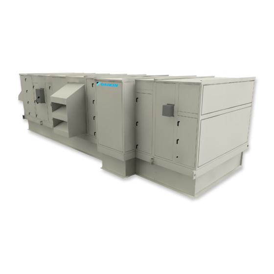
- Page 1 Installation and Maintenance Manual IM 777-17 Group: Applied Air Systems Part Number: IM 777 Date: December 2019 Skyline Outdoor Air Handler ®...
-
Page 2: Table Of Contents
Curb Mounting and Unit Leveling ....6 Daikin Fan Array ......34 Assembling Sections . -
Page 3: Introduction
021, 025, 030, 035, 040, 050, 065, 080, 085, 090 D = Motor downstream of belt-drive plenum fan F = Motor on inline fan Vintage of Daikin air handling unit G = Motor downstream of direct-drive plenum fan Unit type/coil position... -
Page 4: Unit Storage
• Reduce belt tension by at least 50% or remove the belts. unit resulting from improper storage will not be covered Remove belts if they will be subjected to temperatures by Daikin Applied. exceeding 85°F to avoid deterioration. • Ensure no moisture, debris, or minerals are on the unit •... -
Page 5: Mechanical Installation
eChanICal nsTallaTIon eChanICal nsTallaTIon Service Clearances Rigging In addition to providing adequate space around the unit for WARNING piping coils and drains, access to at least one side of the unit Use all lifting points. Improper lifting can cause severe is always required to allow for regular service and routine personal injury and property damage. -
Page 6: Curb Mounting And Unit Leveling
770. For a provided with a connection splice joint attached to the cabinet copy, contact your local Daikin representative or visit www. which seals against the gasket of the frame channel on the DaikinApplied.com. - Page 7 eChanICal nsTallaTIon 3. Ensure the splice collar lines up with the opening in the Figure 8: Sections with Vestibules mating section. Use clamps or threaded rod at the base lifting lugs to pull the sections closer. Be careful to not damage them.
- Page 8 eChanICal nsTallaTIon d. For certain high pressure low leakage units, Figure 11: Splice Collar Alignment use the provided section joining plates to fasten sections together. Space them as shown in Figure 9. Using the provided ¼"-14 × 1" self tapping screws, drill screw the joining plates into the frame channel on each section, keeping unit sections tight together.
-
Page 9: Panels, Frame Channels, And Doors
eChanICal nsTallaTIon Panels, Frame Channels, and Fan Section Doors Doors WARNING Sharp edges and coil surfaces are a potential injury hazard. Panel Removal Avoid contact. To remove a side or top panel, remove the flat head Torx 30 NOTE: Opening fan section doors requires using a 17 mm fasteners along the sides of the panel. -
Page 10: Field Mounting Junction Boxes And Other Components
eChanICal nsTallaTIon Field Mounting Junction Boxes and Injected-Foam Insulated Panels Other Components Skyline air handlers now are furnished with double-wall, injected-foam insulated panels. Foam panels are stronger, For field mounting 4" × 4" or smaller junction boxes to the more rigid, and lighter than panels with fiberglass insulation. standard panel exterior, use a minimum quantity of four, 3/16"... - Page 11 eChanICal nsTallaTIon AAF HEPA Filters without Prefilters Figure 17: Leg Extensions and Latches without Prefilters STEP 1: At the inside corner of each frame are 4 tabs, 2 per side. Place a leg extension over the 4 tabs as shown in Figure 18, then pull back on the leg extension locking it into place (Figure...
- Page 12 eChanICal nsTallaTIon STEP 2: Insert the HEPA filter into the HEPA Holding Frame. STEP 3: Place a latch so that it overlaps the leg extension, The HEPA should be installed with the gasket side of the as shown in Figure 23.
- Page 13 eChanICal nsTallaTIon AAF HEPA Filters with Prefilters STEP 4: Once all four corner latches have been tightened within 1/4" of the leg extension coupling, complete the Follow previous steps 1-2, then continue straight to step 5. installation by tightening each corner until the latch and leg extension coupling meet.
- Page 14 eChanICal nsTallaTIon Figure 30: Tighten Cap Screw to 1/4" of the Coupling Repeat the process with all remaining filters working from the bottom to the top. Figure 32: Properly Installed HEPA Filter Figure 31: Tighten until Latch and Coupling Meet Once all four corners have been tightened the HEPA filter should now be properly seated and sealed.
- Page 15 eChanICal nsTallaTIon STEP 8: To complete the installation, add the appropriate prefilter latches to the prefilter holding frame. Once latches are installed, place the prefilter in the frame, secure with the latches and the installation is complete. Repeat with all remaining prefilters and frames. Figure 33: Installation of Prefilter into Frame Figure 34: Completed Assembly www.DaikinApplied.com...
-
Page 16: Duct Connections
eChanICal nsTallaTIon Duct Connections Use flexible connectors on the outlet and inlet duct connections Figure 36: Suggested Flashing over Top Panels and Sides of all units. Do not position down flow fans over air ducts that of Units are routed down into the building. Use a discharge plenum Flashing when bottom connections are necessary (Figure... -
Page 17: Dampers And Hoods
eChanICal nsTallaTIon Dampers and Hoods Mounting Actuators Side dampers may be provided in the mixing box and CAUTION economizer sections of units. When dampers are provided, Maximum damper rotation is 70°. Maximum shaft torque is access to the damper drive shaft is recommended internally 205 inches/pound. -
Page 18: Isolation Dampers For Multiple Fans
eChanICal nsTallaTIon Piping Vestibules Face and Bypass Section Mounting Internal and external face and bypass sections are mounted The Skyline air handler has 2 options for piping vestibules. The together using the instructions for horizontal components curb ready base unit has a factory installed vestibule and the and do not require additional instruction. - Page 19 eChanICal nsTallaTIon Field-Installed Vestibule Figure 41: Typical Vestibule WARNING Use all lifting points. Improper lifting can cause severe personal injury and property damage. CAUTION Lifting points may not be symmetrical to the center of gravity of the unit. Ballast or unequal cable lengths maybe required. SPLICE COLLAR The unit can be shipped with an optional field installed vestibule.
- Page 20 eChanICal nsTallaTIon Figure 42: Caulking the Vestibule Roof Cap Figure 43: Detail of Mounting Screws UNIT SPLICE COLLAR SCREW UNIT TO VESTIBULE SPLICE DETAIL Figure 44: Additional Caulking IM 777-18 • SKYLINE OUTDOOR AIR HANDLER www.DaikinApplied.com...
-
Page 21: Piping And Coils
eChanICal nsTallaTIon Piping and Coils When designing and installing piping: Steam Coils • Follow applicable piping design, sizing, and installation Piping (see Figure information in ASHRAE handbooks. • Observe all local codes and industry standards. • Steam supply and steam return connections typically are male NPT iron pipe and are labeled on the end panel of •... - Page 22 — The base of a Skyline unit has a secondary drip shield installed below every panel that drains potential • Daikin strongly recommends 5JA, 8JA, 5RA and 8RA coils. moisture to the outside frame trough. It is critical that • Supply 5 psi steam to coils at all times.
- Page 23 eChanICal nsTallaTIon Figure 46: Piping Arrangements Control valve Float and modulating Check Valve Strainer Gate Valve thermostatic trap two position High Pressure (over 25 psi) 5TA, 8TA, or 5HA coils. Conden- 5GA or 8GA coils. Note that the addition of a vacuum breaker to sate is lifted to overhead return main permit the coil to drain during...
- Page 24 eChanICal nsTallaTIon Water Heating Coils Drain Pan Traps Run drain lines and traps full size from the drain pan CAUTION connection. Install drain pan trap to allow condensate to drain Improper installation, use, or maintenance of water heating freely. On both blow-through and draw-through units, the trap coils can cause equipment damage.
-
Page 25: Internal Isolation Assembly Adjustment
eChanICal nsTallaTIon Internal Isolation Assembly Adjustment On units with internally isolated fan and motor assemblies, the For models 040 through 090 with housed fans, the isolators assemblies are secured for shipment. with a tie-down at each should be at equal height during fan operation (6"). Center the point of isolation. - Page 26 eChanICal nsTallaTIon Figure 50: Removing “Motor Behind” Shipping Brackets Figure 51: Removing “Motor Beside” Shipping Brackets Figure 52: Plenum Fan Typical Shipping Brackets Shipping hold-down nut and bolt Remove and discard - 4 places Shipping bracket - Remove and discard - 4 places IM 777-18 •...
-
Page 27: Oshpd Seismic Anchoring/Mounting
eChanICal nsTallaTIon OSHPD Seismic Anchoring/Mounting For seismic stability of the unit, additional anchoring and Figure 54: Unit with Base Frame Welded mounting procedures are required. The anchoring options and corresponding spectral response acceleration are given in Table 6. Holes in the Vision/Skyline base frame are to be field drilled. -
Page 28: Electrical Installation
For variable frequency drives,or other energy storing components that have been furnished and mounted by either Daikin, or by others, refer to the specific manufacturer’s literature for allowable waiting periods for discharge of capacitors. Verify capacitors have been discharged using an appropriate voltmeter. - Page 29 leCTrICal nsTallaTIon Wiring Penetrations • Control wiring—access to the VFD is through the fan cabinet access door for single fans. Provide shielded • Seal any panel penetrations for wiring or conduit per the cable only as described in the VFD manual provided with panel cutting procedure instructions within this document.
-
Page 30: Operation Guidelines
peraTIon uIdelInes peraTIon uIdelInes Startup Checks Before Starting the Unit WARNING CAUTION Rotating fan. Can use severe injury or death. Before servicing Equipment damage due to loose fasteners represents fans, lock out and tag out power. improper start-up and equipment abuse. It is not covered by the warranty. -
Page 31: Vfd Setup
peraTIon uIdelInes VFD Setup Fan Wheel Alignment Fans ordered with VFDs that were factory installed are setup Figure 57: Wheel-to-Inlet Tunnel Relationship—Airfoil Type and tested prior to shipment. Prior to starting the fan(s), double Fan Wheels (Housed) check the VFD settings according to the recommendations in the VFD manual. - Page 32 peraTIon uIdelInes Table 8: Wheel-to-Inlet Funnel Relationship—Forward Figure 60: Wheel-to-Inlet Funnel Relationship—40 to 60 Curved Type Fan Wheels Belt-Drive Plenum Fan Cross Section Reference Diameter – in . in . (mm) Unit Sizes 003 to 035 9 × 4 0.25 (6.35) 9 ×...
- Page 33 peraTIon uIdelInes Figure 61: Wheel-to-Inlet Funnel Relationship—In-line Table 12: Wheel to Inlet Funnel Relationship—Direct-Drive Fans Class II fans Fan Size – in . Overlap – in . (mm) 0.25 (6.35) 0.25 (6.35) 0.25 (6.35) 0.38 (9.65) 0.38 (9.65) 0.41 (10.41) 0.45 (11.43) 0.50 (12.7) 0.55 (13.97)
-
Page 34: Setscrews
peraTIon uIdelInes Setscrews Table 15: Bearing Collar and Wheel Hub Set Screw Torque Setscrews on MPQ fan wheels must be installed using a (All Fans Except Class II Plenum Fans) calibrated torque wrench to the value listed below, ±5%. The fasteners must be periodically checked to satisfy agency Minimum torque requirements for components on rotating machinery. -
Page 35: Daikin Fan Array
Daikin supplied VFD. Care should be taken when programing and synchronizing the drives in the Daikin Fan Array such that all fans turn at the same speed. Fans running at unequal speeds can produce vibration and could stall a fan. Definition of fan numbering is... - Page 36 peraTIon uIdelInes Optional Piezometer Ring Airflow Measurement Device Non-Standard Density Method Piezometer rings are available as an option on direct drive plenum fans to measure airflow though the fan. The device The following equation is used to measure the flow for non- consists of a piezometer ring mounted in the throat of the standard density: funnel and a static pressure tap mounted near the inlet of the...
- Page 37 Optional Transducer for Piezometer Rings Table 18: DDPL Factors for Free and Ducted Inlet – Non-Standard Density Method, Daikin Piezo Ring A transducer is available for Piezometer rings. Factory mounting locations for the fan transducer is shown in Figure 65...
- Page 38 peraTIon uIdelInes Figure 66: Direct-drive Plenum Fan Installation Route tube (DCX56) from the high pressure tap of the transmitter to the outer face of the funnel or the inlet panel. Secure tubing to the fan assembly using cable-tie mount (DCX52) and Location may vary depending on fan size.
-
Page 39: Daikin Ec Fan Array
Figure 68 shows a single fan control box. There will The Daikin EC Fan Array is made of an impeller, EC motor, and be 1 MMP per fan in the array to connect each fan to. inverter. It is installed as an assembly, and in the event of failure, the entire assembly must be replaced. - Page 40 peraTIon uIdelInes Figure 69: Single Fan Control Panel - High Voltage Wiring Figure 72: EC Fan Array (in red); Low Voltage Wiring (in blue) Fan Installed with (4) ½" Hex AVK Bolts Figure 70: Required Molex Plug and Crimp Terminals Figure 71: Molex Plug Crimp Terminal Locations IM 777-18 •...
- Page 41 peraTIon uIdelInes Figure 73: Control Signal Figure 76: YY Figure 74: High Voltage Wiring Figure 77: Block-Off Plate Installation Figure 75: Gen 2 BLOCK-OFF PLATE KIT FAN SIZE PART NO 910199478 910199479 910311272 910311272 910311273 Figure 78: Gen 3 www.DaikinApplied.com IM 777-18 •...
- Page 42 peraTIon uIdelInes Optional Piezometer Point Airflow Measurement Device Figure 79: Piezometer Transducer A Piezometer point is an option with EC fans to measure airflow through the fan. The device consists of a piezometer point mounted in the throat of the funnel and a static pressure tap mounted near the inlet of the funnel.
-
Page 43: Operating Limits
peraTIon uIdelInes Operating Limits Do not exceed the operating limits in Table 22 through Table 26. A fan wheel operated beyond the rpm and temperature limits shown can suffer permanent distortion or fracture. The resulting unbalance can cause severe unit vibration Table 22: Unit Sizes 003 to 035 Fan Operating Limits Forward curved—housed... -
Page 44: Fan Vibration Levels
peraTIon uIdelInes Fan Vibration Levels Vibration Causes 1. Wheel imbalance. Each unit as shipped is trim balanced to operate smoothly. To provide satisfactory operation after shipping and installation, a. Dirt or debris on wheel blades. use the accepted industry guidelines for field balancing fans. b. -
Page 45: Gas Furnace
The Daikin furnace modules have a maximum inlet pressure of 13.5” w.c. Installer is responsible for supplying a pressure The high limit switch is an automatic reset switch and it opens regulator if required. - Page 46 Standard Efficiency Models Where condensate drains are located outside a heated space The Daikin outdoor air handling unit is equipped with an or in a space where temperatures may fall below freezing, outdoor air hood to supply adequate combustion air. The unit the drain line must be protected.
-
Page 47: Wiring/Controls
urnaCe Wiring/Controls Single Furnace Recovery from Lockout 1. If the thermostat (controller) is still calling for heat one 2-Stage Controls hour after a lockout occurs, the control will automatically reset and initiate a call for heat sequence. Sequence 2. The ignition control may also be manually reset, by When system is powered up 24 VAC will be applied to the turning the thermostat (controller) down and back up to ignition control (IC) terminals 24VAC/GND. - Page 48 urnaCe Figure 80: HM/HD Series – SN Control (Staged Control) 115 VAC IGNITION CONTROL DRAFT INDUCER Not Used 40VA External Safety ROLL OUT ROLL OUT Interlocks T' STAT SWITCH HI LIMIT SWITCH (2) Factory APS-1 Jumper AIR SWITCH -HI T-Stat (PSW) Series 5 Ignition Control FLAME...
- Page 49 urnaCe 5:1 Modulating Furnace Sequence 15. Provided the High Air Switch (APS-2) contacts are closed, with analog inputs between 5.1 and 10.0 VDC When system is powered, 24 VAC will be applied to the ignition the EXA Valve will modulate the gas input between mid- control (IC) across terminals 24VAC/GND, to the SC40 (Blue fire and high fire.
- Page 50 urnaCe Recovery from Lockout 1. If the thermostat (controller) is still calling for heat one ERROR CODES - Red Flashes Error Definition Error Type hour after a lockout occurs, the control will automatically • 1 flash, then pause - No flame in trial time Lockout reset and initiate a call for heat sequence.
- Page 51 urnaCe 10:1 Modulating Furnace Sequence 11. For analog inputs from 0.5 to 2.5 VDC, the ID Fan will run at low speed and LED’s PWR (Blue), MOD (Green) Standby Mode R1 (Red) are lit. (Note: Green (AFS) LED may be lit 1.
- Page 52 urnaCe 22. Section B operation continues until the analog input Recovery from Lockout signal to the SC30SM2A control drops below 4.8 VDC. At 1. If the thermostat (controller) is still calling for heat one this point the SC30SM-2A R2 relay opens (Red R2 LED hour after a lockout occurs, the control will automatically OFF).
- Page 53 urnaCe Figure 82: HM/HD Series - MB Control (10:1) 115 VAC 240T6T15 SRTN IGNITION CONTROL 7062-6797 SC30-SM2AN DRAFT NDUCER XFMR 1 WHT (Com) 40 VA Customer ROLL OUT Interlocks SWITCH (A) T' STAT (See Note) HI LIMIT (1) APS-1 (Low) Factory Jumper HI LIMIT (2) Series 5 Ignition Control...
-
Page 54: Rack Furnace
urnaCe Rack Furnace HD Rack assemblies employ a Vernier staging modulating Figure 83: Typical Rack Distribution Wiring control that modulate gas flow up and down to a lead modulating furnace to account for varying heat requirements during operation. Additional slave furnaces have two stage controls which are activated by relays on the staging control to meet higher heating requirements. - Page 55 urnaCe Figure 85: EF (Drum and Tube) High Efficiency Furnace BK/W Provide Disconnect BLOWER and Overload 120V/1/60 Protection as BK/W 120 V required. Alarm Output 120V 120V Dry Alarm Contact Relay BK/W SCEBM-2 BLOWER Level Sw. SCEBM-2 120V On / Off Switch OR/W SCEBM-2...
- Page 56 urnaCe Figure 86: Rack Furnace Wiring Diagram 10 VDC Analog Input from Building Management System System Heat Enable Contact * Customer safety interlocks include VCB Panel Air flow proving switch, Customer Safety Interlocks* Terminals auxiliary manual reset limit and gas pressure GRN/YEL switch (if required) 115V Line...
-
Page 57: Direct Fired Heater
urnaCe Direct Fired Heater Installation WARNING The following recommendations are not intended to Improper installation, adjustment, alteration, service, or supplant any requirements of federal, state, or local codes maintenance can cause property damage, injury, or death. having jurisdiction. This equipment shall be installed Read the installation, operating and maintenance instructions and wired in accordance with regulations of the National thoroughly before installing or servicing this equipment. - Page 58 urnaCe Air Stream Velocity Burner shut down 1. Shut of main disconnect DANGER 2. Close main gas valve. Improper installation, adjustment, alteration, service, or maintenance can cause property damage, injury, or death. Restarting the gas heat after short shut down Read the installation, operating and maintenance instructions thoroughly before installing or servicing this equipment.
-
Page 59: Operation Of The Basic Pco Carel Controller
T i m e : 0 0 : 0 0 : 0 0 D a t e : 0 0 : 0 0 : 0 0 L o a d i n g ..urnaCe s e t t i m e / d a t e : P C O : 0 0 0 Operation of the Basic pCO Carel Controller... - Page 60 urnaCe 10. This will take you to the screen above that should be 15. To view the alarms; and will have the cursor on the hour, use the up ▲ or a. Push the Alarm Bell button and then scroll down ▼...
-
Page 61: Bacnet Points
urnaCe BACnet Points Table 29: Analog Variables BMS Address Description Read/Write Variable name Burner Cmd Signal to burner Burner_cmd command to VAV dampers BurnerDamperCmd Customer Burner Cmd input Signal Burner_cmd_in pco board temp pcoTemp Table 30: Integer Variables BMS Address Description Direction Variable name... -
Page 62: Service And Maintenance
Ball Bearing Lubrication lubrication schedule, see Table 33. For applications that are not in the range of the table, contact Daikin. CAUTION Bearing overheating potential. Can damage the equipment. CAUTION Do not over-lubricate bearings. Use only a high grade mineral The tables below state general lubrication recommendations grease with a 200°F safe operating temperature. -
Page 63: Fan Drive
ervICe and aInTenanCe Fan Drive Table 34: Recommended Fan Re-lubrication Grease Charge WARNING Shaft Size – in . (mm) Oz (g) Before servicing lock out and tag out all power to the 1/2 to 3/4 (20) 0.03 (0.85) unit . Fans or belts cause severe personal injury or death. 7/8 to 1-3/16 (25-30) 0.10 (2.84) 1-1/4 to 1-1/2 (35-40) - Page 64 ervICe and aInTenanCe VM and VP Variable Pitch Key Type LVP Variable Speed Sheaves Sheaves Mounting Mounting 1. Slide sheave on motor shaft so that the side of the sheave with setscrew A is next to the motor when 1. Mount all sheaves on the motor or driving shaft with the setscrew A is in the hub or barrel of the sheave.
- Page 65 ervICe and aInTenanCe MVP Variable Speed Sheaves Adjusting 1. Slack off belt tension if belts have been installed. Mounting 2. Loosen setscrews D. 1. Verify both driving and driven sheaves are in alignment 3. Loosen but do not remove capscrews E. and the shafts are parallel.
- Page 66 ervICe and aInTenanCe Table 35: Screw Torque Values Hollow-head set screws only Flat-head Socket-head cap screws Nominal socket screws Lengths equal or greater than dia . For lengths (L) less than dia . screw size (dia—thds/in) Seating torque Seating torque Seating torque Seating torque Seating torque...
-
Page 67: Fan Drive Belt Adjustment
ervICe and aInTenanCe Fan Drive Belt Adjustment Figure 93: Drive Belt Adjustment WARNING Belt span Moving belt and fan can cause severe personal injury or Deflection = death. During installation and filter maintenance: • Verify that the belt and fan guards on plenum fan units are always in place. -
Page 68: Front Load Filter Option
ervICe and aInTenanCe Front Load Filter Option Filter Gauges Front loaded filter options require that the filters be removed Filter gauges indicate pressure drop for installed filters. If and replaced from inside the unit. prefilters are present, the gauge will indicate the pressure drop for both pre-and final filters To remove filters, rotate the wire clips. -
Page 69: Coils
NOTE: Carefully read instructions for mixing antifreeze 8. Replace panels and fasteners. solution used. Some products have a higher freezing point in their natural state when mixed with water. Daikin is not responsible for the freezing of coils. www.DaikinApplied.com IM 777-18 • SKYLINE OUTDOOR AIR HANDLER... - Page 70 ervICe and aInTenanCe Removing the Fan Section Figure 96: Single Coil Top Installation/Removal For plenum fan assemblies, the entire fan cabinet may need to be removed to replace the entire fan assembly depending on the length of the fan section. In some cases, the fan section is not long enough for the assembly to fit out the side of the cabinet.
- Page 71 ervICe and aInTenanCe Removing Stacked Coils Removing and Installing Staggered Coils NOTE: Top and bottom stacked coils are held together with Staggered coils have two banks of coils positioned a few steel plate and screws on one side and drain trough inches apart in the direction of airflow.
-
Page 72: Parts, Service And Warranty Procedure
Replacement Parts Warranty When writing to Daikin for service or replacement parts, refer Consult your local Daikin Applied representative for warranty to the model number and serial number of the unit stamped on details. To find your local Daikin sales representative, go to the serial plate attached to the unit. - Page 73 Air Handling Equipment Warranty Registration Form To comply with the terms of Daikin Applied Warranty, complete and return this form within 10 days to the Warranty Department of Daikin Applied. Check, test, and start procedure for air handling units with or without heat recovery and roof mounted air handlers.
-
Page 74: Check, Test And Warranty Registration Form
heCk esT and arranTy eGIsTraTIon AHU Equipment Warranty Registration Form (continued) Select Yes or No. If not applicable to the type of unit, select N/A. I. INITIAL CHECK A. Is any shipping damage visible? ........Yes B. - Page 75 heCk esT and arranTy eGIsTraTIon AHU Equipment Warranty Registration Form (continued) Select Yes or No. If not applicable to the type of unit, select N/A. G. Voltage at return fan motor(s): ....1–2_____________ V 2–3 _____________ V 1–3 _____________ V *Fan array units only .
- Page 76 heCk esT and arranTy eGIsTraTIon AHU Equipment Warranty Registration Form (continued) Select Yes or No. If not applicable to the type of unit, select N/A. IV. ELECTRIC HEAT A. Electrical heat service corresponds to unit nameplate? ......Yes Volts _____________ Hertz _____________ Phase _____________ B.
- Page 77 heCk esT and arranTy eGIsTraTIon AHU Equipment Warranty Registration Form (continued) Select Yes or No. If not applicable to the type of unit, select N/A. VIII. Design Flow calibration A. Verify power is supplied to the MicroTech III unit controller ......Yes B.
- Page 78 AAH.Wty_WAR_forms@daikinapplied.com Please fill out the Daikin Applied “Quality Assurance Survey Report” and list any additional comments that could affect the operation of this unit; e.g., shipping damage, failed components, adverse installation applications, etc. If additional comment space is needed, write the comment(s) on a separate sheet, attach it to the Survey Report and return it to the Warranty Department of Daikin Applied with the completed Equipment Warranty Registration form.
-
Page 79: Quality Assurance Survey
Poor 10. How would you rate the overall quality of the product? Excellent Good Fair Poor 11. How does the quality of Daikin Applied products rank in relation to competitive products? Excellent Good Fair Poor Comments _______________________________________________________________________________________ Please list any additional comments which could aff ect the operation of this unit; i.e., shipping damage, failed components, adverse installation applications, etc. If additional comment space is needed, write the comment(s) on a separate sheet, attach the sheet to this completed Quality Assurance Survey Report, and return it to the Warranty Department with the completed preceding “Equipment Warranty Registration Form”. - Page 80 Daikin Applied Training and Development Now that you have made an investment in modern, efficient Daikin equipment, its care should be a high priority. For training information on all Daikin HVAC products, please visit us at www.DaikinApplied.com and click on Training, or call 540-248-9646 and ask for the Training Department.
Need help?
Do you have a question about the Skyline OAH003GDAC and is the answer not in the manual?
Questions and answers