Table of Contents
Advertisement
Quick Links
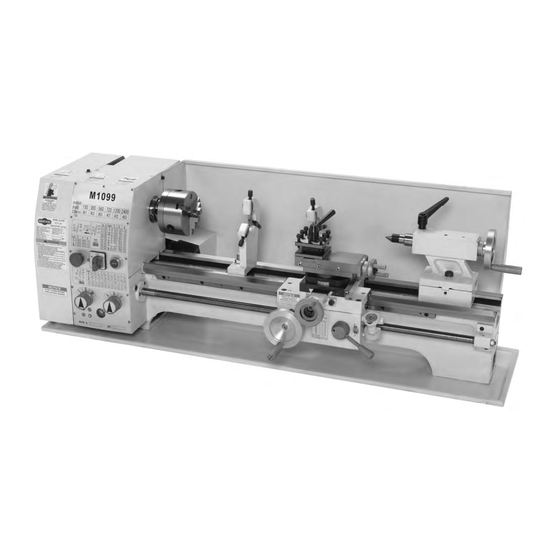
Model M1099
***IMPORTANT UPDATE***
Applies to Models Mfd. Since 03/18
and Owner's Manual Revised 05/12
Phone #: (360) 734-3482 • Tech Support: tech-support@shopfox.biz • Web: www.shopfox.biz
We made the following changes to this machine since the manual was printed:
Updated Apron breakdown and list.
•
Aside from the information contained in this update, all other content in the owner's manual is
applicable and MUST be read and understood for your own safety.
IMPORTANT: Keep this update with the owner's manual for future reference. If you have any further
questions, contact our Technical Support.
Revised Apron Handwheel Parts
136V2
145
144
143
133V2
REF
PART #
DESCRIPTION
133V2 XM1099133V2 HANDWHEEL V2.03.18
134V2 XM1099134V2 SET SCREW M6-1 X 12
136V2 XM1099136V2 GEAR SHAFT V2.03.18
143
XM1099143
PLATE SPRING
144
XM1099144
GRADUATED DIAL
145
XM1099145
ROLL PIN 5 X 12
146
XM1099146
KEY 3 X 3 X 12
COPYRIGHT © APRIL, 2018 BY WOODSTOCK INTERNATIONAL, INC.
WARNING: NO PORTION OF THIS MANUAL MAY BE REPRODUCED IN ANY SHAPE OR FORM WITHOUT
#9052KB
READ THIS FIRST
146
134V2
THE WRITTEN APPROVAL OF WOODSTOCK INTERNATIONAL, INC.
Printed in China
Advertisement
Table of Contents

Related Manuals for Shop fox M1099


Summary of Contents for Shop fox M1099
- Page 1 READ THIS FIRST Model M1099 ***IMPORTANT UPDATE*** Applies to Models Mfd. Since 03/18 and Owner's Manual Revised 05/12 Phone #: (360) 734-3482 • Tech Support: tech-support@shopfox.biz • Web: www.shopfox.biz We made the following changes to this machine since the manual was printed: Updated Apron breakdown and list.
- Page 2 MODEL M1099 10" x 26" BENCHTOP LATHE OWNER'S MANUAL (FOR MODELS MANUFACTURED SINCE 8/07) Phone: (360) 734-3482 • Online Technical Support: tech-support@shopfox.biz COPYRIGHT © FEBRUARY, 2007 BY WOODSTOCK INTERNATIONAL, INC., REVISED APRIL, 2011 (BLTS) WARNING: NO PORTION OF THIS MANUAL MAY BE REPRODUCED IN ANY SHAPE OR FORM WITHOUT THE WRITTEN APPROVAL OF WOODSTOCK INTERNATIONAL, INC.
- Page 3 This manual provides critical safety instructions on the proper setup, operation, maintenance, and service of this machine/tool. Save this document, refer to it often, and use it to instruct other operators. Failure to read, understand and follow the instructions in this manual may result in fire or serious personal injury—including amputation, electrocution, or death.
-
Page 4: Table Of Contents
Table of Contents INTRODUCTION ........2 MAINTENANCE ........32 Woodstock Technical Support ....2 Basic Maintenance ......32 Machine Specifications ......3 General Lubrication ......32 Identification ........5 Belt Adjustment or Replacement .... 34 SAFETY ..........6 SERVICE ..........35 Standard Machinery Safety Instructions ..6 Troubleshooting ......... -
Page 5: Introduction
INTRODUCTION Woodstock Technical Support Your new SHOP FOX Model M1099 Benchtop Lathe has been specially designed to provide many years ® of trouble-free service. Close attention to detail, ruggedly built parts and a rigid quality control program assure safe and reliable operation. -
Page 6: Machine Specifications
Spindle Threads....................8 Number of Spindle Speeds................... 6 Spindle Speeds............150, 300, 560, 720, 1200, 2400 RPM Spindle Type..................Threaded Spindle Bearings................Tapered Roller Tailstock Info Tailstock Quill Travel................2-1/2 in. Tailstock Taper................... MT#3 Model M1099 Machine Specifications, Page 1 of 3... - Page 7 Assembly Time ....................1 Hour Features Hardened and Ground V-Ways Chip Tray Included Back Splash Full Featured Carriage and Apron Assemblies Provide Super Accurate Cuts and Finishes Long Bed Accommodates 26 in. Between Cuts Model M1099 Machine Specifications, Page 2 of 3...
-
Page 8: Identification
Model M1099 (Mfg Since 8/07) Identification A. Emergency Stop Button L. Chip Tray B. Motor Direction Selector Knob M. Thread Dial C. Power ON Push Button N. Half Nut Lever D. 3-Jaw Chuck O. Cross Feed Handwheel E. Steady Rest P. -
Page 9: Safety
Model M1099 (Mfg Since 8/07) SAFETY SAFETY For Your Own Safety, Read Manual Before Operating Machine The purpose of safety symbols is to attract your attention to possible hazardous conditions. This manual uses a series of symbols and signal words intended to convey the level of importance of the safety messages. - Page 10 Model M1099 (Mfg Since 8/07) APPROVED OPERATION. Untrained operators STABLE MACHINE. Unexpected movement during can be seriously hurt by machinery. Only operations greatly increases the risk of injury allow trained or properly supervised people and loss of control. Verify machines are to use machine.
-
Page 11: Additional Safety Instructions For Lathes
Model M1099 (Mfg Since 8/07) Additional Safety Instructions for Lathes CLEARING CHIPS. Metal chips can easily cut bare SAFE CLEARANCES. Workpieces that crash into skin—even through a piece of cloth. Avoid clear- other components on the lathe may throw dan- ing chips by hand or with a rag. -
Page 12: Electrical
Model M1099 (Mfg Since 8/07) ELECTRICAL Circuit Requirements This machine must be connected to the correct size and type of power supply circuit, or fire or electrical damage may occur. Read through this section to determine if an adequate power supply circuit is available. If a correct... -
Page 13: Grounding Requirements
Model M1099 (Mfg Since 8/07) Grounding Requirements This machine MUST be grounded. In the event of certain The machine must be properly set up types of malfunctions or breakdowns, grounding provides before it is safe to operate. DO NOT a path of least resistance for electric current to travel—in connect this machine to the power order to reduce the risk of electric shock. -
Page 14: Setup
Model M1099 (Mfg Since 8/07) SETUP Unpacking This machine has been carefully packaged for safe Some hardware/fasteners on the inven- transportation. If you notice the machine has been tory list may arrive pre-installed on damaged during shipping, please contact your authorized the machine. -
Page 15: Machine Placement
Model M1099 (Mfg Since 8/07) Machine Placement Cleaning Machine • Workbench Load: This machine distributes The bed and other unpainted parts of your lathe a heavy load in a small footprint. Some are coated with a waxy grease that protects them from corrosion during shipment. -
Page 16: Test Run & Break-In
Model M1099 (Mfg Since 8/07) Test Run & Break-In The purpose of the test run is to make sure the lathe and safety features operate correctly before proceeding with additional setup. Make sure the half nut lever is disengaged before you start the lathe! To begin the test run &... - Page 17 Model M1099 (Mfg Since 8/07) 9. Turn the lathe OFF, disconnect power, move the drive belt to the next highest RPM and then run the lathe for 10 minutes. 10. Repeat Step 9 for the rest of the speeds, progres- sively increasing the speed.
-
Page 18: Operations
Model M1099 (Mfg Since 8/07) OPERATIONS General The Model M1099 will perform many types of operations that are beyond the scope of this manual. Many of these operations can be dangerous or deadly if performed incorrectly. The instructions in this section are written with the understanding that the operator has the necessary knowledge and skills to operate this machine. -
Page 19: Mounting Chuck Or Faceplate
Model M1099 (Mfg Since 8/07) Mounting Chuck or Spindle Lock Hole Faceplate The three-jaw scroll chuck will automatically self-center the workpiece. It has hardened steel external jaws that hold the workpiece on the outside diameter of the part. An extra set of jaws is included for holding larger workpieces on the inside diameter of the part. -
Page 20: Replacing Jaws
Model M1099 (Mfg Since 8/07) Replacing Jaws The three-jaw scroll chuck has removable hardened steel jaws (Figure 9). The outside of the jaws are used to hold the workpiece from the outer diameter. Numbered from 1–3, the jaws must be used in the match- ing numbered jaw guides (see Figure 10). -
Page 21: Four-Jaw Chuck
Model M1099 (Mfg Since 8/07) Four-Jaw Chuck To install the four-jaw chuck, do these steps: Refer to the Mounting Chuck or Faceplate procedures on when Page 16 to mount the four-jaw chuck. machining heavy eccentric workpieces; Objects thrown To hold a workpiece in the four-jaw chuck, do these from a lathe can cause seri- ous injury or death. -
Page 22: Faceplate
Model M1099 (Mfg Since 8/07) Faceplate The faceplate can be used to turn non-cylindrical parts or for off-center turning by clamping the workpiece to the faceplate. when machining heavy eccentric Refer to the Mounting Chuck or Faceplate procedures on workpieces; Objects thrown Page 16 to mount the faceplate. -
Page 23: Tailstock
Model M1099 (Mfg Since 8/07) Tailstock The tailstock (Figure 15) can be used to support workpieces with a live or dead center. The lathe can drill Quill Lock Lever or bore holes in the center of a part with a drill bit held by the tailstock. -
Page 24: Cutting Shallow Tapers With Tailstock
Model M1099 (Mfg Since 8/07) Cutting Shallow Tapers with Tailstock To setup the tailstock to cut tapers, do these steps: Quill Lock Lever 1. Loosen the tailstock lock nut. 2. Using a 4mm hex wrench, alternately loosen and tighten the left and right offset adjustment set... -
Page 25: Aligning Tailstock
Model M1099 (Mfg Since 8/07) Aligning Tailstock The tailstock is factory aligned with the headstock. We recommend that you take the time to ensure that the tailstock is aligned to your own desired tolerances. To align the tailstock, do these steps: 1. -
Page 26: Centers
Model M1099 (Mfg Since 8/07) Centers A dead center can be used in the tailstock and lathe spindle to support workpieces. When used in this man- ner, make sure to keep the dead center tip and workpiece Failure to keep dead center point well lubricated to prevent tip galling. -
Page 27: Steady Rest
Model M1099 (Mfg Since 8/07) Steady Rest The steady rest serves as a support for long shafts. The Finger Adjustment steady rest can should be placed along the ways where the Lock Nut Knob most support can be given to the workpiece and still allow for all of your intended lathe operations. -
Page 28: Compound Rest
Model M1099 (Mfg Since 8/07) Compound Rest The compound rest is used to cut tapers on parts or to set the proper infeed angle when threading. It may also be used to cut specific lengths longitudinally, when set parallel to the spindle axis. -
Page 29: Manual Feed Handwheels
Model M1099 (Mfg Since 8/07) Manual Feed Handwheels You can manually move the cutting tool around the workpiece using the three handwheels shown in Figure Compound Rest Handwheel Compound Rest Handwheel The compound rest handwheel controls the position of Cross Slide the cutting tool relative to the workpiece. -
Page 30: Determining Correct Spindle Rpm
Model M1099 (Mfg Since 8/07) Determining Correct Spindle RPM To determine the correct spindle RPM, do these steps: Use the table in Figure 28 to determine the cutting Failure to follow RPM and feed rate speed required for the material of your workpiece. -
Page 31: Spindle Rpm
Model M1099 (Mfg Since 8/07) Spindle RPM This lathe has six possible spindle speeds. Shown in Figure 30 is an example of how you would use the chart to get a spindle RPM of 150. when machining heavy eccentric To set the spindle RPM, do these steps: workpieces;... -
Page 32: Power Feed Rate
Model M1099 (Mfg Since 8/07) Power Feed Rate Use these steps to learn how to setup your lathe for a power feed operation. The example in Figure 32 shows lathe setup for a power feed rate of 0.012". Remember, Feed rate is based on spindle RPM. Pay... -
Page 33: Inch Threads
Model M1099 (Mfg Since 8/07) Inch Threads Use these steps to learn how to setup your lathe for inch threading. The example in Figure 34 shows lathe setup for cutting 64 TPI (Teeth Per/Inch) thread. During threading keep your hand on... -
Page 34: Metric Threads
Model M1099 (Mfg Since 8/07) Metric Threads Use these steps to learn how to setup your lathe for 6. Move the lash adjuster so the gear metric threading. The example in Figure 35 shows lathe backlash is between 0.003" to 0.008", setup for cutting a metric thread pitch of 0.45mm. -
Page 35: Maintenance
Model M1099 (Mfg Since 8/07) MAINTENANCE Basic Maintenance Regular periodic maintenance of your lathe will ensure optimum performance. Make a habit of inspecting your machine each time you use it. Gearbox Oil Fill Check for the following conditions and repair or replace when necessary: •... - Page 36 Model M1099 (Mfg Since 8/07) Figure 39. Apron and carriage ball oilers. Figure 40. Leadscrew and tailstock ball oilers. -33-...
-
Page 37: Belt Adjustment Or Replacement
Model M1099 (Mfg Since 8/07) Belt Adjustment or Replacement ENTANGLEMENT HAZARD! Disconnect this lathe from power and wait until all spinning parts have come to a complete stop before you access the belt and pulleys. Otherwise you may be severely injured! To replace or adjust the V-belts, do these steps: 1. -
Page 38: Service
Model M1099 (Mfg Since 8/07) SERVICE Troubleshooting This section covers the most common problems and corrections with this type of machine. WARNING! DO NOT make any adjustments until power is disconnected and moving parts have come to a complete stop! Motor &... - Page 39 Model M1099 (Mfg Since 8/07) Troubleshooting Operation and Work Results SYMPTOM POSSIBLE CAUSE CORRECTIVE ACTION Lathe vibrates 1. Workpiece is unbalanced. 1. Reinstall workpiece so it is centered. excessively. 2. Worn or broken gear present. 2. Inspect gears and replace if necessary.
-
Page 40: Cross Slide Backlash Adjustment
Model M1099 (Mfg Since 8/07) Cross Slide Backlash 1 of 3 Cross Slide Gib Adjustment Adjustment Points Cross Slide Backlash is the amount of play found in a lead screw. It Backlash can be found by turning the cross slide handwheel in one Adjustment direction, then turning the handwheel the other direction. -
Page 41: Electrical Component Connections
Model M1099 (Mfg Since 8/07) Electrical Component Connections Figure 46. Motor rotary switch and ON power switch (SA and SB1). Figure 48. Motor rotary switch and emergency stop switch (SA and SB2). Figure 49. Motor start contactor. Figure 47. External motor capacitors. -
Page 42: Wiring Diagram
Model M1099 (Mfg Since 8/07) Figure 51. Motor connection detail. Figure 50. Motor data plate. Wiring Diagram LEGEND C1: Capacitor KM: Magnetic Contactor 110V C2: Capacitor SB1: ON Push Button Switch SA: Motor Direction Rotary Switch SB2: Emergency Stop Push Button Switch... -
Page 43: Parts
Model M1099 (Mfg Since 8/07) PARTS Spindle and Drive Belt 23 24 -40-... - Page 44 Model M1099 (Mfg Since 8/07) Spindle and Drive Belt Parts REF PART # DESCRIPTION REF PART # DESCRIPTION XM1099001 CONTROL PANEL FACE XPSB50M CAP SCREW M5-.8 X 10 XPS17M PHLP HD SCR M4-.7 X 6 XPW02M FLAT WASHER 5MM XPSB06M CAP SCREW M6-1 X 25 XM1099031 SPINDLE SHAFT XPW03M FLAT WASHER 6MM XM1099032 COGGED BELT 263L XM1099007 COMPRESSION SPRING XP6001 BALL BEARING 6001 XM1099008 CLAMP XM1099034 COGGED PULLEY XPSB06M CAP SCREW M6-1 X 25...
-
Page 45: Apron
Model M1099 (Mfg Since 8/07) Apron -42-... -
Page 46: Apron Parts
Model M1099 (Mfg Since 8/07) Apron Parts REF PART # DESCRIPTION REF PART # DESCRIPTION 101 XPRP19M ROLL PIN 4 X 14 122 XM1099122 POINTER 102 XM1099102 HALF NUT 123 XM1099123 SHAFT 103 XPRP59M ROLL PIN 5 X 12 124 XPK39M KEY 3 X 3 X 10 104 XM1099104 GEAR SHAFT 125 XPSB83M CAP SCREW M6-1 X 55 105 XM1099105 GEAR 126 XM1099126 THREAD DIAL BODY... -
Page 47: Tool Holder And Compound Rest
Model M1099 (Mfg Since 8/07) Tool Holder and Compound Rest 217A 217A-1 PART # DESCRIPTION PART # DESCRIPTION XM1099201 COMPOUND REST 217A XPSS19M SET SCREW M8-1.25 X 30 XM1099202 SWIVEL BASE 217A-1 XPN03M HEX NUT M8-1.25 XM1099203 XM1099218 HANDLE XM1099204 CLAMPING RING XM1099219 HANDLE HUB XM1099205 GRADUATED DIAL XM1099220 TOOL REST XM1099206 BARREL NUT XM1099221 RUB SPACER... -
Page 48: Tailstock
Model M1099 (Mfg Since 8/07) Tailstock REF PART # DESCRIPTION REF PART # DESCRIPTION 301 XM1099301 TAILSTOCK QUILL 314 XPSS21M SET SCREW M8-1.25 X 25 302 XM1099302 LEAD SCREW 315 XM1099315 HANDLE 303 XM1099303 BUSHING 316 XM1099316 OFFSET SCALE PLATE 304 XM1099304 HANDWHEEL SCALE PLATE 317 XM1099317 LEADSCREW KEY 305 XM1099305 HANDWHEEL 318 XPLN05M LOCK NUT M10-1.5... -
Page 49: Bed And Leadscew
Model M1099 (Mfg Since 8/07) Bed and Leadscew REF PART # DESCRIPTION REF PART # DESCRIPTION 401 XM1099401 BED 409 XM1099409 SPLASH GUARD 402 XM1099402 RACK 410 XM1099410 STUD M10-1.5 X 35 403 XPSB33M CAP SCREW M5-.8 X 12 411 XPN02M HEX NUT M10-1.5 404 XM1099404 LEAD SCREW 412 XPSS44M SET SCREW M8-1.25 X 40 405 XM1099405 BRACKET 413 XPW01M FLAT WASHER 8MM... -
Page 50: Steady Rest And Follow Rest
Model M1099 (Mfg Since 8/07) Steady Rest and Follow Rest 507 508 REF PART # DESCRIPTION REF PART # DESCRIPTION XM1099501 STEADY REST CASTING XPN02M HEX NUT M10-1.5 XM1099502 FINGER XM1099511 FOLLOW REST CASTING XM1099503 T-BOLT M6-1 XM1099512 FINGER XPLW03M LOCK WASHER 6MM XM1099503 T-BOLT M6-1 XPN01M HEX NUT M6-1 XM1099514 ADJUSTING SCREW XM1099506 ADJUSTING SCREW XPN01M HEX NUT M6-1... -
Page 51: Motor And Electrical
Model M1099 (Mfg Since 8/07) Motor and Electrical 611-5 611-3 611-4 611-6 611-1 611-2 REF PART # DESCRIPTION PART # DESCRIPTION XM1099601 CABINET 611-2 XM1099611-2 FAN COVER XPSB06M CAP SCREW M6-1 X 25 611-3 XM1099611-3 START CAPACITOR 150MFD/125VAC XPLW03M LOCK WASHER 6MM 611-4 XM1099611-4 RUN CAPACITOR 20MFD/400VAC XM1099604 COVER 611-5 XM1099611-5 CAPACITOR COVER W/CAP XM1099607 STRAIN RELIEF NUT... -
Page 52: Gearbox Diagram A
Model M1099 (Mfg Since 8/07) Gearbox Diagram A -49-... - Page 53 Model M1099 (Mfg Since 8/07) Gearbox Diagram A Parts REF PART # DESCRIPTION REF PART # DESCRIPTION 701 XPSS01M SET SCREW M6-1 X 10 XM1099723 GEAR 104T 702 XM1099702 BUSHING XPW03M FLAT WASHER 6MM 703 XM1099703 PLASTIC DRIVE GEAR (60-TOOTH)
-
Page 54: Gearbox Diagram B
Model M1099 (Mfg Since 8/07) Gearbox Diagram B 802 803 847 848 844 845 -51-... - Page 55 Model M1099 (Mfg Since 8/07) Gearbox Diagram B Parts REF PART # DESCRIPTION REF PART # DESCRIPTION XM1099801 PLUG XM1099828 SHAFT XM1099802 O-RING XM1099829 GEAR 33T XM1099803 BUSHING XM1099830 GEAR 30T XM1099804 CLUSTER GEAR 30-36-33T XM1099831 GEAR 35T XPK133M KEY 4 X 4 X 50 XM1099832 FLANGE XM1099806 SHAFT XPSB01M CAP SCREW M6-1 X 16 XM1099807...
-
Page 56: Cross Feed And Carriage
Model M1099 (Mfg Since 8/07) Cross Feed and Carriage 920V2 907 908 -53-... - Page 57 Model M1099 (Mfg Since 8/07) Cross Feed and Carriage Parts PART # DESCRIPTION REF PART # DESCRIPTION XM1099901 SADDLE XM1099921 DOWEL PIN 902V2 XM1099902V2 CROSS SLIDE V2.08.07 XPSS34M SET SCREW M5-.8 X 16 XM1099903 XPN06M HEX NUT M5-.8 XM1099904 CROSS SLIDE NUT...
-
Page 58: Warranty
Woodstock International, Inc. will repair or replace, at its expense and at its option, the Shop Fox machine or machine part, which in normal use has proven to be defective, provided that the original owner returns the product prepaid to a Shop Fox factory service center with proof of their purchase of the product within two years, and provides Woodstock International, Inc. - Page 59 Model M1099 (Mfg Since 8/07)
- Page 60 Fold along dotted lIne place stamp Here Woodstock international inc. p.o. box 2309 bellingham, Wa 98227-2309 Fold along dotted lIne tape along edges--please do not staple...
- Page 61 High Quality Machines and Tools Woodstock International, Inc. carries thousands of products designed to meet the needs of today's woodworkers and metalworkers. Ask your dealer about these fine products:...
Need help?
Do you have a question about the M1099 and is the answer not in the manual?
Questions and answers