Table of Contents
Advertisement
Advertisement
Table of Contents

Related Manuals for Shop fox SHOP FOX M1049


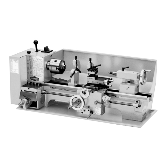
Summary of Contents for Shop fox SHOP FOX M1049
-
Page 3: Table Of Contents
Table of Contents Contents INTRODUCTION ....................3 SAFETY ......................8 ELECTRICAL ....................12 SETUP ......................14 LATHE OPERATIONS ..................18... - Page 4 MAINTENANCE ....................34 SERVICE ......................36 PARTS ......................43 WARRANTY ..................... 61...
-
Page 5: Introduction
INTRODUCTION Woodstock Technical Support... - Page 6 0RWRUV 0DLQ 0DLQ 6SHFLILFDWLRQV 2SHUDWLRQ ,QIR +HDGVWRFN ,QIR 7DLOVWRFN ,QIR...
- Page 7 7KUHDGLQJ ,QIR 'LPHQVLRQV &RQVWUXFWLRQ 2WKHU 3URGXFW 'LPHQVLRQV 6KLSSLQJ 'LPHQVLRQV (OHFWULFDO 2WKHU...
- Page 8 )HDWXUHV $FFHVVRULHV...
-
Page 9: Controls And Features
Controls and Features... -
Page 10: Safety
SAFETY For Your Own Safety, Read Manual Before Operating Machine Standard Machinery Safety Instructions... -
Page 12: Additional Safety Instructions For Lathes
Additional Safety Instructions for Lathes 1. AVOIDING INJURY: 2. AVOIDING LACERATIONS AND ENTANGLEMENT: 3. USING CORRECT TOOLING: 4. ELIMINATING A PROJECTILE HAZARD: 5. SECURING A WORKPIECE: 6. CHUCK SAFETY: 7. WORKPIECE SUPPORT: 8. AVOIDING STARTUP INJURIES: 9. ELIMINATING A PROJECTILE HAZARD: 10. - Page 13 Avoiding Potential Injuries...
-
Page 14: Electrical
ELECTRICAL Circuit Requirements Full-Load Current Rating Full-Load Current Rating ......11.5 Amps Circuit Requirements for 110V Circuit Type ....110V/120V, 60 Hz, Single-Phase Circuit Size ..........15 Amps Plug/Receptacle ........NEMA 5-15... -
Page 15: Extension Cords
Grounding Requirements GROUNDED 110V 5-15 RECEPTACLE 5-15 PLUG Figure 6. For 110V Connection Figure 6 Extension Cords Minimum Gauge Size at 110V ...... 14 AWG Maximum Length (Shorter is Better)....50 ft. -
Page 16: Setup
SETUP Inventory Installed Accessories (Figure 7) Packaged Accessories (Figure 8) — — — — — — — — — — — — — — — — —... - Page 17 Machine Placement Cleaning Machine...
- Page 18 Uncrating & Lifting...
- Page 19 Test Run and Break-In To begin the test run procedure, do these steps: Figure 9. Figure 10.
-
Page 20: Lathe Operations
LATHE OPERATIONS General If at any time you are experiencing difficulties performing any opera- tion, stop using the machine! - Page 21 Chuck and Faceplate Mounting To remove and install the chuck or face plate, do these steps: Figure 11 Figure 12 Note:...
- Page 22 Replacing Jaws Figure 13 Figure 14 Note: To remove a set of jaws, do these steps: Figure 15...
- Page 23 Using the Four-Jaw Chuck To install the four-jaw chuck, do these steps: To load a workpiece in the four-jaw chuck, do these steps: Figure...
- Page 24 Using the Faceplate To install the faceplate, do these steps: To load a workpiece, do these steps: Make sure your clamping application will not fail!
-
Page 25: Figure
Using the Tailstock Figure 18 To use the tailstock, do these steps: Figure 18. -
Page 26: Figure
To setup the tailstock to cut tapers, do these steps: Figure 19 Tailstock Alignment To align the tailstock, do these steps: Figure 20 . Note:... -
Page 27: Figure
Figure 21 Figure 22... - Page 28 Using Centers To install a dead or live center into the tailstock, do these steps: Figure 23 Note: Note: To install a MT#5 dead center into the spindle, do these steps: Note:...
- Page 29 Using the Steady Rest To use the steady rest, do these steps: Figure 25 Figure Note: Using the Follow Rest Figure 26 Note:...
- Page 30 Setting Compound Slide To set the angular position, do these steps: Figure 27 Using the Tool Posts Figure 28 Figure 29...
-
Page 31: Using Manual Feed
Using Manual Feed Figure 30 Longitudinal Handwheel Cross Feed Handwheel Compound Slide Handwheel... - Page 32 Setting RPM Cutting Speeds for High Speed Steel (HSS) Cutting Tools To determine and set the needed cutting RPM, do these steps: Figure 31 Note: (Cutting Speed x 4) = RPM MACHINERY'S Diameter of Cut HANDBOOK RPM Chart Page 31 Figure 32 Figure 33 Figure 32.
- Page 33 RPM Chart...
- Page 34 Setting Power Feed Rate To set and engage the power feed, do these steps: 9 Figure 34 a" Figure 35 Note: Figure 36...
- Page 35 Threading Setup To setup for threading, do these steps: Figure 37 Figure 38 Note: Figure 39...
-
Page 36: Maintenance
MAINTENANCE General Maintenance General Cleaning General Lubrication... -
Page 38: Service
SERVICE Cross Slide Backlash Note: Figure 44 Figure 44. Note: Cross-Slide and Saddle- Gib Adjustments Figure 45 Figure 45... - Page 39 Replacing the V-Belt To replace the V-belt, do these steps: Figure 46 Figure Figure 46. Replacing the Cogged- Belt To replace the cogged-belt, do these steps: Figure 46 Figure Figure 47 Figure 47.
-
Page 40: Electrical Safety Instructions
Electrical Safety Instructions WIRING DIAGRAM COLOR KEY BLACK BLUE YELLOW LIGHT The photos and diagrams BLUE YELLOW included in this section are WHITE BROWN BLUE GREEN best viewed in color. You WHITE GREEN GRAY PURPLE can view these pages in TUR- QUOISE ORANGE... - Page 41 Wiring Diagram STOP...
-
Page 42: Troubleshooting
Troubleshooting Motor & Electrical... - Page 43 Operation and Work Results...
-
Page 45: Parts
PARTS Drive Belt PART # DESCRIPTION PART # DESCRIPTION XM1049001 BRACKET PLATE XM1049019 MOTOR PULLEY WASHER XPCAP15M CAP SCREW M5-.8 X 20 XPLW03M LOCK WASHER 6MM XM1049003 IDLER PULLEY SHAFT XPCAP06M CAP SCREW M6-1 X 25 XPW04M FLAT WASHER 10MM XM1049022 COVER PLATE XPLW06M... - Page 46 Belt Tensioner 66V2 65V2 PART # DESCRIPTION PART # DESCRIPTION XM1049053 AXLE BRACKET XM1049064 STEPPED SPRING BOLT XP6001ZZ BALL BEARING 6001ZZ 65V2 XM1049065V2 TENSIONING CAM V2.08.07 XM1049056 ROLLER 66V2 XM1049066V2 CAP SCREW M6-1 X 25 XPR03M EXT RETAINING RING 12MM XPSS20M SET SCREW M8-1.25 X 8 XPR20M...
-
Page 47: Change Gears
Change Gears PART # DESCRIPTION PART # DESCRIPTION XM1049101 BRACKET XM1049113 SPACER XM1049102 T-NUT M6-1 XPW03M FLAT WASHER 6MM XPW03M FLAT WASHER 6MM XPCAP04M CAP SCREW M6-1 X 10 XM1049104 SHAFT XPLW03M LOCK WASHER 6MM XM1049105 KEYED BUSHING XPCAP48M CAP SCREW M6-1 X 35 XM1049106 GEAR 127T XM1049118... - Page 48 Headstock 701-2 701-1 PART # DESCRIPTION PART # DESCRIPTION XM1049151 HEADSTOCK HOUSING XM1049171 GEAR 40T XM1049152 3-JAW CHUCK BACK PLATE XM1049172 GEAR 28T XM1049153 SPINDLE XPSTB006M STEEL BALL 4MM XM1049154 KEY 8 X 5 X 40 XPCAP40 CAP SCREW 3/8-16 X 3-1/4 XM1049155 GASKET XPLUBE001...
- Page 49 Quick-Change Gearbox PART # DESCRIPTION PART # DESCRIPTION XM1049201 GEARBOX HOUSING XM1049225 LOCATING PIN XM1049202 SHAFT XM1049226 COMPRESSION SPRING D9-3.5 X 37 XPK13M KEY 5 X 5 X 70 XM1049227 BUSHING XM1049204 BUSHING XM1049228 KNURLED KNOB XM1049205 GEAR 28T XM1049229 ACORN NUT M6-1 XM1049206 GEAR 26T...
- Page 50 Apron Front View Rear View 317A...
-
Page 51: Apron Parts List
Apron Parts List PART # DESCRIPTION PART # DESCRIPTION XM1049251 APRON CASTING XM1049307 HALF NUT GUIDE BAR XM1049253 WORM XPR39M EXT RETAINING RING 8MM XPK52M KEY 3 X 3 X 15 XPCAP16M CAP SCREW M4-.7 X 16 XPN04M HEX NUT M4-.7 XPSS24M SET SCREW M5-.8 X 25 XPSS22M... - Page 52 Saddle & Cross Slide PART # DESCRIPTION PART # DESCRIPTION XM1049351 SADDLE XPSS22M SET SCREW M4-.7 X 12 XM1049352 CROSS SLIDE XPN04M HEX NUT M4-.7 XM1049353 CROSS SLIDE GIB XM1049374 SADDLE GIB CLAMP XM1049354 CROSS SLIDE LEADSCREW NUT XPW03M FLAT WASHER 6MM XM1049355 CROSS SLIDE LEADSCREW XPCAP01M...
- Page 53 Compound Rest & Tool Post PART # DESCRIPTION PART # DESCRIPTION XM1049401 COMPOUND REST BODY XPW01M FLAT WASHER 8MM XM1049402 SWIVEL BASE XM1049422 COMPRESSION SPRING D13.5-5.5 X 36 XM1049403 COMPOUND REST GIB XM1049423 LEADSCREW XM1049404 CLAMPING RING XM1049424 LEADSCREW MOUNT XM1049405 GRADUATED DIAL XM1049425...
- Page 54 Tailstock PART # DESCRIPTION PART # DESCRIPTION XM1049450 COMPLETE TAILSTOCK ASSEMBLY XM1049464 TAILSTOCK BASE XM1049451 QUILL XM1049465 DOG-POINT SET SCREW M8-1.25 X 25 XM1049453 LEADSCREW XM1049466 HANDLE XM1049454 BUSHING XM1049467 HANDLE SCREW XM1049455 UPPER OFFSET PLATE XPK39M KEY 3 X 3 X 10 XM1049456 HANDWHEEL XPSS20M...
-
Page 55: Steady Rest
Steady Rest Follow Rest 501A 551A PART # DESCRIPTION 501A XM1049501A STEADY REST ASSEMBLY PART # DESCRIPTION XM1049501 STEADY REST BODY 551A XM1049551A FOLLOW REST ASSEMBLY XM1049502 STEADY REST FINGER XM1049551 FOLLOW REST BODY XM1049503 STEPPED T-BOLT XM1049502 FOLLOW REST FINGER XPLW04M LOCK WASHER 8MM XM1049503... - Page 56 PART # DESCRIPTION PART # DESCRIPTION XM1049601 XPN03M HEX NUT M8-1.25 XM1049602 RACK XPSS12M SET SCREW M6-1 X 25 XPCAP18M CAP SCREW M4-.7 X 8 XPW03M FLAT WASHER 6MM XM1049604 LONGITUDINAL LEADSCREW XPN01M HEX NUT M6-1 XM1049605 BRACKET XM1049617 SPLASH PAN XPLUBE001M TAP-IN BALL OILER 6MM XM1049618 CHIP TRAY...
- Page 57 Electrical & Tools 662-1 719A 662-3 662-2 662-6 662-4 PART # DESCRIPTION PART # DESCRIPTION XM1049651 ELECTRICAL CABINET XM1049667 STRAIN RELIEF NUT M16-1 XPCAP50M CAP SCREW M5-.8 X 10 XPS09M PHLP HD SCR M4-,7 X 6 XPLW01 LOCK WASHER 5/16 XM1049669 CAPACITOR CLIP XM1049654...
-
Page 58: Machine Labels
Machine Labels PART # DESCRIPTION PART # DESCRIPTION XM1049751 WARNINGS LABEL XM1049755 PINCH HAZARD LABEL XLABEL-04 ELECTRICITY LABEL XPPAINT-1 SHOP FOX WHITE TOUCH-UP PAINT XM1049753 TENSION LEVER NOTICE LABEL XM1049757 GROUPED WARNINGS LABEL XM1049754 MACHINE ID LABEL -56-... - Page 62 FOLD ALONG DOTTED LINE Place Stamp Here FOLD ALONG DOTTED LINE TAPE ALONG EDGES--PLEASE DO NOT STAPLE...
-
Page 63: Warranty
WARRANTY...
Need help?
Do you have a question about the SHOP FOX M1049 and is the answer not in the manual?
Questions and answers