Eaton Power Xpert PXM 4000 User And Installation Manual
Hide thumbs
Also See for Power Xpert PXM 4000:
- Quick start manual (28 pages) ,
- User and installation manual (292 pages) ,
- User manual (44 pages)
Table of Contents
Advertisement
Advertisement
Table of Contents
Troubleshooting

Subscribe to Our Youtube Channel
Related Manuals for Eaton Power Xpert PXM 4000


Summary of Contents for Eaton Power Xpert PXM 4000
- Page 1 Power Xpert PXM 4000/6000/8000 User and Installation Manual IM02601004E...
- Page 2 OBLIGATION OF EATON. THE CONTENTS OF THIS DOCUMENT SHALL NOT BE- COME PART OF OR MODIFY ANY CONTRACT BETWEEN THE PARTIES. In no event will Eaton be responsible to the purchaser or user in contract, in tort (including negligence), strict liability or otherwise for any special, indirect, incidental or...
-
Page 3: Table Of Contents
4 Introduction to Web Server Screens ........49 4.1. Overview Screen ................. 50 4.2. Trends ....................51 4.3. Energy Screen ..................54 4.4. Timeline Screen ................... 54 4.5. I/O Screen ................... 55 5 Functions on the Web Server Pages ........57 IM02601004E Page iii www.eaton.com... - Page 4 E.3. PXMCM Com 0 and Com 1 RS485 bias resistors (Terminals CM3, CM5) ................154 E.4. 24V Source Outputs CM4 & CM6 ..........156 E.5. Power Supply Card PXMPS-1 ............157 E.6. Diagnostic DIP Switch Settings ............158 IM02601004E Page iv www.eaton.com...
- Page 5 G.1. Installing Root CA with Microsoft Internet Explorer 11 ....167 G.2. Installing Root CA with Google Chrome ........170 G.3. Installing Root CA with Mozilla Firefox ......... 171 G.4. Installing Root CA with Edge ............172 H Specifications ..............177 IM02601004E www.eaton.com Page v...
- Page 6 Table of Contents IM02601004E Page vi www.eaton.com...
-
Page 7: Introduction
This technical document is the user manual for the installation, operation and unit level mainte- nance of the Eaton Power Xpert Meter. This document is intended for authorized and qualified per- sonnel who use the Power Xpert Meter. Please refer to the specific WARNINGS and CAUTIONS in this section before proceeding. -
Page 8: Applicability
PX4000/6000/8000 series refer to IB02601003E. 1.3. Applicability This manual applies to the Power Xpert Meter and display in the following configurations: Power Xpert PXM4000 Meter Power Xpert PXM6000 Meter Power Xpert PXM8000 Meter IM02601004E Page 2 www.eaton.com... - Page 9 Fast-Transient Capture 6Msps/channel (Vag, Vbg, Vcg, Vng) [PXM 8xxx] Symmetrical Components [PXM6xxx, PXM8xxx] Phasor Diagram CURRENT 200ms rms and 1 cycle rms with half-cycle updates: Ia, Ib, Ic, In, Ig, Avg I (abc) Min/max with timestamp Waveform Symmetrical Components [PXM6xxx, PXM8xxx] Phasor Diagram IM02601004E www.eaton.com Page 3...
- Page 10 Harmonic Distortion in Amps, Volts, %TDD, %THD (total available on all models) Harmonic Distortion in Amps, Volts, %TDD, %THD (even, odd, inter-haermonic available on the 6000 and 8000 Series) Harmonic spectrum (1-85 harmonic) Inter-Harmonic spectrum (5Hz resolution) [availale on the 6000 and 8000 Series] IM02601004E Page 4 www.eaton.com...
-
Page 11: Power Xpert Software Subscription
Real Forward, Reverse, Net, Sum (kW) Apparent (kVA) Reactive Delivered, Received, Net, Sum (kvar) Current (Amperes) SUBCYCLE DISTURBANCE TRIGGERS Absolute and dv/dt thresholds based upon 30.72ksps FAST TRANSIENT TRIGGERS Absolute and dv/dt thresholds based upon 6Msps (available on the 8000 Series) IM02601004E www.eaton.com Page 5... - Page 12 PXM468K-DISP-6 12” Advanced Color Touchscreen Display PXM468K-DISP-12 Panel Mounting Bracket assembly required for back-to-back meter to 6” display mounting PX-PMBD Note: Only cards with a catalog number beginning with PXM are compatible with the PXM4000/6000/8000 meter. IM02601004E Page 6 www.eaton.com...
-
Page 13: Ac Power Measurement Concepts Used In This Manual
AC power measurement. Power (W) within a two-wire, single-phase system is calculated as: Where: is Potential is Current cos is the phase difference between the Current and the Potential. Power for a three-wire, single-phase system is calculated as: IM02601004E www.eaton.com Page 7... - Page 14 Three-Phase Current Phase C Phase A Phase B Typically, three-phase systems use either a Delta connection or a Wye conncetion, as shown in the following figure: Typical Three-Phase Systems 4-Wire “Wye” 3-Wire “Delta” IM02601004E Page 8 www.eaton.com...
- Page 15 Some of the terms and concepts you’ll encounter in this manual are: Sinusoidal Waveforms: This is defined by the following equation: Distorted Waveforms: This is defined by the following: IM02601004E www.eaton.com Page 9...
- Page 16 For power measured at the source, generated Watts and vars are negative, but the sign of PF is consistent with what it is as measured at the load. A 3-phase motor load is illustrated in the following phaser diagram with an ABC counterclockwise rotation. IM02601004E Page 10 www.eaton.com...
- Page 17 1 Introduction IM02601004E www.eaton.com Page 11...
- Page 18 When individual phases of a three-phase system differ, an unbalance results. Further- more, harmonic distortion can also result in unbalance. The measure of unbalance is the ratio of the negative-sequence to the positive-sequence components and is represented as a percentage. IM02601004E Page 12 www.eaton.com...
-
Page 19: Feature Comparison Between Power Xpert Meter Models
Standard Index plus Sag level, Swell level and Flicker) • • Flicker calculations • • Automatic trigger setting • • Automatic event severity analysis • • Event Severity counters ITIC (Information Technology Industry Council), • • previously CBEMA performance curve IM02601004E www.eaton.com Page 13... - Page 20 This is not a complete feature list. Features and functionality may vary depending on selected options and product model. Please refer to the technical data sheet for detailed specifications. IM02601004E Page 14 www.eaton.com...
-
Page 21: Warranties
This warranty does not apply to equipment not manufactured by Seller. Seller limits itself to extending the same warranty it receives from the supplier. IM02601004E www.eaton.com Page 15... - Page 22 IM02601004E Page 16 www.eaton.com...
-
Page 23: Quick Start Guide For The Meter
The current terminal block retaining screws are part of the matching hood assembly. The current terminal block and hood assembly must be properly installed with retaining screws to secure the current terminal block to the meter housing to prevent exposure to shock hazard. IM02601004E www.eaton.com Page 17... -
Page 24: Power Supply Connections
Power LED should be solid blue ON. • Health LED should blink green once per second. PXMPS-1 Card Power Supply Connection PS1-3 PS1-2 PS1-1 Power Health & Status LEDs Protective Earth Ground Figure 1: Meter Power Supply Connection and LED Locations. IM02601004E Page 18 www.eaton.com... -
Page 25: Configure The Security Mode Dip Switches
The meter will indicate that it’s in factory test mode through a repeating series of three flashes on the red Status LED Figure 2: Meter’s Dip Switches and Tamper Seals. IM02601004E www.eaton.com Page 19... -
Page 26: Com Reset Switch
Primary settings are 120-500,000, for a PT ratio of 120:120 to 500000 to 120. It is strongly recommended that the Voltage Inputs be con- nected to the Meter by way of properly rated disconnect switches. IM02601004E Page 20 www.eaton.com... -
Page 27: Establishing Communications Between The Meter And The Displays
2.7. Establishing Communications between the Meter and the Displays 1. 6-inch color touchscreen display: See TD150015EN (available on the Eaton website, www.eaton.com/meters) for instructions on how to connect the 6-inch display to the Meter. 2. 12-inch advanced color touchscreen display: See TD150019EN (available on the Eaton website, www.eaton.com/meters) for instructions on how to connect the 12-inch display to... -
Page 28: Connecting To A Meter Using The Embedded Web Server Interface
For PXCM Cards, the local configuration port may require the use of a UTP Cat 5 cross over cable. The PXMCM card accepts a standard Cat 5 patch cable. TXRX LED Link LED Figure 4: Connect Laptop to Meter. IM02601004E Page 22 www.eaton.com... -
Page 29: Programming The Meter Via The Optional Communications Expansion Card
PXM4/6/8k CM1 “Local Configuration” web server interface. This will be required if DHCP will not be used. Power cycle the PXM4/6/8k to initiate DHCP. CE 1 CE Card CE 2 CE 3 CE 4 Figure 5: Ethernet and Modbus Connections. IM02601004E www.eaton.com Page 23... - Page 30 Log In, you will be asked to change the admin password. 3. On the Meter Webserver home page, click Settings, then Quick Setup to display basic configuration setup. 4. Click Edit to make changes to these parameters. IM02601004E Page 24 www.eaton.com...
- Page 31 The port defaults as a Master Gateway, which relays Ethernet Modbus TCP command to slave meters connected to the same RS485 link. The Modbus slave address may be set via the Display or with a web browser. IM02601004E www.eaton.com Page 25...
- Page 32 IM02601004E Page 26 www.eaton.com...
-
Page 33: Installation
• The Power Xpert Meter comes standard with the remote mounting brackets attached. • Attach the meter to the flat panel using the four circular holes or the four keyholes previ- ously drilled into the panel. IM02601004E www.eaton.com Page 27... -
Page 34: Wiring Of Ct & Vt Connections
Each wire identifi- cation should be visually confirmed as it is attached to the terminal block. CT Current Terminal Block Inputs IM02601004E Page 28 www.eaton.com... - Page 35 If CT or VT terminal blocks or connector hoods are lost or damaged, contact your Eaton representative to obtain the correct replacement hardware.
-
Page 36: Ct & Vt Connector Installation On The Power Xpert
CT Terminal Block Retaining Screws CT Terminal Block hood as- sembly IM02601004E Page 30 www.eaton.com... -
Page 37: Meter Dimensions
Oper Temp: -20 TO 60°C 40.6 mm U.S. Patents #5890097, #6906655, #6975951, #7050913 #7054769 MADE IN USA 0.34 in 8.20 in 0.42 in (8.20) 8.6 mm 208.3 mm 10.7 mm Figure 6: Power Xpert 4000/6000/8000 Meter. IM02601004E www.eaton.com Page 31... -
Page 38: Wiring
The power supply wiring should be fused or put on a breaker sized to protect the wire. 3.7. Hipot and Megohm (Megger) Testing CAUTION DO NOT HIPOT OR MEGOHM TEST THE METER. SEVERE DAMAGE TO THE METER CAN RESULT. IM02601004E Page 32 www.eaton.com... -
Page 39: Communication Wiring
24v source and communication terminals. RS485 fail safe biasing resistors are used at each master port. Eaton strongly recommends using ferrules on wire ends when connecting to a terminal block. When connecting to a terminal block, the twisted pair sensitivity is critical for COM0, COM1 and COM2. -
Page 40: Rs485 Network
Phoenix Contact and many other vendors carry ferrules and crimping tools for this pur- pose. For more information about RS485 wiring, please refer to TD 17513, Eaton Electrical field Devices Communication Wiring Specification. IM02601004E Page 34 www.eaton.com... - Page 41 • COM1 defaults to a slave - jumpers defaults to Rb NOT ENGAGED • COM2 defaults to a master - jumpers default to a Rb ENGAGED Refer to Appendix D for jumper placement on the PXCE card. Refer to Appendix E for jumper placement on the PXCM card. IM02601004E www.eaton.com Page 35...
- Page 42 3 Installation IM02601004E Page 36 www.eaton.com...
- Page 43 3 Installation IM02601004E www.eaton.com Page 37...
- Page 44 3 Installation IM02601004E Page 38 www.eaton.com...
- Page 45 3 Installation IM02601004E www.eaton.com Page 39...
- Page 46 3 Installation IM02601004E Page 40 www.eaton.com...
- Page 47 3 Installation IM02601004E www.eaton.com Page 41...
- Page 48 3 Installation IM02601004E Page 42 www.eaton.com...
- Page 49 3 Installation IM02601004E www.eaton.com Page 43...
- Page 50 3 Installation IM02601004E Page 44 www.eaton.com...
- Page 51 3 Installation IM02601004E www.eaton.com Page 45...
- Page 52 3 Installation IM02601004E Page 46 www.eaton.com...
-
Page 53: Leds
You can reset all of the communications ports by pressing a recessed button located to the left of the status LEDs. The button is marked “Com Reset.” This may be done as part of troubleshooting. The button must be held for at least 2 seconds to prevent pressing it accidentally. IM02601004E www.eaton.com Page 47... - Page 54 3 Installation IM02601004E Page 48 www.eaton.com...
-
Page 55: Introduction To Web Server Screens
Other information, such as waveforms, trending graphs, harmonic tables, phasors and ITIC curves is also available. The Functions on the Web Server Screens chapter provides more detailed information about the functions, features and options available on each screen. IM02601004E www.eaton.com Page 49... -
Page 56: Overview Screen
For example, in the Power Quality Index section below, there are buttons labeled 10 Min and 24 Hrs. By clicking on these options, the user will be able to access information that occurred during those time frames. NOTE: The setup screens require a password to edit settings. IM02601004E Page 50 www.eaton.com... -
Page 57: Trends
• (Zoom2) 48-hour range of 15-minute data pans to 192 hours (8 days) • (Zoom3) 8-day range of 1-hour data pans to 28 days • (Zoom4) 64-day range of 8-hour data pans to 56 weeks • (Zoom5) 1,344-day (192-week) range of 1-week data pans to 44 months IM02601004E www.eaton.com Page 51... - Page 58 The Power screen has dropdown menus and radio buttons that allow the user to select the informa- tion to be viewed and options for viewing it. In the upper right portion of the screens, another dropdown menu provides options to control the level of zooming into the graph. IM02601004E Page 52 www.eaton.com...
- Page 59 4 Introduction to Web Server Screens 4.2.3 QUALITY SCREEN IM02601004E www.eaton.com Page 53...
-
Page 60: Energy Screen
RMS. To zoom in on the graph, click on the dropdown with the number one on the top right corner of the graph. The RMS plot on the right side of the screen shows the RMS voltage trend line of the waveform captured during the disturbance. IM02601004E Page 54 www.eaton.com... -
Page 61: I/O Screen
On Power Xpert Meters equipped with a PXMIO card, the I/O screen displays the status of the Discrete Inputs and Relay Outputs. For selected Discrete Inputs that are configured as counters, a profile plot appears. Typically, these represent consumption of Water, Air, Gas, Electricity or Steam from flow other than metering devices. IM02601004E www.eaton.com Page 55... - Page 62 4 Introduction to Web Server Screens IM02601004E Page 56 www.eaton.com...
-
Page 63: Functions On The Web Server
Current minimum and maximum values can be cleared by the user at any time. After the current values are cleared, the meter will begin calculating new minimum and maximum values. IM02601004E www.eaton.com Page 57... - Page 64 Current Angle and the calculated watts (V x I x COS[Angle V - Angle I]). Note: Watts calculation is only valid for AN, BN, and CN selections. By default, the fundamental frequency is displayed. It can be excluded by clearing the Exclude Fundamental check box on the left side of the page. IM02601004E Page 58 www.eaton.com...
- Page 65 Current minimum and maximum values can be cleared by the user at any time. After the current values are cleared, the meter will start calculating new minimum and maximum values. IM02601004E www.eaton.com Page 59...
- Page 66 Current Angle and the calculated watts (V x I x COS[Angle V - Angle I]). By default, all the options are selected when the Phasor diagram is selected. You can clear an op- tion on the left side of the page to remove the correlating point of the phasor diagram. IM02601004E Page 60 www.eaton.com...
- Page 67 By default, all the options are selected when the Phasor diagram is selected. The user can unselect an option on the left side of the page to remove the correlating point of the phasor diagram. IM02601004E www.eaton.com Page 61...
- Page 68 Displacement. Click one of the radio buttons on the left side of the page that represents the kind of Power Factor you want to view. The page will up date to display a graph with minimum, maximum and average values as per the selection. IM02601004E Page 62 www.eaton.com...
- Page 69 Snapshots of peak demand values with date and time stamps and energy values are saved in a file each time the demand reset is executed. This self-read process can also be initiated by using the calendar schedule. The latest five snapshots are available in a file. IM02601004E www.eaton.com Page 63...
- Page 70 Click a day in the calendar to select the beginning and ending dates in the comparison. The < and > controls in the calendar move forward or backward one month. The << and >> controls move the calendar forward or backward one year. IM02601004E Page 64 www.eaton.com...
- Page 71 If you want to just copy a section of a table to paste into a report or email, simply select the infor- mation you want in the table and copy it to the Windows clipboard (Ctrl+C). Place the cursor where you wish to paste the information in the third-party application and press Ctrl+V. IM02601004E www.eaton.com Page 65...
- Page 72 15 minutes, it is not user programmable. The interval duration for the yearly profile is a fixed interval of 1 week and is not user programmable. IM02601004E Page 66 www.eaton.com...
- Page 73 Peak demand is shown in the graph as a dashed line. LOCATING DEMAND COMPARISON INFORMATION ON THE WEB On the Energy Main Page, click the kind of Profile you wish to view. Select Demand Comparison from the drop-down box. IM02601004E www.eaton.com Page 67...
- Page 74 Again, the Energy Profile page is similar to the Load Profile, with all of the same options, but dis- plays the daily energies from midnight to midnight. To locate this page, select Energy Profile from the drop-down box. IM02601004E Page 68 www.eaton.com...
- Page 75 Odd, Even and Inter Harmonics. Maximum THD Current is determined using individual phase THD Currents. All of the THD Current measurements in the Power Xpert Meter are trended and mini- mum and maximum values are logged with date and time stamps. IM02601004E www.eaton.com Page 69...
- Page 76 The Power Xpert Meter provides Perceptibility, Pst (10 minutes), Plt (2 hours), Trend and Trigger information for Flicker line-to-line and line-to-neutral values. (Flicker available on the 6000 and 8000 Series). IM02601004E Page 70 www.eaton.com...
- Page 77 Reset value will be used to check and clear the condition. Every event and it’s corresponding parameters along with the date and time of the occurrence are logged and available for display or retrieval using a communication port. (Triggers are available on the 6000 and 8000 Series). IM02601004E www.eaton.com Page 71...
- Page 78 A transient is the rapid change in voltage. A typical transient reaches its peak in 5us and lasts 50us. The meter captures transients with optional hardware that samples 5 channels at up to 6Msp for 22ms or 1 Msps for 131 ms. IM02601004E Page 72 www.eaton.com...
- Page 79 Note: Using your left mouse button, you can pull the divider to the right to resize the window frames and expose the entire Event and Event Log descriptions. You can also view the view the ITIC Curve for a single ITIC event. IM02601004E www.eaton.com Page 73...
- Page 80 “drills-down” to the timeline view so that you can see what events occurred during the day. The default view of the Events Timeline view shows the day’s events on an hour-by-hour basis; however, you can expand the time scale resolution down to hundredths of a second. IM02601004E Page 74 www.eaton.com...
- Page 81 If the trigger for another event also appears in a waveform timeline, that event is shown in yellow in the events timeline and its trigger point(s) are shown as yellow horizontal lines in the waveform timeline (see the following figure). IM02601004E www.eaton.com Page 75...
- Page 82 Note that you can also choose to print a waveform timeline (print button) or save the waveform values to a comma-separated values file (file button) on your local computer. IM02601004E Page 76 www.eaton.com...
-
Page 83: Meter Settings Using The Web Server
• 3 Phase, 4 wire (Y 3CT) • 3 Phase, 3 wire (Delta 2CT) • 3 Phase, 4 wire (Y 3 CT, 2V) 2 1/2 Element • 3 Phase, 4 wire (center tapped Delta 3 CT) IM02601004E www.eaton.com Page 77... - Page 84 Quick Setup. An Edit and a Save button will appear at the top of the page. 2. Click Edit to change any of the listed settings. 3. Click Save when new entries are completed. Click Close to exit Edit mode. IM02601004E Page 78 www.eaton.com...
- Page 85 NOTE: If you are not logged in or you do not have sufficient privileges, you will receive an authenti- cation violation error message. To restore factory default settings: 1. Select the File Options dropdown while within the Quick Setup dropdown. 2. Click Factory Reset. IM02601004E www.eaton.com Page 79...
- Page 86 Clock. An Edit and a Save button will appear at the top of the page. 2. Click Edit to change any of the listed settings. 3. Click Save when new entries are completed. Click Close to exit Edit mode. IM02601004E Page 80 www.eaton.com...
- Page 87 This page also lists the Compact Flash and System Flash Total Memory and Available Memory and availability of FPGA for Fast Transient Capture. The MAC address is also found on this screen, as part of the Communication Main Board. IM02601004E www.eaton.com Page 81...
- Page 88 Locating Firmware Setup on the Web 1. From the Settings main page, select the System arrow. 2. Click on the Firmware arrow. The page will update to display the Firmware version. Refer to Firmware Upgrade, for the upgrade procedure. IM02601004E Page 82 www.eaton.com...
-
Page 89: Triggers Screen
5. Use the Add New Trigger button at the top of the Out of Limits Trigger page to add an additional trigger. 6. Click Edit to change any of the listed settings. 7. Click Save when new entries are completed. Click Close to exit Edit mode. IM02601004E www.eaton.com Page 83... - Page 90 5. Use the Add New Trigger button at the top of the Demand Overload Trigger page to add an ad- ditional trigger. 6. Click Edit to change any of the listed settings. 7. Click Save when new entries are completed. Click Close to exit Edit mode. IM02601004E Page 84 www.eaton.com...
- Page 91 3. Underneath the ITIC arrow is a table displaying check boxes defining current settings. 4. Click Edit to change any of the listed settings. 5. Click Save when new entries are completed. Click Close to exit Edit mode. IM02601004E www.eaton.com Page 85...
- Page 92 3. Underneath the Sub-cycle Disturbance arrow is a list displaying all of the current settings. 4. Click Edit to change any of the listed settings. 5. Click Save when new entries are completed. Click Close to exit Edit mode. IM02601004E Page 86 www.eaton.com...
- Page 93 3. Underneath the Fast Transient arrow is a list displaying all of the current settings. 4. Click Edit to change any of the listed settings. 5. Click Save when new entries are completed. Click Close to exit Edit mode. IM02601004E www.eaton.com Page 87...
-
Page 94: Metering Screen
3. Underneath the Demand arrow is a list displaying all of the current settings. 4. Click Edit to change any of the listed settings. 5. Click Save when new entries are completed. Click Close to exit Edit mode. IM02601004E Page 88 www.eaton.com... - Page 95 3. Underneath the Rate Schedule arrow is a list displaying all of the current Rates and a button option to add additional Rates. 4. Click Edit to change any of the listed Rates. 5. Click Save when new entries are completed. Click Close to exit Edit mode. IM02601004E www.eaton.com Page 89...
- Page 96 3. Underneath the Calendar arrow is a list displaying all of the current Dates and a button option to add additional Dates. 4. Click Edit to change any of the listed Dates. 5. Click Save when new entries are completed. Click Close to exit Edit mode. IM02601004E Page 90 www.eaton.com...
- Page 97 3. Underneath the Load Profile Setup arrow is a list displaying all of the current Load Profile Inter- val minutes and the monthly profile as enabled or disabled. 4. Click Edit to change any of the listed settings. 5. Click Save when new entries are completed. Click Close to exit Edit mode. IM02601004E www.eaton.com Page 91...
- Page 98 4. Click Edit to change any of the listed settings to values ranging from 0 to 50. The default value is 10. 5. Click Save when new entries are completed. Click Close to exit Edit mode. IM02601004E Page 92 www.eaton.com...
- Page 99 Note: If Extended Waveform Capture is enabled for every waveform event, the system would cap- ture 18 seconds of data, i.e. 22 MB of data, for every event. Waveforms would need to be periodi- cally cleared to avoid running out of storage space. IM02601004E www.eaton.com Page 93...
- Page 100 3. Underneath the Compensation arrow is a list displaying all of the current settings. 4. Click Edit to change any of the listed settings. 5. Click Save when new entries are completed. Click Close to exit Edit mode. IM02601004E Page 94 www.eaton.com...
-
Page 101: Comms Screen
3. Underneath your selected arrow is a list displaying all of the current settings. 4. Click Edit to change any of the listed settings. 5. Click Save when new entries are completed. Click Close to exit Edit mode. IM02601004E www.eaton.com Page 95... - Page 102 57.6K, 115.2K. Click the drop down box beside Stop bits to select 1 or 2. Click the Parity drop down box to select None, Odd, or Even. NOTE: If Slave-Gateway is selected, the meter will only respond to the slave address set via the hex switch on that port (Hex switch value + 15). IM02601004E Page 96 www.eaton.com...
- Page 103 Click the drop down box beside Baud Rate to select the appropriate rate; 9600, 19.2K, 38.4K, 57.6K, 115.2K. Click the drop down box beside Stop bits to select 1 or 2. Click the Parity drop down box to select None, Odd, or Even. IM02601004E www.eaton.com Page 97...
- Page 104 Select Obtain Automatically if you have a DHCP server available. This allows the meter to obtain an IP address automatically. Enter an IP address if the NTP server of the NTP Time Sync option is selected in the Clock settings. IM02601004E Page 98 www.eaton.com...
- Page 105 Gateway. If no response is received from the slave device within the total timeout (specified above), the meter returns an exception 11 (0xB) “Gateway Target Device Failed to Respond.” If no RS-485 port is currently set as the Master-Gateway, the meter returns an exception 10 (0xA) “Gateway Path Unavailable.” IM02601004E www.eaton.com Page 99...
- Page 106 3. Underneath the E-mail arrow is a list displaying all of the current settings. 4. Click Edit to change any of the listed settings. 5. Click Save when new entries are completed. Click Close to exit Edit mode. IM02601004E Page 100 www.eaton.com...
- Page 107 The fully qualified domain name. This is concatenated from the Host Name on the E-mail Setup page and the Domain Name on the Ethernet Setup page. For example, for a Host Name of meter1 and a Domain Name of mydomain.com, the resultant fully qualified domain name is meter1.mydomain.com. IM02601004E www.eaton.com Page 101...
- Page 108 The Power Xpert Meter supports Simple Network Management Protocol (SNMP) version 1, and provides information about the meter as per the following Management Information Bases (MIBs): Filename Description / Usage Eaton Power Xpert Meter MIB EATON-PWR-MTR-MIB.txt Metered electrical system values. Eaton Alarms+Traps MIB EATON-PXG-MIB.txt Alarms and notifications (traps).
- Page 109 Root Installation CA page for the meter. From this page, you can install an SSL certificate which will allow https communication between your web browser and the meter. For more informa- tion about installing a security certificate, see Appendix G: Root Certificate Authority Installation. IM02601004E www.eaton.com Page 103...
-
Page 110: Users Screens
3. Underneath the Users arrow is a list displaying all of the current settings. 4. Click Edit to change any of the listed settings. 5. Click Save when new entries are completed. Click Close to exit Edit mode. Cancel IM02601004E Page 104 www.eaton.com... - Page 111 NOTE: Only users with the same or higher security group can edit permissions. For example, a security group 5 user will not be able to edit security group 4 through 1 permissions. A user with a security group of 1 will be able to edit all permissions. IM02601004E www.eaton.com Page 105...
- Page 112 6 Meter Settings Using the Web Server ACCESS CONTROL The user has the ability to customize security features, such as password expiration date or enable FTP. IM02601004E Page 106 www.eaton.com...
-
Page 113: I/O Screen
3. Underneath the Pulse Initiation arrow is a list displaying all of the current settings. 4. Click Edit to change any of the listed settings. 5. Click Save when new entries are completed. Click Close to exit Edit mode. IM02601004E www.eaton.com Page 107... - Page 114 Pulse Weight, Pulse Multiplier, and Units must be entered. If Status is selected, the Delay time in seconds, the polarity of the input, and the triggering behavior must be set. In addition, the output settings, Log Event, Capture Waveform, and/or Send e-mail must be entered. IM02601004E Page 108 www.eaton.com...
- Page 115 Mode from the drop down box and enter the duration. To add additional triggers for this relay, click the Add New Trigger button directly below the relay arrow header. Use the Delete button beside the Trigger to remove the Trigger Type from the relay.” IM02601004E www.eaton.com Page 109...
-
Page 116: Diagnostics Screen
• Energy Reset Date and Time* • Security - Log-in Failure Date and Time* • Min/Max Reset Date and Time* • Security - Log-in and Log-out Date and Time* • Reset Events Date and Time* *User name is logged IM02601004E Page 110 www.eaton.com... - Page 117 6 Meter Settings Using the Web Server CUMULATIVE EVENT COUNTS • Accumulator Rollovers • Demand Overload • Out of Limit Triggers • Fast Transient Triggers • ITIC Triggers IM02601004E www.eaton.com Page 111...
- Page 118 Main Comms Receive Frame Errors • Main Comms Transmit Bytes • Main Comms Transmit Packets • Main Comms Transmit Errors • Main Comms Transmit Drops • Main Comms Transmit FIFO Errors • Main Comms Transmit Collisions IM02601004E Page 112 www.eaton.com...
- Page 119 Main Comms Receive Frame Errors • Main Comms Transmit Bytes • Main Comms Transmit Packets • Main Comms Transmit Errors • Main Comms Transmit Drops • Main Comms Transmit FIFO Errors • Main Comms Transmit Collisions IM02601004E www.eaton.com Page 113...
- Page 120 6 Meter Settings Using the Web Server COMMUNICATION – COM 0 STATUS • ACKNOWLEDGED REQUESTS • OTHER MESSAGES • EXCEPTION ERRORS • SLAVE NO RESPONSES • SLAVE NAKS • SLAVE BUSY • BUS CHARACTER OVERRUNS IM02601004E Page 114 www.eaton.com...
- Page 121 SLAVE BUSY • BUS CHARACTER OVERRUNS COMMUNICATION – COM 2 STATUS • MODBUS RTU • MESSAGES SENT • ACKNOWLEDGED REQUESTS • OTHER MESSAGES • SLAVE NO RESPONSES • SLAVE NAKS • SLAVE BUSY • BUS CHARACTER OVERRUNS IM02601004E www.eaton.com Page 115...
- Page 122 6 Meter Settings Using the Web Server COMMUNICATION – COM 3 STATUS • MODBUS RTU (Insert Screenshot named to Page 252 – bottom right image) I/O – INTERNAL INPUT STATUS • Present Status* • Status Change Count* • or each digital input IM02601004E Page 116 www.eaton.com...
- Page 123 6 Meter Settings Using the Web Server I/O – INTERNAL OUTPUT STATUS • Present Status* *For each relay output CONNECTIONS IM02601004E www.eaton.com Page 117...
- Page 124 6 Meter Settings Using the Web Server IM02601004E Page 118 www.eaton.com...
-
Page 125: Firmware Upgrade
PX4xxx, PX6xxx, or PX8xxx is not compatible with the PXM4000/ PXM6000/PXM8000 meters. 7.1. Locating & Upgrading System Firmware on the Web Locate and download the firmware on the www.eaton.com/pxm web site. Save the firmware upgrade zip file in the PC. Click on the Upgrade button on the System Firmware screen. - Page 126 Click on the Start Upgrade button to start the firmware upgrade on the selected device. When the upgrade begins, a pop-up progress window will be displayed. When the upgrade is completed,close the pop-up and then the browser to reconnect. Check the firmware version by navigating to the System Firmware screen. IM02601004E Page 120 www.eaton.com...
-
Page 127: Troubleshooting & Maintenance
8 TROUBLESHOOTING & MAINTENANCE 8.1. Level of Repair This manual supports unit-level troubleshooting only. If the cause of a malfunction is traced to the Power Xpert Meter, replace the unit. Return the faulty unit to Eaton for factory repairs. 8.2. Warnings! -
Page 128: Return Procedure
If an internal malfunction is identified, the unit should be returned to the factory for repair or replace- ment. To have a unit returned, contact your Eaton authorized distributor with your system hardware and system firmware identification information. This information can be found in the “Settings ->... -
Page 129: Com Reset Switch
Mode. While in this mode, the meter runs Linux and telnet for troubleshooting but does not run the metering application. Diagnosis and repair can be performed over the Local Configuration port. The meter responds to ping and provides a telnet server, but webpage, web-service, and Modbus are disabled. IM02601004E www.eaton.com Page 123... -
Page 130: Troubleshooting Matrix
Health LED is blinking green Setup file is missing following Review & enter Quick Setup, quickly (faster than once per a firmware upgrade. Triggers, Communication, second). Clock Settings & reboot the meter. Several reboots may be required. IM02601004E Page 124 www.eaton.com... - Page 131 PXPS). Enter the correct time and Reset the Trend data (right click menu). Reboot the meter. One or more voltage Blown or loose fuses. Verify line voltage. phase(s) read incorrectly. Incorrect voltage setting. Check fuses(s) on effected phase(s). IM02601004E www.eaton.com Page 125...
- Page 132 Slave devices on the master One or both conductors in the Open Circuit, check RS-485 side of the open circuit con- RS-485 bus are broken. connection. tinue to communicate; how- ever, the slaves on the far side do not communicate. IM02601004E Page 126 www.eaton.com...
- Page 133 IP address. Once a Domain name is ac- quired, turn off the automatic setting and enter the Domain Name setting. Clear the PC’s arp table (e.g., arp-d on the Windows com- mand prompt). IM02601004E www.eaton.com Page 127...
- Page 134 Turn off auto-negotiate 10/100 for your NIC or Ethernet hub. At the meter, remove power and then remove the compact flash (CF) card. Re-insert the CF card and reapply power. If web interface now works, replace the CF card. IM02601004E Page 128 www.eaton.com...
- Page 135 At the meter, remove power and then remove the compact flash (CF) card. Re-insert the CF card and reapply power. If web interface now works, replace the CF card. Remove power from meter and reseat communications card. Apply power. IM02601004E www.eaton.com Page 129...
- Page 136 Turn off auto-negotiate 10/100 for your NIC or Ethernet hub At the meter, remove power and then remove the compact flash (CF) card. Re-insert the CF card and reapply power. If web interface now works, replace the CF card. IM02601004E Page 130 www.eaton.com...
- Page 137 At the meter, remove power and then remove the compact flash (CF) card. Re-insert the CF card and reapply power. If web interface now works, replace the CF card. Remove power from meter and reseat communications card. Apply power. IM02601004E www.eaton.com Page 131...
- Page 138 8 Troubleshooting & Maintenance IM02601004E Page 132 www.eaton.com...
-
Page 139: Glossary
Fourier series as follows: Demand Note: 0.5A0 is the average of a periodic function f(x) over one The average value of power or a related quantity over a primitive period. specified interval of time. IM02601004E www.eaton.com Page 133... - Page 140 Peak Demand Kilovolt amps reactive hours. The greatest of all the demands that have occurred during a specified period of time; determined by measurement over a prescribed time interval. Kilowatt. See, “Power factor”, Apparent. Kilowatt hour. IM02601004E Page 134 www.eaton.com...
- Page 141 For nonsinusoidal quantities, it is the sum of all harmonic components, each determined as above. In a polyphase circuit, it is the sum of the reactive IM02601004E www.eaton.com Page 135...
- Page 142 (graph, plot, equation(s), table of coordi- nate or statistical data). NOTE: Some of the information provided within these defini- tions have been extracted from The Authoritative Dictionary of IEEE Standard Terms Seventh Edition. IM02601004E Page 136 www.eaton.com...
-
Page 143: A Modbus Communication (See Ib150014En)
A MODBUS Communication A MODBUS COMMUNICATION (SEE IB150014EN) For information on communications via Modbus, please refer to Modbus Register Map for Power Xpert Meter 4000/6000/8000 (IB150014EN). IM02601004E www.eaton.com Page 137... - Page 144 A MODBUS Communication IM02601004E Page 138 www.eaton.com...
-
Page 145: B Standard & Extended Modbus Register Maps (See Ib150014En)
B Standard & Extended Modbus Register Maps B STANDARD & EXTENDED MODBUS REGISTER MAPS (SEE IB150014EN) For information on communications via Modbus, please refer to Modbus Register Map for Power Xpert Meter 4000/6000/8000 (IB150014EN). IM02601004E www.eaton.com Page 139... - Page 146 B Standard & Extended Modbus Register Maps IM02601004E Page 140 www.eaton.com...
-
Page 147: C Snmp Communication
Possible state values for the MIB Part 2 Entity State MIB The MIB files referenced above are available at the following Eaton web site URL: http://www.eaton.com/EatonCom/Markets/Electrical/Products/PowerQualityManagement/ PowerXpertArchitecture/PowerXpertGatewaySeries1000Card/index.htm You can add these files to the MIB database of your SMP management software to access the individual MIB objects. - Page 148 You can configure a device so that it generates a trap if a certain condition occurs, such as an alarm clearing. The trap is sent to the management station to inform it of the occur- rence. See the MIB files for detailed information about each MIB object. IM02601004E Page 142 www.eaton.com...
-
Page 149: D Option Cards
Individual terminals per block start with 1 and increase along the terminal block. The one exception is the V x auxillary terminal which increments on top of VT. IM02601004E www.eaton.com Page 143... -
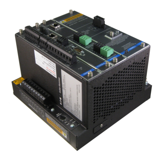
Page 150: Power Xpert Meter Option Cards
NOTE: Each terminal plate over- laps and fits together in specific order, requiring the correct disas- sembly and reassembly sequence. Power Xpert Meter Card Definitions PXMIO-B (Discrete Input/Output) PXMCE-B (Communication Expansion) PXMCM-1 (Communication Main) PXMPS-1 Power Supply Card IM02601004E Page 144 www.eaton.com... -
Page 151: Optional I/O Card
2) THIS DEVICE MUST ACCEPT ANY INTERFERENCE RECEIVED, INCLUDING INTERFERENCE THAT MAY CAUSE UNDESIRED OPERATION. S1 LED S1 LED Customer Satisfaction for technical support www.EatonElectrical.com Meter Test LED (Follows state of S1) <http://www.EatonElectrical.com 1-800-809-2772 or 1-414-449-7100 10VA Source MAX PXMIO-B PXCE-B PXCM-5 PXPS-1 IM02601004E www.eaton.com Page 145... -
Page 152: 1Ms Time Stamping Of Digital And Sub-Cycle Disturbance Events
NTP server IP address must be configured in the communications setup page. Eaton recommends the use of an NTP server to synch the Power Xpert Meter for 1 ms time stamping applications to minimize wiring and installation costs. -
Page 153: Satellite Time Reference (Cyber-Sciences Str-100)
STR 100 + G - 1 2 3 4 1 2 3 4 5 6 7 8 9 10 11 12 PXIO-B PXIO Phoenix Contact PLC-BSC-24DC/21 Internal 24Vdc Source Power Xpert Meter PX Meter IM02601004E www.eaton.com Page 147... -
Page 154: Communications Expansion Card (Pxmce Card)
Slave Gateway or a Modbus slave RTU. This port defaults as disabled. Note: The Power Xpert Meter must be equipped with a Communications Expansion card in order to interface to the NTP Time Server. IM02601004E Page 148 www.eaton.com... -
Page 155: Communication Ports (Pxmce Card)
• CE31 Data A (-) • CE32 Data B (+) • CE33 Shield (RS485 common) CE4 - COM3 - DTE DB9 RS232 interface is configurable as Modbus RTU Slave or Gate- way Master/Slave. Factory default setting is disabled. IM02601004E www.eaton.com Page 149... - Page 156 D Option Cards Com 2 Jumpers Master Slave Jumper Setting Jumper ID Slave Port Master Port Com 2 NOTE: Care should be taken to keep jumpers A and B set to the same value. IM02601004E Page 150 www.eaton.com...
-
Page 157: E Standard Cards
Individual terminals per block start with 1 and increase along the terminal block. The one exception is the V x auxillary terminal which increments on top of VT. IM02601004E www.eaton.com Page 151... -
Page 158: Power Xpert Meter Cards
NOTE: Each terminal plate over- laps and fits together in specific order, requiring correct disassembly and reassembly sequence. Power Xpert Meter Card Definitions PXMIO-B (Discrete Input/Output) PXCE-B (Communication Expansion) PXMCM-5 (Communication Main) PXPS-X Power Supply Card (PS-1,4...) IM02601004E Page 152 www.eaton.com... -
Page 159: Communication Main (Pxmcm) Card
CM6 - 24Vdc 10W max – Used to power the 6” Color Touch Screen Display if the cable distance is less than 30M. If greater than 30M, use a separate 24V supply to power the Display. • CM61 Shield • CM62 24V+ • CM63 24V common IM02601004E www.eaton.com Page 153... -
Page 160: Pxmcm Com 0 And Com 1 Rs485 Bias Resistors (Terminals Cm3, Cm5)
• The jumpers designators are stenciled as C0 A and C0 B; C1A and C1B. Positions N are for not engaged and positions Rb are for engaged. See illustration on the following page. • Com 0 has jumpers C0 A and C0 B • Com 1 has jumpers C1A and C1B IM02601004E Page 154 www.eaton.com... - Page 161 C1 B C0 A Com 0 C0 B C1 A C1 A C1 A C2 B Com 1 Com 1 Jumpers NOTE: Care should be taken to keep jumpers A and B set to the same value. IM02601004E www.eaton.com Page 155...
-
Page 162: Source Outputs Cm4 & Cm6
If during a voltage sag the input to the power supply is too low for normal operation, the CM4 and CM6 24V outputs are turned off to conserve ride through energy. This output drop will cause the display to cycle power and re-initialize after full voltage is restored. IM02601004E Page 156 www.eaton.com... -
Page 163: Power Supply Card Pxmps-1
ON or Factory Test Mode - The meter should never be operated in this mode. The meter will indicate that it’s in factory test mode through a repeating series of three flashes on the red Status LED. IM02601004E www.eaton.com Page 157... -
Page 164: Diagnostic Dip Switch Settings
E Standard Cards E.6. Diagnostic DIP Switch Settings Should a problem arise with your meter, EATON support personnel may ask you to enable a diag- nostic mode using the DIP switches. When in diagnostic mode, Eaton personnel may instruct you to connect a laptop to the meter and either retrieve files or perform other tasks on the meter. -
Page 165: F Data Files
A data file (with a .dat extension) All three files are required for data exchange. The COMTRADE files store the following data: Voltage Current Digital Input Channel* VAGAUX VBGAUX VCGAUX RESERVED1 *Waveforms (1 ms resolution) from digital inputs 1 through 8. IM02601004E www.eaton.com Page 159... -
Page 166: Energy Logs
Access, or other spreadsheet, graphing, and database applications. The log files contain the following data fields: • Date • Time • Forward kW Demand • Reverse kW Demand • Net kW Demand • Sum kW Demand IM02601004E Page 160 www.eaton.com... -
Page 167: Trend Logs
The log file format is a comma-separated values (CSV) file that can be readily loaded into Microsoft Excel or other spreadsheet, data analysis, or database applications. Because the meter logs so much data, the trend data is broken down into three separate files: • Trend_log_yyyymmdd.csv • Trend_HarmMag_yyyymmdd.csv IM02601004E www.eaton.com Page 161... - Page 168 FundamentalVcn(min) FundamentalVcn(max) InterHarmonicIa(avg) InterHarmonicIa(min) InterHarmonicIa(max) InterHarmonicIb(avg) InterHarmonicIb(min) InterHarmonicIb(max) InterHarmonicIc(avg) InterHarmonicIc(min) InterHarmonicIc(max) InterHarmonicIn(avg) InterHarmonicIn(min) InterHarmonicIn(max) InterHarmonicVab(avg) InterHarmonicVab(min) InterHarmonicVab(max) InterHarmonicVabxmr(avg) InterHarmonicVabxmr(min) InterHarmonicVabxmr(max) InterHarmonicVan(avg) InterHarmonicVan(min) InterHarmonicVan(max) InterHarmonicVbc(avg) InterHarmonicVbc(min) InterHarmonicVbc(max) InterHarmonicVbcxmr(avg) InterHarmonicVbcxmr(min) InterHarmonicVbcxmr(max) InterHarmonicVbn(avg) InterHarmonicVbn(min) InterHarmonicVbn(max) InterHarmonicVca(avg) InterHarmonicVca(min) InterHarmonicVca(max) InterHarmonicVcaxmr(avg) IM02601004E Page 162 www.eaton.com...
- Page 169 EvenHarmIbPct(min) EvenHarmIbPct(max) EvenHarmIcPct(avg) EvenHarmIcPct(min) EvenHarmIcPct(max) EvenHarmInPct(avg) EvenHarmInPct(min) EvenHarmInPct(max) EvenHarmVabPct(avg) EvenHarmVabPct(min) EvenHarmVabPct(max) EvenHarmVabxmrPct(avg) EvenHarmVabxmrPct(min) EvenHarmVabxmrPct(max) EvenHarmVanPct(avg) EvenHarmVanPct(min) EvenHarmVanPct(max) EvenHarmVbcPct(avg) EvenHarmVbcPct(min) EvenHarmVbcPct(max) EvenHarmVbcxmrPct(avg) EvenHarmVbcxmrPct(min) EvenHarmVbcxmrPct(max) EvenHarmVbnPct(avg) EvenHarmVbnPct(min) EvenHarmVbnPct(max) EvenHarmVcaPct(avg) EvenHarmVcaPct(min) EvenHarmVcaPct(max) EvenHarmVcaxmrPct(avg) EvenHarmVcaxmrPct(min) EvenHarmVcaxmrPct(max) EvenHarmVcnPct(avg) EvenHarmVcnPct(min) EvenHarmVcnPct(max) InterHarmIaPct(avg) IM02601004E www.eaton.com Page 163...
- Page 170 TotalHarmVabxmrPct(avg) TotalHarmVabxmrPct(min) TotalHarmVabxmrPct(max) TotalHarmVanPct(avg) TotalHarmVanPct(min) TotalHarmVanPct(max) TotalHarmVbcPct(avg) TotalHarmVbcPct(min) TotalHarmVbcPct(max) TotalHarmVbcxmrPct(avg) TotalHarmVbcxmrPct(min) TotalHarmVbcxmrPct(max) TotalHarmVbnPct(avg) TotalHarmVbnPct(min) TotalHarmVbnPct(max) TotalHarmVcaPct(avg) TotalHarmVcaPct(min) TotalHarmVcaPct(max) TotalHarmVcaxmrPct(avg) TotalHarmVcaxmrPct(min) TotalHarmVcaxmrPct(max) TotalHarmVcnPct(avg) TotalHarmVcnPct(min) TotalHarmVcnPct(max) Trend_log_yyyymmdd.csv Data Fields Date Time FlickerPerceptSys(avg) FlickerPerceptSys(min) FlickerPerceptSys(max) PltVab(avg) PltVab(min) PltVab(max) PltVan(avg) IM02601004E Page 164 www.eaton.com...
- Page 171 IFb(min) IFb(max) IFc(avg) IFc(min) IFc(max) IFsys(avg) IFsys(min) IFsys(max) Ig200(avg) Ig200(min) Ig200(max) In200(avg) In200(min) In200(max) KFa(avg) KFa(min) KFa(max) KFb(avg) KFb(min) KFb(max) KFc(avg) KFc(min) KFc(max) KFsys(avg) KFsys(min) KFsys(max) NegSeqI(avg) NegSeqI(min) NegSeqI(max) NegSeqV(avg) NegSeqV(min) NegSeqV(max) NegSeqVxmr(avg) NegSeqVxmr(min) NegSeqVxmr(max) Pa(avg) IM02601004E www.eaton.com Page 165...
- Page 172 Vllavgxmr200(min) Vllavgxmr200(max) Vlnavg200(avg) Vlnavg200(min) Vlnavg200(max) Vng200(avg) Vng200(min) Vng200(max) ZeroSeqI(avg) ZeroSeqI(min) ZeroSeqI(max) ZeroSeqV(avg) ZeroSeqV(min) ZeroSeqV(max) ZeroSeqVxmr(avg) ZeroSeqVxmr(min) ZeroSeqVxmr(max) ACCESSING THE TREND LOG FILES Trend log files are in the trend directory on the meter’s anonymous FTP site. IM02601004E Page 166 www.eaton.com...
-
Page 173: G Root Certificate Authority Installation
1. Open the browser and type the IP address of the meter followed by the path “/ca.html” in the address bar. For example: https://192.168.1.1/ca.html The install CA certificate page appears. Figure 1: Install CA Certificate Page. 2. Click the Root CA Certificate link. IM02601004E www.eaton.com Page 167... - Page 174 Figure 2: File Download Dialog Box. 4. In the Certificate dialog box, click the Install Certificate… button. NOTE The certificate cannot be verified yet because it is issued by a non-trusted CA. Figure 3: Certification Path Window. IM02601004E Page 168 www.eaton.com...
- Page 175 Click Next. Figure 4: Certificate Import Wizard. 6. The certificate wizard confirms the selected setting for certificate import. Click Finish. Figure 5: Certificate Import Wizard – Confirming Import Settings. IM02601004E www.eaton.com Page 169...
-
Page 176: Installing Root Ca With Google Chrome
7. A new dialog box window opens to verify that the import was done successfully (see Figure 6). 8. Click OK. 9. Click OK to close the Certificate Window. The installation process is complete. You can now access the meter using the https protocol (For example: https://192.168.1.1/). IM02601004E Page 170 www.eaton.com... -
Page 177: Installing Root Ca With Mozilla Firefox
3. Click the Trust this CA to identify web sites check box option. Figure 8: Downloading Certificate Window. 4. Click OK to complete the installation process. The installation process is complete. You can now access the meter using the https protocol (for example, https://192.168.1.1/ ca.html). IM02601004E www.eaton.com Page 171... -
Page 178: Installing Root Ca With Edge
(For example: https://192.168.1.1/ca.html). The install CA certificate page appears. Figure 9: Install CA Certificate Page. 2. Click the Root CA Certificate link. 3. Click the Open button. Figure 10: File Download Dialog Box. IM02601004E Page 172 www.eaton.com... - Page 179 NOTE The certificate cannot be verified yet because it is issued by a non-trusted CA. Figure 11: Certification Path Window. 5. The Certificate Import Wizard window opens. Verify that the default setting, Current User, is selected and then Click Next. Figure 12: Certification Import Wizard – Welcome Screen IM02601004E www.eaton.com Page 173...
- Page 180 Click Next. Figure 13: Certification Import Wizard – Certificate Store 7. The certificate wizard confirms the selected setting for certificate import. Click Finish. Figure 14: Certification Import Wizard – Confirming Import Settings IM02601004E Page 174 www.eaton.com...
- Page 181 G Root Certificate Authority Installation 8. A new dialog box window opens to verify that the import was done successfully. Figure 15: Import Successful Dialog Box. 9. Click OK. IM02601004E www.eaton.com Page 175...
- Page 182 G Root Certificate Authority Installation IM02601004E Page 176 www.eaton.com...
-
Page 183: H Specifications
Pollution Degree II for Meter and Display Back Pollution Degree III for Display Front Panel Housing must be => NEMA 12 or IP52 Panel must be flat to accept Display gasket Display Ethernet cover must be closed IM02601004E www.eaton.com Page 177... - Page 184 ~ 2.2K ohm Input current draw ~ 10 mA Minimum pulse width 10 millisecond Maximum pulse rate 20 Hz Common TVS clamped to ground ~ 300V Wiring to 9 position removable terminal plug 12-18 AWG, wire ferrules recommended IM02601004E Page 178 www.eaton.com...
- Page 185 600 V all CT circuits to ground Installation Category CAT III Dielectric Withstand All inputs to ground 3500 Vac / 1 min ADC Conversion 30.72 ksps through delta-sigma A/D True rms processing at 512 sample/cycle Delta sigma A/D oversampling rate: 4096 samples/cycle IM02601004E www.eaton.com Page 179...
- Page 186 (Temporary transitions- Surge/transients) +/- 1-8000 Vpk L:G Abuse Overload Rating 1000 Vrms Sustained Input Impedance - 2 mega ohm Accuracy +/-1V Wiring to removable terminal plug Range 10 AWG - 18 AWG ADC Conversion 1 or 6 MHz IM02601004E Page 180 www.eaton.com...
- Page 187 Shield CM 4.2* 24 V+ Source CM 4.3* Common COM 0 CM 5.1 Data A CM 5.2 Data B CM 5.3 Shield / Common CM 6.1* Shield CM 6.2* 24 V+ Source CM 6.3* Comonm COMMUNI IM02601004E www.eaton.com Page 181...
- Page 188 Min. isolation voltage: 1,000 Vac 1 min. Wire Type Equal or exceed 5 UTP Category 5 unshielded twisted pair recommended cable. Max. length: 100 meters Use of STP cable will yield improved EMI performance Connector Type Male RJ45 modular, Grounded Metal Shield IM02601004E Page 182 www.eaton.com...
- Page 189 Com 0, Com 1, Com 2 ** Specifications Description Baud Rates 9600 - 115.2K Duplex Half Supported Protocols Modbus gateway to other meters or a Modbus slave on a sub-network. *Field circuit common is clamped to ground with TVS diode. IM02601004E www.eaton.com Page 183...
- Page 190 Optical isolation from all other inputs *and outputs, 240 Vac / 1 min. Cable Type Shielded Twisted Pair, 22 AWG Max. Cable Length 50 feet, DTE 9 pin dsub *Field circuit common is clamped to ground with TVS diode at 300V. IM02601004E Page 184 www.eaton.com...
- Page 191 H Specifications IM02601004E www.eaton.com Page 185...
- Page 192 1000 Eaton Boulevard Cleveland Ohio 44122 United- States Tel. 1--800-525-2000 www. Eaton.com © 2017 Eaton All Rights Reserved Eaton is a registered trademark. Printed in USA Publication No. IM02601004E TBG1351 All other trademarks are property of their August 2017 respective owners.
Need help?
Do you have a question about the Power Xpert PXM 4000 and is the answer not in the manual?
Questions and answers