Transition Networks SISPM1040-3248-L User Manual
Rack mount industrial ethernet switch
Hide thumbs
Also See for SISPM1040-3248-L:
- Cli reference manual (250 pages) ,
- Quick start manuals (2 pages) ,
- Install manual (50 pages)
Table of Contents
Advertisement
Quick Links
Transition Networks
SISPM1040‐3248‐L Web User Guide
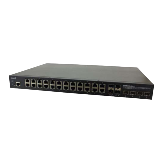
SISPM1040‐3248‐L
Rack Mount Industrial Ethernet Switch
Managed Hardened PoE+ Switch, (24) 10/100/1000Base‐T PoE+ ports +
(4) 100/1000Base‐X SFP/RJ‐45 Combo + (4) 1G/10G SFP+
Web User Guide
33763 Rev. A
33763 Rev. A
https://www.transition.com
Page 1 of 413
Advertisement
Table of Contents

Related Manuals for Transition Networks SISPM1040-3248-L


Summary of Contents for Transition Networks SISPM1040-3248-L
- Page 1 Transition Networks SISPM1040‐3248‐L Web User Guide SISPM1040‐3248‐L Rack Mount Industrial Ethernet Switch Managed Hardened PoE+ Switch, (24) 10/100/1000Base‐T PoE+ ports + (4) 100/1000Base‐X SFP/RJ‐45 Combo + (4) 1G/10G SFP+ Web User Guide 33763 Rev. A 33763 Rev.
-
Page 2: Safety Warnings And Cautions
Transition Networks SISPM1040‐3248‐L Web User Guide Safety Warnings and Cautions These products are not intended for use in life support products where failure of a product could reasonably be expected to result in death or personal injury. Anyone using this product in such an application without express written consent of an officer of Transition Networks does so at their own risk, and agrees to fully indemnify Transition Networks for any damages that may result from such use or sale. Attention: this product, like all electronic products, uses semiconductors that can be damaged by ESD (electrostatic discharge). Always observe appropriate precautions when handling. NOTE: Emphasizes important information or calls your attention to related features or instructions. WARNING: Alerts you to a potential hazard that could cause personal injury. CAUTION: Alerts you to a potential hazard that could cause loss of data, or damage the system or equipment. SISPM1040‐3248‐L Web User Guide, 33763 Rev. A Record of Revisions Rev Date Description of Changes A 10/18/18 Initial release at FW v8.40.428 Trademark notice: All trademarks and registered trademarks are the property of their respective owners. All other products or service names used in this publication are for identification purposes only, and may be trademarks or registered trademarks of their respective companies. All other trademarks or registered trademarks mentioned herein are the property of their respective holders. Copyright restrictions: © 2018 Transition Networks, Inc. All rights reserved. No part of this work may be reproduced or used ... -
Page 3: Table Of Contents
Transition Networks SISPM1040‐3248‐L Web User Guide Contents Safety Warnings and Cautions .......................... 2 Chapter 1 ‐ Introduction ............................ 9 1‐1 Key Features ............................... 9 1‐2 About This Manual ............................. 9 1‐3 Related Manuals .............................. 9 Chapter 2 – Web User Interface ........................ 10 2‐1 Initial Configuration ............................10 Chapter 3 ‐ System Configuration ........................ 11 3‐1 System Information ............................11 3‐2 IP Address ................................13 3‐2.1 Settings ..............................13 3‐2.2 Advanced Settings .............................15 3‐2.3 Status ................................19 ... - Page 4 Transition Networks SISPM1040‐3248‐L Web User Guide 4‐5.1 Static Configuration ..........................85 4‐5.2 LACP Configuration ...........................87 4‐5.3 System Status ............................89 4‐5.4 Internal Status ............................90 4‐5.5 Neighbor Status ............................92 4‐5.6 Port Status ..............................94 4‐6 Loop Protection ..............................95 4‐6.1 Configuration ............................95 4‐6.2 Status ................................97 4‐7 UDLD ................................98 4‐7.1 UDLD Configuration ..........................98 4‐7.2 UDLD Status ............................ 100 Chapter 5 ‐ PoE Management ........................ 102 5‐1 PoE Configuration ............................ 102 5‐2 PoE Management > PoE Status ........................ 105 5‐3 PoE Management > PoE Power Delay ...................... 107 5‐4 PoE Management > PoE Auto Checking.................... 108 5‐5 PoE Management > PoE Scheduling Profile .................... 110 Chapter 6 – VLAN Management ...
- Page 5 Transition Networks SISPM1040‐3248‐L Web User Guide 7‐7 DSCP ................................ 145 7‐7.1 Port DSCP ............................... 145 7‐7.2 DSCP Translation ............................ 147 7‐7.3 DSCP Classification .......................... 149 7‐7.4 DSCP‐Based QoS ............................ 150 7‐8 QoS Control List ............................ 151 7‐8.1 Configuration ............................ 151 7‐8.2 Status .............................. 155 7‐9 Qos Statistics .............................. 157 7‐10 WRED ................................ 158 Chapter 8 – Spanning Tree .......................... 160 8‐1 STP Configuration ............................ 160 8‐2 MSTI Configuration ............................ 163 8‐3 STP Status .............................. 169 8‐4 Port Statistics .............................. 173 Chapter 9 – MAC Address Tables ........................ 174 9‐1 Configuration .............................. 174 9‐2 Information .............................. 176 Chapter 10 – Multicast .......................... 178 ...
- Page 6 Transition Networks SISPM1040‐3248‐L Web User Guide 11‐1.2 Snooping Table............................. 215 11‐1.3 Detailed Statistics .......................... 216 11‐2 Relay ................................ 218 11‐2.1 Configuration ............................ 218 11‐2.2 Statistics ............................... 220 11‐3 Server ................................ 222 11‐3.1 Configuration ............................ 222 11‐3.2 Status .............................. 224 Chapter 12 – Security ............................. 225 12‐1 Management ............................... 225 12‐1.1 Account .............................. 225 12‐1.2 Privilege Levels ............................. 227 12‐1.3 Auth Method ............................ 229 12‐1.4 Access Method ............................. 231 12‐1.5 HTTPS .............................. 233 12‐2 802.1X ................................. 235 12‐2.1 Configuration ............................ 235 ...
- Page 7 Transition Networks SISPM1040‐3248‐L Web User Guide 14‐2.1 Communities ............................ 291 14‐2.2 Users ................................ 292 14‐2.3 Groups .............................. 294 14‐2.4 Views .............................. 296 14‐2.5 Access .............................. 298 14‐3 RMON Statistics ............................ 300 14‐3.1 Configuration ............................ 300 14‐3.2 Status .............................. 301 14‐4 RMON History ............................. 303 14‐4.1 Configuration ............................ 303 14‐4.2 Status .............................. 304 14‐5 RMON Alarm ............................... 306 14‐5.1 Configuration ............................ 306 14‐5.2 Status .............................. 308 14‐6 RMON Event .............................. 310 14‐6.1 Configuration ............................ 310 14‐6.2 Status .............................. 311 Chapter 15 – MEP ............................ 313 15‐1 MEP Configuration ...
- Page 8 Transition Networks SISPM1040‐3248‐L Web User Guide Chapter 19 – Diagnostics .......................... 361 19‐1 Ping ................................ 361 19‐2 Traceroute .............................. 363 19‐3 Cable Diagnostics ............................ 365 19‐4 Mirroring .............................. 367 19‐5 sFlow ................................ 369 19‐5.1 Configuration ............................ 369 19‐5.2 Statistics ............................... 372 Chapter 20 – Maintenance .......................... 374 20‐1 Configuration .............................. 374 20‐1.1 Save startup‐config .......................... 374 20‐1.2 Backup .............................. 375 20‐1.3 Restore .............................. 376 201.4 Activate .............................. 377 20‐1.5 Delete .............................. 377 20‐2 Restart Device ............................. 379 20‐3 Factory Defaults ............................ 380 ...
-
Page 9: Chapter 1 - Introduction
Transition Networks SISPM1040‐3248‐L Web User Guide Chapter 1 ‐ Introduction The SISPM1040‐3248‐L switch is a next‐generation rack mount industrial grade Ethernet switches offering powerful L2 and basic L3 features with advanced functionality and usability. In addition to the extensive management features, the SISPM1040‐3248‐L also provides Carrier Ethernet features such as OAM, CFM, ERPS, EPS, and PTPv2 which make them suitable for industrial and Carrier Ethernet applications. The SISPM1040‐3248‐L delivers 16/24 (10M/100M/1G) RJ45/PoE+ (support 802.3at/af, and total up to 250W/370W) ports, 4 GbE SFP ports, 2/4 GbE/10G SFP+ ports and RJ45 Console port. The SISPM1040‐3248‐L provides high hardware performance and environment flexibility for industrial applications. 1-1 Key Features DMS (Device Management System) built in Carrier Ethernet features for easier manageability, security, and QoS IEEE 1588v2 PTP IEEE 802.3ah OAM IEEE 802.1ag CFM (ITU‐T Y.1731 Performance monitoring) ITU‐T Y.1564 (RFC2544) Ethernet Service Activation Test ITU‐T G.8031 Ethernet Linear Protection Switching (EPS) ITU‐T G.8032 Ethernet Ring Protection Switching (ERPS) ... -
Page 10: Chapter 2 - Web User Interface
Transition Networks SISPM1040‐3248‐L Web User Guide Chapter 2 – Web User Interface 2-1 Initial Configuration This chapter describes how to configure and manage the SISPM1040‐3248‐L via the web user interface (UI). The web UI lets you configure and monitor switch operating parameters via any switch port. The default values are listed below: IP Address 192.168.1.77 Subnet Mask 255.255.255.0 Default Gateway 192.168.1.254 ... -
Page 11: Chapter 3 - System Configuration
Transition Networks SISPM1040‐3248‐L Web User Guide Chapter 3 ‐ System Configuration This chapter describes System Information page parameters. 3-1 System Information You can identify the system by configuring a system name, location and a contact of the switch. Figure 2-1: System Information Parameter descriptions: Model Name : Displays the factory defined model name for identification purposes (e.g., SISPM1040‐3248‐L). System Description : Displays the system description (e.g., Managed Hardened PoE+ Switch, (24) 10/100/1000Base‐T PoE+ ports + (4) 100/1000Base‐X SFP/RJ‐45 Combo + (4) 1G/10G SFP+). Location : The system location configured at Configuration > System > Information > System Location. Contact : The system contact configured at Configuration > System > Information > System Contact. System Name : Displays the user‐defined system name that were configured in System > System Information > Configuration > System Name. System Date : The current (GMT) system time and date. The system time is obtained through the Timing server running on the switch, if any. System Uptime : The period of time the device has been operational. Bootloader Version : Displays the current boot loader version number (e.g., v1_2‐00c98fd). Firmware Version : The software version and date of the firmware on this switch (e.g., v8.40.428 2018‐09‐19). 33763 Rev. A https://www.transition.com Page 11 of 413... - Page 12 Transition Networks SISPM1040‐3248‐L Web User Guide Hardware Version : Displays the hardware version of the device. Mechanical Version : Displays the mechanical version of the device. Serial Number : The serial number of this switch. MAC Address : The MAC Address of this switch. Powers Status : Displays the powers status of the system(e.g., Normal). Powers : Displays the power sources of the system (e.g., PWR_1.0V:1.01V; PWR_3.3V:3.24V; PWR_2.5V:2.60V; PWR_1.8V:11.87V). Temperature Status : Displays the temperature status of the system. (e.g., Normal) Temperature 1 : Displays the temperature 1 of the system (e.g., 36(C) ; 96(F)). Temperature 2 : Displays the temperature 2 of the system (e.g., 39(C) ; 102(F)). CPU Load (100ms, 1s, 10s) : Displays the cpu loading(100ms, 1s, 10s) of the system (e.g., 0%, 7%, 5%). Buttons Apply : Click to save changes. Reset : Click to undo any changes made locally and revert to previously saved values. Refresh : Click to refresh the page immediately. Auto‐refresh : Click to refresh the page automatically every 3 seconds. 33763 Rev. A https://www.transition.com Page 12 of 413...
-
Page 13: Ip Address
Transition Networks SISPM1040‐3248‐L Web User Guide 3-2 IP Address 3‐2.1 Settings The IPv4 address for the switch can be obtained via DHCP Server for VLAN 1. To manually configure an address, you must change the switch's default settings to values that are compatible with your network. You may also need to establish a default gateway between the switch and management stations that exist on another network segment. This page lets you configure the IP basic settings, control IP interfaces and IP routes. Web Interface To configure an IP Settings in the web interface: 1. Click System, IP Address, and Settings. 2. Enable or disable the IPv4 DHCP Client. 3. Specify the IPv4 Address, Subnet Mask, Gateway. 4. Select DNS Server. 5. Click Apply Figure 3‐2.1: IP Settings page Parameter descriptions: IPv4 DHCP Client Enable : Enable the DHCP client by checking this box. If this option is enabled, the system will configure the IPv4 address and mask of the interface using the DHCP protocol. The DHCP client will announce the configured System Name as hostname to provide DNS lookup. ... - Page 14 Transition Networks SISPM1040‐3248‐L Web User Guide Gateway : The IP address of the IP gateway. Valid format is dotted decimal notation or a valid IPv6 notation. Gateway and Network must be of the same type. DNS Server : This setting controls the DNS name resolution done by the switch. There are four servers available for configuration, and the index of the server presents the preference (less index has higher priority) in doing DNS name resolution. These modes are supported: No DNS server : No DNS server will be used. Configured IPv4 : Explicitly provide the valid IPv4 unicast address of the DNS Server in dotted decimal notation. Make sure the configured DNS server could be reachable (e.g. via PING) for activating DNS service. Configured IPv6 : Explicitly provide the valid IPv6 unicast (except linklocal) address of the DNS Server. Make sure the configured DNS server could be reachable (e.g. via PING6) for activating DNS service. From any DHCPv4 interfaces : The first DNS server offered from a DHCPv4 lease to a DHCPv4‐enabled interface will be used. From this DHCPv4 interface : Specify from which DHCPv4‐enabled interface a provided DNS server should be preferred. From any DHCPv6 interfaces : The first DNS server offered from a DHCPv6 lease to a DHCPv6‐enabled interface will be used. From this DHCPv6 interface : Specify from which DHCPv6‐enabled interface a provided DNS server should be preferred. Buttons Apply : Click to save changes. ...
-
Page 15: 3-2.2 Advanced Settings
Transition Networks SISPM1040‐3248‐L Web User Guide 3‐2.2 Advanced Settings Configure the switch‐managed IP information on this page, including IP basic settings, control IP interfaces and IP routes. The maximum number of interfaces supported is 128 and the maximum number of routes is 128. Web Interface To configure an Advanced Settings in the web interface: Click System, IP Address and Advanced Settings. Click Add Interface then you can create new Interface on the switch. Click Add Route then you can create new Route on the switch. Click Apply. Figure 3‐2.2: Advanced IP settings 33763 Rev. A https://www.transition.com Page 15 of 413... - Page 16 Transition Networks SISPM1040‐3248‐L Web User Guide Parameter descriptions: Advanced Settings Mode : Configure whether the IP stack should act as a Host or a Router. In Host mode, IP traffic between interfaces will not be routed. In Router mode traffic is routed between all interfaces. DNS Server : This setting controls the DNS name resolution done by the switch. There are four servers available for configuration, and the index of the server presents the preference (less index has higher priority) in doing DNS name resolution. These modes are supported: No DNS server : No DNS server will be used. Configured IPv4 : Explicitly provide the valid IPv4 unicast address of the DNS Server in dotted decimal notation. Make sure the configured DNS server could be reachable (e.g. via PING) for activating DNS service. Configured IPv6 : Explicitly provide the valid IPv6 unicast (except linklocal) address of the DNS Server. Make sure the configured DNS server could be reachable (e.g. via PING6) for activating DNS service. From any DHCPv4 interfaces : The first DNS server offered from a DHCPv4 lease to a DHCPv4‐enabled interface will be used. From this DHCPv4 interface : Specify from which DHCPv4‐enabled interface a provided DNS server should be preferred. From any DHCPv6 interfaces : The first DNS server offered from a DHCPv6 lease to a DHCPv6‐enabled interface will be used. From this DHCPv6 interface : Specify from which DHCPv6‐enabled interface a provided DNS server should be preferred. DNS Proxy : : When DNS proxy is enabled, system will relay DNS requests to the currently configured DNS server, and reply as a DNS resolver to the client devices on the network. Only IPv4 DNS proxy is now supported. IP Interfaces DHCP Per Port Mode : Enable or Disable DHCP per port. The default is Disabled. The DHCP Per Port IP range must be equal to switch twisted‐pair port number (24). ...
- Page 17 Transition Networks SISPM1040‐3248‐L Web User Guide IPv4 DHCP Fallback Timeout : The number of seconds for trying to obtain a DHCP lease. After this period expires, a configured IPv4 address will be used as IPv4 interface address. A value of zero disables the fallback mechanism, such that DHCP will keep retrying until a valid lease is obtained. Legal values are 0 to 4294967295 seconds. IPv4 DHCP Current Lease : For DHCP interfaces with an active lease, this column show the current interface address, as provided by the DHCP server. IPv4 Address : The IPv4 address of the interface in dotted decimal notation. If DHCP is enabled, this field is not used. The field may also be left blank if IPv4 operation on the interface is not desired. The Subnet of VLANs cannot overlap. IPv4 Mask Length : The IPv4 network mask, in number of bits (prefix length). Valid values are between 0 and 30 bits for an IPv4 address. If DHCP is enabled, this field is not used. The field may also be left blank if IPv4 operation on the interface is not desired. DHCPv6 Enable : Enable the DHCPv6 client by checking this box. If this option is enabled, the system will configure the IPv6 address of the interface using the DHCPv6 protocol. DHCPv6 Rapid Commit : Enable the DHCPv6 Rapid‐Commit option by checking this box. If this option is enabled, the DHCPv6 client terminates the waiting process as soon as a Reply message with a Rapid Commit option is received. This option is only manageable when DHCPv6 client is enabled. DHCPv6 Current Lease : For DHCPv6 interface with an active lease, this column shows the interface address provided by the DHCPv6 server. IPv6 Address : The IPv6 address of the interface. An IPv6 address is in 128‐bit records represented as eight fields of up to four hexadecimal digits with a colon separating each field (:). For example, fe80::215:c5ff:fe03:4dc7. The symbol :: is a special syntax that can be used as a shorthand way of representing multiple 16‐bit groups of contiguous zeros; but it can appear only once. It can also represent a legally valid IPv4 address. For example, ::192.1.2.34. This field may be left blank if IPv6 operation on the interface is not desired. IPv6 Mask Length : The IPv6 network mask, in number of bits (prefix length). Valid values are between 1 and 128 ...
- Page 18 Transition Networks SISPM1040‐3248‐L Web User Guide Mask Length : The destination IP network or host mask, in number of bits (prefix length). It defines how much of a network address that must match, in order to qualify for this route. Valid values are between 0 and 32 bits respectively 128 for IPv6 routes. Only a default route will have a mask length of 0 (as it will match anything). Gateway : The IP address of the IP gateway. Valid format is dotted decimal notation or a valid IPv6 notation. Gateway and Network must be of the same type. Distance (Only for IPv4) : The distance value of route entry is used to provide the priority information of the routing protocols to routers. When there are two or more different routing protocols are involved and have the same destination, the distance value can be used to select the best path. Next Hop VLAN (Only for IPv6) : The VLAN ID (VID) of the specific IPv6 interface associated with the gateway. The given VID ranges from 1 to 4095 and will be effective only when the corresponding IPv6 interface is valid. If the IPv6 gateway address is link‐local, it must specify the next hop VLAN for the gateway. If the IPv6 gateway address is not link‐local, system ignores the next hop VLAN for the gateway. Buttons Add Interface : Click to add a new IP interface. A maximum of 128 interfaces is supported. Add Route : Click to add a new IP route. A maximum of 128 routes is supported. Apply : Click to save changes. The message “Update success!” displays when successful. Reset : Click to undo any changes made locally and revert to previously saved values. Messages Message: DHCP Per Port IP range (192.168.1.78 ‐ 192.168.1.98) is not equal to switch TP port number (24) Recovery : Click OK to clear the message and re‐enter the DHCP Per Port IP parameter above. Message: Update Success! Meaning: Click OK to clear the message and continue operation. 33763 Rev.
-
Page 19: 3-2.3 Status
Transition Networks SISPM1040‐3248‐L Web User Guide 3‐2.3 Status 3‐2.3.1 IP Status This page displays the status of the IP protocol layer. The status is defined by the IP interfaces, the IP routes and the neighbor cache (ARP cache) status. Web Interface To display the log configuration in the web interface: 1. Click System, IP Address, Status, and IP Status. 2. View the IP status information. Figure 3‐2.3.1: IP Status Parameter descriptions: IP Interfaces Interface : Shows the name of the interface. Type : Shows the address type of the entry. This may be LINK or IPv4. Address : Shows the current address of the interface (of the given type). Status : Shows the status flags of the interface (and/or address). IP Routes Network : Shows the destination IP network or host address of this route. 33763 Rev. - Page 20 Transition Networks SISPM1040‐3248‐L Web User Guide Gateway : Shows the gateway address of this route. Status : Shows the status flags of the route. Neighbor cache IP Address : Shows the IP address of the entry. Link Address : Shows the Link (MAC) address for which a binding to the IP address given exist. Buttons Auto‐refresh : Click to refresh the page automatically every 3 seconds. Refresh : Click to refresh the page immediately. 33763 Rev. A https://www.transition.com Page 20 of 413...
- Page 21 Transition Networks SISPM1040‐3248‐L Web User Guide 3‐2.3.2 Routing Information Base IP Routing includes a set of protocols that determine the path data follows across multiple networks from its source to its destination. Data is routed from its source to its destination via a series of routers, and across multiple networks. A routing protocol specifies how routers communicate with each other, distributing information that enables them to select routes between any two nodes on a computer network. Routing algorithms determine the specific route of choice. Each router has prior knowledge only of directly attached networks. A routing protocol shares this information first among immediate neighbors, then throughout the network, allowing the routers to determine the network. The specific characteristics of routing protocols include the manner in which they avoid routing loops, the manner in which they select preferred routes, using information about hop costs, the time they require to reach routing convergence, their scalability, and other factors. Each page shows up to 999 table entries, selected through the "entries per page" input field. When first visited, the web page will show the beginning entries of this table. The "Start from ID" input field lets you change the starting point in this table. Clicking the Refresh button will update the displayed table starting from that or the closest next entry match. In addition, these input fields will upon a Refresh button click, assume the value of the first displayed entry, allowing for continuous refresh with the same starting input field. Web Interface To display the log configuration in the web interface: 1. Click System, IP Address, Status, and Routing Info Base. 2. View the Routing Information Base data. Figure 3‐2.3.2: Routing Information Base Parameter descriptions: Start from Network / : Input field lets you change the starting point in this table. ...
- Page 22 Transition Networks SISPM1040‐3248‐L Web User Guide Protocol : Dropdown to select the protocol of the route. D (DHCP): The route is created by DHCP. C (Connected) : The destination network is connected directly. S (Static) : The route is created by user. 3‐6 OSPF O (OSPF) : The route is created by OSPF. See also section on page 49. Protocol : a table entry to display the route protocol. Codes: C ‐ connected, S ‐ static, O ‐ OSPF, * ‐ selected route, D ‐ DHCP installed route. Network/Prefix : Network and prefix (example 10.0.0.0/16) of the given route entry. NextHop : The IP address of next hop. The value '0.0.0.0' indicates the link is directly connected. Distance : The distance of the route. Metric : The metric of the route. Interface : The interface where the IP packet is outgoing. Uptime (hh:mm:ss) : The time until the route is created. State : Indicates if the destination network is reachable (Active) or not reachable (Inactive). Buttons Auto‐refresh : Click to refresh the page automatically every 3 seconds. Refresh : Click to manually refresh the page immediately. First page : Updates the table entries, starting from the first available entry. If the first entry of the table is displayed, the button is disabled. Previous page : Updates the table entries, ending at the entry prior to the first entry currently displayed. If the first entry of the table is displayed, the button is disabled. ...
-
Page 23: System Time
Transition Networks SISPM1040‐3248‐L Web User Guide 3-3 System Time The switch provides manual and automatic ways to set the system time via NTP. Manual setting is simple; you just input “Year”, “Month”, “Day”, “Hour” and “Minute” within the valid value range indicated in each item. Web Interface To configure Time in the web interface: 1. Click System and System Time 2. Specify the Time parameters. 3. Click Apply. Figure 2‐3: Time Configuration 33763 Rev. A https://www.transition.com Page 23 of 413... - Page 24 Transition Networks SISPM1040‐3248‐L Web User Guide Parameter descriptions: Time Configuration Clock Source : There are two modes for configuring how the Clock Source from. Select "Local Settings" : Clock Source from Local Time. Select "NTP Server" : Clock Source from NTP Server. System Date : Show the current time of the system. The year of system date limits between 2011 and 2037. Time Zone Configuration Time Zone : Lists various Time Zones worldwide. Select appropriate Time Zone from the drop down and click Apply to set. Acronym : User can set the acronym of the time zone. This is a user‐configurable acronym to identify the time zone. (Range: Up to 16 characters.) Daylight Saving Time Configuration Daylight Saving Time : This is used to set the clock forward or backward according to the configurations set below for a defined Daylight Saving Time duration. Select 'Disable' to disable the Daylight Saving Time configuration. Select 'Recurring' and configure the Daylight Saving Time duration to repeat the configuration every year. Select 'Non‐Recurring' and configure the Daylight Saving Time duration for single time configuration. (Default: Disabled). Start time settings : Week ‐ Select the starting week number. Day ‐ Select the starting day. Month ‐ Select the starting month. Hours ‐ Select the starting hour. Minutes ‐ Select the starting minute. End time settings : Week ‐ Select the ending week number. Day ‐ Select the ending day. ...
- Page 25 Transition Networks SISPM1040‐3248‐L Web User Guide Configure NTP Server : Click to configure NTP server, when ‘Use NTP Server’ is selected at Clock Source select dropdown (see above). NTP (Network Time Protocol) is used to sync the network time based Greenwich Mean Time (GMT). If you use NTP mode and select a built‐in NTP time server or manually specify a user‐defined NTP server as well as Time Zone, the switch will sync the time in a short after pressing <Apply> button. Though it synchronizes the time automatically, NTP does not update the time periodically without user’s processing. Time Zone is an offset time of GMT. You have to select the time zone first and then perform time sync via NTP because the switch will combine this time zone offset and updated NTP time to come out the local time, otherwise, you will not able to get the correct time. The switch supports configurable time zone from –12 to +13 step 1 hour. Default Time zone: +8 Hrs. Parameter descriptions : NTP Time‐Sync Interval : The switch is periodically transmitting NTP frames to its servers for having the network time information up‐to‐date. The interval between each NTP frame is determined by the NTP Time‐Sync Interval value. Valid values are 5, 10,15,30,60, and 120 minutes. Server 1 to 5 : Provide the NTP IPv4 or IPv6 address of this switch. IPv6 address is in 128‐bit records represented as eight fields of up to four hexadecimal digits with a colon separating each field (:). For example, 'fe80::215:c5ff:fe03:4dc7'. The symbol '::' is a special syntax that can be used as a shorthand way of representing multiple 16‐bit groups of contiguous zeros; but it can only appear once. It can also represent a legally valid IPv4 address. For example, '::192.1.2.34'. Buttons These buttons are displayed on the SNTP page: Apply :Click to save changes. Reset : Click to undo any changes made locally and revert to previously saved values. 33763 Rev. A https://www.transition.com Page 25 of 413...
-
Page 26: Lldp
Transition Networks SISPM1040‐3248‐L Web User Guide 3-4 LLDP The switch supports the LLDP. For current information on your switch model, The Link Layer Discovery Protocol (LLDP) provides a standards‐based method for enabling switches to advertise themselves to adjacent devices and to learn about adjacent LLDP devices. The Link Layer Discovery Protocol (LLDP) is a vendor‐neutral Link Layer protocol in the Internet Protocol Suite used by network devices for advertising their identity, capabilities, and neighbors on a IEEE 802 local area network, principally wired Ethernet. The protocol is formally referred to by the IEEE as Station and Media Access Control Connectivity Discovery specified in standards document IEEE 802.1AB. 3‐4.1 LLDP Configuration You can configure LLDP per port and set the detail parameters here; the settings will take effect immediately. This pagelets you view and configure current LLDP port settings. Web Interface To configure LLDP: 1. Click System, LLDP and LLDP configuration. 2. Modify LLDP timing parameters. 3. Set the required mode for transmitting or receiving LLDP messages. 4. Specify the information to include in the TLV field of advertised messages. 5. Click Apply. Figure 3‐4.1: LLDP Configuration 33763 Rev. - Page 27 Transition Networks SISPM1040‐3248‐L Web User Guide Parameter descriptions: LLDP Parameters Tx Interval :The switch periodically transmits LLDP frames to its neighbors for having the network discovery information up‐to‐date. The interval between each LLDP frame is determined by the Tx Interval value. Valid values are 5 ‐ 32768 seconds. Tx Hold : Each LLDP frame contains information about how long the information in the LLDP frame shall be considered valid. The LLDP information valid period is set to Tx Hold multiplied by Tx Interval seconds. Valid values are restricted to 2 ‐ 10 times. Tx Delay : If some configuration is changed (e.g. the IP address) a new LLDP frame is transmitted, but the time between the LLDP frames will always be at least the value of Tx Delay seconds. Tx Delay cannot be larger than 1/4 of the Tx Interval value. Valid values are restricted to 1 ‐ 8192 seconds. Tx Reinit : When a port is disabled, LLDP is disabled or the switch is rebooted, an LLDP shutdown frame is transmitted to the neighboring units, signaling that the LLDP information isn't valid anymore. Tx Reinit controls the amount of seconds between the shutdown frame and a new LLDP initialization. Valid values are restricted to 1 ‐ 10 seconds. LLDP Port Configuration Port : The switch port number of the logical LLDP port. Mode : Select LLDP mode. Rx only : The switch will not send out LLDP information, but LLDP information from neighbor units is analyzed. Tx only : The switch will drop LLDP information received from neighbors, but will send out LLDP information. Disabled : The switch will not send out LLDP information, and will drop LLDP information received from ...
- Page 28 Transition Networks SISPM1040‐3248‐L Web User Guide Both the CDP and LLDP support "system capabilities", but the CDP capabilities cover capabilities that are not part of the LLDP. These capabilities are shown as "others" in the LLDP neighbors’ table. If all ports have CDP awareness disabled the switch forwards CDP frames received from neighbor devices. If at least one port has CDP awareness enabled all CDP frames are terminated by the switch. Note: When CDP awareness on a port is disabled the CDP information isn't removed immediately, but gets removed when the hold time is exceeded. Trap : LLDP trapping notifies events such as newly‐detected neighboring devices and link malfunctions. Port Descr : Optional TLV: When checked the "port description" is included in LLDP information transmitted. Sys Name : Optional TLV: When checked the "system name" is included in LLDP information transmitted. Sys Descr : Optional TLV: When checked the "system description" is included in LLDP information transmitted. Sys Capa : Optional TLV: When checked the "system capability" is included in LLDP information transmitted. Mgmt Addr : Optional TLV: When checked the "management address" is included in LLDP information transmitted. Buttons Apply : Click to save changes. Reset : Click to undo any changes made locally and revert to previously saved values. 33763 Rev.
-
Page 29: 3-4.2 Lldp-Med Configuration
Transition Networks SISPM1040‐3248‐L Web User Guide 3‐4.2 LLDP‐MED Configuration Media Endpoint Discovery is an enhancement of LLDP, known as LLDP‐MED that provides these facilities: • Auto‐discovery of LAN policies (such as VLAN, Layer 2 Priority and Differentiated services (Diffserv) settings) enabling plug and play networking. • Device location discovery to allow creation of location databases and, in the case of Voice over Internet Protocol (VoIP), Enhanced 911 services. • Extended and automated power management of Power over Ethernet (PoE) end points. • Inventory management, allowing network administrators to track their network devices, and determine their characteristics (manufacturer, software and hardware versions, and serial or asset number). This page lets you configure the LLDP‐MED. This function applies to VoIP devices which support LLDP‐MED. Web Interface To configure LLDP‐MED: 1. Click System, LLDP, and LLDP‐MED Configuration. 2. Modify Fast start repeat count parameter (default is 4). 3. Modify Transmit TLVs parameters. 4. Modify Coordinates Location parameters. 5. Enter Civic Address Location parameters. 6. Enter Emergency Call Service parameters. 7. - Page 30 Transition Networks SISPM1040‐3248‐L Web User Guide Figure 3-4.2: LLDP-MED Configuration Parameter descriptions: Fast start repeat count : Rapid startup and Emergency Call Service Location Identification Discovery of endpoints is a critically important aspect of VoIP systems in general. In addition, it is best to advertise only those pieces of information which are specifically relevant to particular endpoint types (for example only advertise the voice network policy to permitted voice-capable devices), both in order to conserve the limited LLDPU space and to reduce security and system integrity issues that can come with inappropriate knowledge of the network policy.
- Page 31 Transition Networks SISPM1040‐3248‐L Web User Guide when a new LLDP-MED neighbor has been detected in order share LLDP-MED information as fast as possible to new neighbors. Because there is a risk of an LLDP frame being lost during transmission between neighbors, it is recommended to repeat the fast start transmission multiple times to increase the possibility of the neighbors receiving the LLDP frame.
- Page 32 Transition Networks SISPM1040‐3248‐L Web User Guide Coordinates Location Latitude : Latitude SHOULD be normalized to within 0-90 degrees with a maximum of 4 digits. It is possible to specify the direction to either North of the equator or South of the equator. Longitude : Longitude SHOULD be normalized to within 0-180 degrees with a maximum of 5 digits.
- Page 33 Transition Networks SISPM1040‐3248‐L Web User Guide Building : Building (structure) - Example: Low Library. Apartment : Unit (Apartment, suite) - Example: Apt 42. Floor : Floor - Example: 4. Room no. : Room number - Example: 450F. Place type : Place type - Example: Office.
- Page 34 Transition Networks SISPM1040‐3248‐L Web User Guide Application Type : Intended use of the application types: Voice - for use by dedicated IP Telephony handsets and other similar appliances supporting interactive voice services. These devices are typically deployed on a separate VLAN for ease of deployment and enhanced security by isolation from data applications.
-
Page 35: 3-4.3 Lldp Neighbor
Transition Networks SISPM1040‐3248‐L Web User Guide 3‐4.3 LLDP Neighbor This page provides a status overview for all LLDP neighbors. The displayed table contains a row for each port on which an LLDP neighbor is detected. Web Interface To show LLDP neighbors: 1. - Page 36 Transition Networks SISPM1040‐3248‐L Web User Guide Buttons Auto-refresh : Click to refresh the page automatically every 3 seconds. Refresh : Click to refresh the page immediately. 33763 Rev. A https://www.transition.com Page 36 of 413...
-
Page 37: 3-4.4 Lldp-Med Neighbor
Transition Networks SISPM1040‐3248‐L Web User Guide 3‐4.4 LLDP‐MED Neighbor This page provides a status overview of all LLDP-MED neighbors. The displayed table contains a row for each port on which an LLDP neighbor is detected. This function applies to VoIP devices which support LLDP-MED. The columns hold the following information: Web Interface To show LLDP-MED neighbor:... - Page 38 Transition Networks SISPM1040‐3248‐L Web User Guide LLDP-MED Endpoint Device Definition : LLDP-MED Endpoint Devices, as defined in TIA-1057, are located at the IEEE 802 LAN network edge, and participate in IP communication service using the LLDP-MED framework. Within the LLDP-MED Endpoint Device category, the LLDP-MED scheme is broken into further Endpoint Device Classes, as defined in the following.
- Page 39 Transition Networks SISPM1040‐3248‐L Web User Guide Application Type : Application Type indicating the primary function of the application(s) defined for this network policy, advertised by an Endpoint or Network Connectivity Device. The possible application types are shown below. 1.
- Page 40 Transition Networks SISPM1040‐3248‐L Web User Guide Button Auto-refresh : Click to refresh the page automatically every 3 seconds. Refresh : Click to refresh the page immediately. 33763 Rev. A https://www.transition.com Page 40 of 413...
-
Page 41: 3-4.5 Lldp Neighbor Poe
Transition Networks SISPM1040‐3248‐L Web User Guide 3‐4.5 LLDP Neighbor PoE This page provides a status overview for all LLDP PoE neighbors. The displayed table contains a row for each interface on which an LLDP PoE neighbor is detected. The columns hold the following information: Web Interface To show LLDP neighbor PoE: 1. - Page 42 Transition Networks SISPM1040‐3248‐L Web User Guide Maximum Power : The Maximum Power Value contains a numerical value that indicates the maximum power in watts required by a PD device from a PSE device, or the minimum power a PSE device is capable of sourcing over a maximum length cable based on its current configuration.
-
Page 43: 3-4.6 Lldp Neighbor Eee
Transition Networks SISPM1040‐3248‐L Web User Guide 3‐4.6 LLDP Neighbor EEE By using EEE power savings can be achieved at the expense of traffic latency. This latency occurs due to that the circuits EEE turn off to save power, need time to boot up before sending traffic over the link. This time is called "wakeup time". - Page 44 Transition Networks SISPM1040‐3248‐L Web User Guide Echo Rx Tw : The link partner's Echo Rx Tw value. Resolved Tx Tw : The resolved Tx Tw for this link. Note : NOT the link partner. The resolved value that is the actual "tx wakeup time "...
-
Page 45: 3-4.7 Lldp Statistics
Transition Networks SISPM1040‐3248‐L Web User Guide 3‐4.7 LLDP Statistics Two types of counters are shown. Global counters are counters that refer to the whole switch, while Local counters refer to per port counters for the currently selected switch. Web Interface To show LLDP Statistics: 1. - Page 46 Transition Networks SISPM1040‐3248‐L Web User Guide Total Neighbors Entries Dropped : Shows the number of LLDP frames dropped due to the entry table being full. Total Neighbors Entries Aged Out : Shows the number of entries deleted due to Time-To-Live expiring. LLDP Statistics Local Counters Local Port : The port on which LLDP frames are received or transmitted.
-
Page 47: Upnp
Transition Networks SISPM1040‐3248‐L Web User Guide 3-5 UPnP UPnP (Universal Plug and Play) allows devices to connect seamlessly and simplifies the implementation of networks in the home (data sharing, communications, and entertainment) and in corporate environments for simplified installation of computer components Web Interface To configure UPnP via the web interface:... - Page 48 Transition Networks SISPM1040‐3248‐L Web User Guide IP Addressing Mode : IP addressing mode provides two ways to determine IP address assignment: Dynamic: Default selection for UPnP. UPnP module helps users choosing the IP address of the switch device.
-
Page 49: Ospf
Transition Networks SISPM1040‐3248‐L Web User Guide 3-6 OSPF 3‐6.1 System > OSPF > Configuration > Global Configuration At the OSPF Global Configuration table you can configure the OSPF common router parameters. OSPF Version 2 (IETF RFC 2328) is a link‐state routing protocol designed to run internal to a single Autonomous System. Each OSPF router maintains an identical database describing the Autonomous System's topology. From this database, a routing table is calculated by constructing a shortest‐path tree. OSPF recalculates routes quickly in the face of topological changes, utilizing a minimum of routing protocol traffic. OSPF provides support for equal‐cost multipath. An area routing capability is provided, enabling an additional level of routing protection and a reduction in routing protocol traffic. All OSPF routing protocol exchanges are authenticated. OSPF uses a Hello mechanism to detect neighboring devices that run OSPF. Once detected, OSPF tries to form an adjacency. Once an adjacency is established Link‐State Advertisements (LSA) are used to exchange routing information. See also 3‐2.3.2 Routing Information Base on page 22. Web Interface To configure OSPF via the web interface: 1. Click System and OSPF. 2. - Page 50 Transition Networks SISPM1040‐3248‐L Web User Guide When you set ‘OSPF Router Mode’ to on (see above) and click the Apply button, the OSPF Global Configuration page displays as shown and described below. Router ID : The OSPF Router ID in IPv4 address format(A.B.C.D). When the router's OSPF Router ID is changed, if there is one or more fully adjacent neighbors in current OSPF area, the new router ID will take effect after the OSPF process is restarted. Note that the router ID must be unique in the Autonomous System and the value '0.0.0.0' is invalid since it is reserved for the default algorithm. Auto: The default algorithm will choose the largest IP address assigned to the router. Specific: User specified router ID. Default Passive Mode : Configure all interfaces as passive‐interface by default. When an interface is configured as a passive‐interface, the OSFP routing updates sending is suppressed, therefore the interface does not establish adjacencies (No OSPF Hellos). The subnet of all interfaces (both passive and active) is advertised by the OSPF router. Select “True” or ”False”. The default is False. Default Metric : Specify the default metric value for the OSPF routing protocol. This field is significant only when 'Default Passive Mode ' is set to True. Auto: The default metric is calculated automatically based on the routing protocols. Specific: User specified default metric. Static Redistribute Metric Type : The OSPF redistributed metric type for the connected interfaces. None: The static routes are not redistributed. Specified Metric Value: User specified metric for the static routes. External Type 1: External Type 1 of the static routes. External Type 2: External Type 2 of the static routes. 33763 Rev.
- Page 51 Transition Networks SISPM1040‐3248‐L Web User Guide Static Redistribute Metric Value : Specify a metric value for the connected interfaces. The field is significant only when ‘Connected Redistribute Metric Type’ is set to “Specified Metric Value”. The allowed range is 0 ‐ 1677214. Connected Redistribute Metric Type : The OSPF redistributed metric type for the static routes. None: The connected interfaces are not redistributed. Specified Metric Value: User specified metric for the connected interfaces routes. External Type 1: External Type 1 of the connected interfaces routes. External Type 2: External Type 2 of the connected interfaces routes. Connected Redistribute Metric Value : User specified metric value for the static routes. The field is significant only when ‘Static Redistribute Metric Type’ is set to “Specified Metric Value” (see above). The allowed range is 0 ‐ 1677214. Buttons Clear OSPF Process : Click to reset the current OSPF process. Apply : Click to save changes. Reset : Click to undo any changes made locally and revert to previously saved values. ...
- Page 52 Transition Networks SISPM1040‐3248‐L Web User Guide System > OSPF > Configuration > Network Area The OSPF Network Area Configuration table lets you specify the OSPF enabled interface(s). When OSPF is enabled on the specific interface(s), the router can provide the network information to the other OSPF routers via those interfaces. OSPF allows collections of contiguous networks and hosts to be grouped together. Such a group, together with the routers having interfaces to any one of the included networks, is called an ‘area’. Each area runs a separate copy of the basic link‐state routing algorithm. This means that each area has its own link‐state database and corresponding graph. Web Interface To configure OSPF Network Area via the web interface: 1. Click System > OSPF > Configuration > Network Area. 2. Click the Add New Entry button. 3. Enter the Network Address, Mask Length, and Area ID parameters. 3. Click the Apply button to save the settings. 4. To cancel the settings click the Reset button. It will revert to previously saved values. Parameter Descriptions: Network Address : Enter the IPv4 network address. Mask Length : Enter the IPv4 network mask length. Area ID : The OSPF area ID. The OSPF backbone is special OSPF Area ID 0. The OSPF Area ID. Per IETF RFC 2328 section 3.1: The OSPF backbone is the special OSPF Area 0 (often written as Area 0.0.0.0, since OSPF Area ID's are typically formatted as IP addresses). The OSPF backbone always contains all area border routers. The backbone is responsible for distributing routing information between non‐backbone areas. The backbone must be contiguous. However, it need not be physically contiguous; backbone connectivity can be established/maintained through the configuration of virtual links. 33763 Rev.
- Page 53 Transition Networks SISPM1040‐3248‐L Web User Guide Virtual links can be configured between any two backbone routers that have an interface to a common non‐backbone area. Virtual links belong to the backbone. The protocol treats two routers joined by a virtual link as if they were connected by an unnumbered point‐to‐point backbone network. On the graph of the backbone, two such routers are joined by arcs whose costs are the intra‐area distances between the two routers. The routing protocol traffic that flows along the virtual link uses intra‐area routing only. Buttons Add New Entry : Click to add a new entry. Apply : Click to save changes. Reset : Click to undo any changes made locally and revert to previously saved values. Messages : The entry (Network Address:x.x.x.x, Mask Length yyyy) address range overlaps with (Network Address:x.x.x.x, Mask Length yyyy). Recovery: Click the OK button to clear the message and enter a unique Network Address / Mask Length for each entry. 33763 Rev. A https://www.transition.com Page 53 of 413...
-
Page 54: 3-6.2 System > Ospf > Configuration > Passive Interface
Transition Networks SISPM1040‐3248‐L Web User Guide 3‐6.2 System > OSPF > Configuration > Passive Interface This page displays the OSPF Passive Interface Configuration table. Web Interface To configure OSPF Passive Interface via the web interface: 1. Click System > OSPF > Configuration > Passive Interface. 2. Click the Add New Entry button. 3. Enter the Network Address, Mask Length, and Area ID parameters. 3. Click the Apply button to save the settings. 4. To cancel the settings click the Reset button. It will revert to previously saved values. Interface VLAN : Interface identification. Passive Interface: Check the box to configure the interface as an OSPF passive‐interface. When you configure OSPF, all interfaces that have a network within the specified range will be advertised in OSPF. OSPF hello packets are sent on these interfaces. However, sometimes you may not want OSPF hello packets sent on certain interfaces. Check the Passive Interface box to tell OSPF not to send hello packets in certain interfaces. Buttons Apply : Click to save changes. Reset : Click to undo any changes made locally and revert to previously saved values. 33763 Rev. A https://www.transition.com Page 54 of 413... -
Page 55: 3-6.3 System > Ospf > Configuration > Stub Area
Transition Networks SISPM1040‐3248‐L Web User Guide 3‐6.3 System > OSPF > Configuration > Stub Area The OSPF Stub Area Configuration table is used to reduce the link‐state database size and therefore the memory and CPU requirement by forbidding some LSAs. A network with only one attached router is a ‘stub’ network. A stub area is an area which does not receive route advertisements external to the AS and routing from within the area is based entirely on a default route. Web Interface To configure OSPF Passive Interface via the web interface: 1. Click System > OSPF > Configuration > Stub Area. 2. Click the Add New Entry button. 3. Enter the Area ID and No Summary parameters. 3. Click the Apply button to save the settings. 4. To cancel the settings click the Reset button. It will revert to previously saved values. Area ID : The OSPF area ID. The OSPF Area ID. Per IETF RFC 2328 section 3.1: The OSPF backbone is the special OSPF Area 0 (often written as Area 0.0.0.0, since OSPF Area ID's are typically formatted as IP addresses). The OSPF backbone always contains all area border routers. The backbone is responsible for distributing routing information between non‐backbone areas. The backbone must be contiguous. However, it need not be physically contiguous; backbone connectivity can be established/maintained through the configuration of virtual links. Virtual links can be configured between any two backbone routers that have an interface to a common non‐backbone area. Virtual links belong to the backbone. The protocol treats two routers joined by a virtual link as if they were connected by an unnumbered point‐to‐point backbone network. On the graph of the backbone, two such routers are joined by arcs whose costs are the intra‐area distances between the two routers. The routing protocol traffic that flows along the virtual link uses intra‐area routing only. 33763 Rev. - Page 56 Transition Networks SISPM1040‐3248‐L Web User Guide No Summary : The value is true means the area is a totally stub area, which summary‐LSAs (Type 3) except for the default route and AS‐external‐LSAs (Type 5) are blocked. The value is false if the area is a stub area, which summary‐LSAs (Type 3) except for the default route are blocked. Like stub areas, totally stubby areas do not receive type 4 or 5 LSAs from their ABRs. However, totally stubby areas also do not receive type 3 LSAs; all routing out of the area relies on the single default route injected by the ABR. A stub area is extended to a totally stubby area by configuring all of its ABRs with the no‐summary parameter. Buttons Add New Entry : Click to add new entry. Apply : Click to save changes. Reset : Click to undo any changes made locally and revert to previously saved values. Message : JSON RPC Error. (Backbone can not be configured as stub area) Recovery: Click the OK button to clear the message and change the OSPF area ID setting (see above). 33763 Rev. A https://www.transition.com Page 56 of 413...
-
Page 57: 3-6.4 System > Ospf > Configuration > Area Authentication
Transition Networks SISPM1040‐3248‐L Web User Guide 3‐6.4 System > OSPF > Configuration > Area Authentication The OSPF Area Authentication Configuration table is used to apply the authentication to all interfaces belonging to the area. Web Interface To configure OSPF Area Authentication via the web interface: 1. Click System > OSPF > Configuration > Area Authentication. 2. Click the Add New Entry button. 3. Enter the Area ID and Auth. Type parameters. 3. Click the Apply button to save the settings. 4. To cancel the settings click the Reset button. It will revert to previously saved values. Area ID : The OSPF area ID. The OSPF Area ID. Per IETF RFC 2328 section 3.1: The OSPF backbone is the special OSPF Area 0 (often written as Area 0.0.0.0, since OSPF Area ID's are typically formatted as IP addresses). The OSPF backbone always contains all area border routers. The backbone is responsible for distributing routing information between non‐backbone areas. The backbone must be contiguous. However, it need not be physically contiguous; backbone connectivity can be established/maintained through the configuration of virtual links. Virtual links can be configured between any two backbone routers that have an interface to a common non‐backbone area. Virtual links belong to the backbone. The protocol treats two routers joined by a virtual link as if they were connected by an unnumbered point‐to‐point backbone network. On the graph of the backbone, two such routers are joined by arcs whose costs are the intra‐area distances between the two routers. The routing protocol traffic that flows along the virtual link uses intra‐area routing only. 33763 Rev. A https://www.transition.com Page 57 of 413... - Page 58 Transition Networks SISPM1040‐3248‐L Web User Guide Auth. Type : The authentication type on an area is applied to all the interfaces belong to that area. The authentication type on an IP interface or a virtual link overrides the authentication type on an area and is useful if different interfaces in the same area use different authentication types. Specify the authentication type: Simple Password: Simple password authentication. A 64‐bit field is configured on a per‐network basis. All packets sent on a particular network must have this configured value in their OSPF header 64‐bit authentication field. This essentially serves as a "clear" 64‐bit password. In addition, the entire contents of each OSPF packet (other than the 64‐bit authentication field) are checksummed in order to detect data corruption. Note that simple password authentication is vulnerable to passive attacks currently widespread in the Internet Message Digest: MD5 digest authentication. A shared secret key is configured in all routers attached to a common network/subnet. For each OSPF protocol packet, the key is used to generate/verify a "message digest" that is appended to the end of the OSPF packet. The message digest is a one‐way function of the OSPF protocol packet and the secret key. Since the secret key is never sent over the network in the clear, protection is provided against passive attacks. Buttons Add New Entry : Click to add a new entry. Apply : Click to save changes. Reset : Click to undo any changes made locally and revert to previously saved values. 33763 Rev. A https://www.transition.com Page 58 of 413...
- Page 59 Transition Networks SISPM1040‐3248‐L Web User Guide 3‐6.5 System > OSPF > Configuration > Area Range This page displays the OSPF Area Range Configuration table. It is used to summarize the intra area paths from a specific address range in one summary‐LSA (Type 3) and advertised to other areas or configure the address range status as 'DoNotAdvertise' which the summary‐LSA (Type 3) is suppressed. The area range configuration is used for Area Border Routers (ABRs) and only router‐LSAs (Type 1) and network‐LSAs (Type 2) can be summarized. The AS‐external‐LSAs (Type 5) cannot be summarized because the scope is OSPF autonomous system (AS). The AS‐external‐LSAs (Type 7) cannot be summarized because the feature is not supported yet. An area border router is a router that connects one or more areas to the main backbone network. It is considered a member of all areas it is connected to. An ABR keeps multiple instances of the link‐state database in memory, one for each area to which that router is connected. Web Interface To configure OSPF Area Range via the web interface: 1. Click System > OSPF > Configuration > Area Range. 2. Click the Add New Entry button. 3. Enter the Area ID, Network Address, Mask Length, Advertise, and Cost parameters. 3. Click the Apply button to save the settings. 4. To cancel the settings click the Reset button. It will revert to previously saved values. Area ID : The OSPF area ID. The OSPF backbone is the special OSPF Area 0. The OSPF Area ID. Per IETF RFC 2328 section 3.1: The OSPF backbone is the special OSPF Area 0 (often written as Area 0.0.0.0, since OSPF Area ID's are typically formatted as IP addresses). The OSPF backbone always contains all area border routers. The backbone is responsible for distributing routing information between non‐backbone areas. The backbone must be contiguous. However, it need not be physically contiguous; backbone connectivity can be established/maintained through the configuration of virtual links. Virtual links can be configured between any two backbone routers that have an interface to a common ...
- Page 60 Transition Networks SISPM1040‐3248‐L Web User Guide Network Address : IPv4 network address. Mask Length : IPv4 network mask length. Advertise : When the box is checked, it summarizes intra area paths from the address range in one summary‐LSA (Type 3) and advertised to other areas. When the box is not checked, the intra area paths from the address range are not advertised to other areas. Cost : Select a cost (or metric) for this summary route. Auto : the cost value is set to 0 automatically and the Cost parameter is not allowed to be configured. Specific : The Cost parameter can only be configured only when Specific is selected and the allowed range is 0 ‐ 65535. The allowed range is 1 ‐ 16777215 and Cost mode is set to 'Auto’. A cost is associated with the output side of each router interface. This cost is configurable; the lower the cost, the more likely the interface is to be used to forward data traffic. Buttons Add New Entry : Click to add a new entry. Apply : Click to save changes. Reset : Click to undo any changes made locally and revert to previously saved values. Messages Message: : JSON RPC Error. (Area range network address cannot represent default) Message: JSON RPC Error. (Area range not‐advertise and cost can not be set at the same time) Recovery: Click the OK button to clear the message and change either the Advertise or the Cost parameter (see above). 33763 Rev. A https://www.transition.com Page 60 of 413...
-
Page 61: 3-6.6 System > Ospf > Configuration > Interfaces
Transition Networks SISPM1040‐3248‐L Web User Guide 3‐6.6 System > OSPF > Configuration > Interfaces This page provides the OSPF Interface Configuration parameter table. Web Interface To configure OSPF Interface via the web interface: 1. Click System > OSPF > Configuration > Interfaces. 2. Click the Add New Entry button. 3. Enter the parameters. 3. Click the Apply button to save the settings. 4. To cancel the settings click the Reset button. It will revert to previously saved values. Interface : Interface identification. Priority : User specified router priority for the interface. The allowed range is 0 ‐ 255 and the default value is 1. Cost : Specify a cost for this interface (link state metric for the interface). The field is significant only when 'IsSpecificCost' is TRUE. The allowed range is 1 ‐ 65535 and the default setting is 'auto cost' mode. FastHelloPackets : How many Hello packets will be sent per second. The allowed range is 1 ‐ 10 and the default setting is disabled. Hello Interval : How many Hello packets will be sent per second. The allowed range is 1 ‐ 65535 and the default value is 10 seconds. Dead Interval : The time interval (in seconds) between hello packets. The allowed range is 1 ‐ 65535 and the default value is 40 seconds. Retransmit Interval : The time interval (in seconds) between link‐state advertisement (LSA) retransmissions for adjacencies. The allowed range is 1 – 65535 seconds and the default value is 5 seconds. 33763 Rev. A https://www.transition.com Page 61 of 413... - Page 62 Transition Networks SISPM1040‐3248‐L Web User Guide Auth. Type : The authentication type. Simple Password: It's using a plain text authentication. A password must be configured, but the password can be read by sniffer the packets. Message Digest: It's message‐digest algorithm 5 (MD5) authentication. Keying material must also be configured. This is the most secure method. Null Authentication: No authentication. Area Configuration: Refer to Area authentication setting. Change Simple Password : Is used to change the simple password (fill with plain text). The allowed input length is 1 – 8 characters. MD Key : Click the icon to edit the message digest key for the entry. Buttons : Click the icon to display the OSPF Interface Message Digest Configuration page (see below). Apply : Click to save changes. Reset : Click to undo any changes made locally and revert to previously saved values. 33763 Rev. A https://www.transition.com Page 62 of 413...
- Page 63 Transition Networks SISPM1040‐3248‐L Web User Guide 3‐6.6.1 OSPF Interface Message Digest Configuration At the OSPF Interface Configuration page (see above) click the MD Key icon ( ) to display the OSPF Interface Message Digest Configuration page. This is the interface authentication message digest key configuration able. The listed entry sequence is in order by the message digest key precedence. At the VLAN ID dropdown select a VLAN ID. Click the Add New Entry button to add a row to the displayed table. Enter the Interface, MD Key ID, and Password parameters. Click the Apply button to save the settings. To cancel the settings click the Reset button. It will revert to previously saved values. Parameter descriptions: VLAN ID : At the VLAN ID dropdown select a VLAN ID or All. Interface : Interface identification. MD Key ID : The key ID for message digest authentication. The allowed range is 1 ‐ 255. Password : The message digest key. The allowed input length is 1 ‐ 16. Click inside the blank field to display the available selections. The selections depend on the browser you are using. Buttons Add New Entry : Click to add new entry. Apply : Click to save changes. Reset : Click to undo any changes made locally and revert to previously saved values. Messages : If your browser displays a “Save password?” dialog, select Save, Never, etc. based on your browser type and your organization’s security policy. 33763 Rev. A https://www.transition.com Page 63 of 413...
-
Page 64: 3-6.7 System > Ospf > Configuration > Virtual Link
Transition Networks SISPM1040‐3248‐L Web User Guide 3‐6.7 System > OSPF > Configuration > Virtual Link This page displays the OSPF Virtual Link Configuration table. The virtual link is established between 2 ABRs to ensure that all the areas are connected directly to the backbone area. Web Interface To configure OSPF Virtual Link via the web interface: 1. Click System > OSPF > Configuration > Virtual Link. 2. Click the Add New Entry button. 3. Enter the parameters. 3. Click the Apply button to save the settings. 4. To cancel the settings click the Reset button. It will revert to previously saved values. Area ID : The OSPF Area ID. The OSPF Area ID. Per IETF RFC 2328 section 3.1: The OSPF backbone is the special OSPF Area 0 (often written as Area 0.0.0.0, since OSPF Area ID's are typically formatted as IP addresses). The OSPF backbone always contains all area border routers. The backbone is responsible for distributing routing information between non‐backbone areas. The backbone must be contiguous. However, it need not be physically contiguous; backbone connectivity can be established/maintained through the configuration of virtual links. Virtual links can be configured between any two backbone routers that have an interface to a common non‐backbone area. Virtual links belong to the backbone. The protocol treats two routers joined by a virtual link as if they were connected by an unnumbered point‐to‐point backbone network. On the graph of the backbone, two such routers are joined by arcs whose costs are the intra‐area distances between the two routers. The routing protocol traffic that flows along the virtual link uses intra‐area routing only. Router ID : The OSPF router ID. Hello Interval : The time interval (in seconds) between hello packets. The allowed range is 1 ‐ 65535 and the default value is 10 seconds. 33763 Rev. A https://www.transition.com Page 64 of 413... - Page 65 Transition Networks SISPM1040‐3248‐L Web User Guide Dead Interval : The number of seconds to wait until the neighbor is declared to be dead. The allowed range is 1 ‐ 65535 seconds and the default value is 40 seconds. Retransmit Interval : The time interval (in seconds) between link‐state advertisement(LSA) retransmissions for adjacencies. The allowed range is 1 ‐ 65535 seconds and the default value is 5 seconds. Auth. Type : The authentication type on an area. Simple Password: Use a plain text authentication. A password must be configured, but the password can be read by sniffer the packets. Message Digest: Use Message‐Digest Algorithm 5 (MD5) authentication. Keying material must also be configured. This is the most secure method. Null Authentication: No authentication. Area Configuration : Refer to Area authentication setting. Change Simple Password : Is used to change the simple password (fill with plain text). The allowed input length is 1 ‐ 8. MD Key : Click the icon to edit the message digest key for the entry. Buttons Add New Entry : Click to add and configure a new entry. Apply : Click to save changes. Reset : Click to undo any changes made locally and revert to previously saved values. 33763 Rev. A https://www.transition.com Page 65 of 413...
- Page 66 Transition Networks SISPM1040‐3248‐L Web User Guide OSPF Virtual Link Message Digest Configuration 1. After you make entries and click Apply, the OSPF Virtual Link Configuration page displays again: 2. Click the MD Key icon to display the OSPF Virtual Link Message Digest Configuration page. 3. Click the Edit MD Key icon ( ). 4. Click the Add New Entry button to display the OSPF Virtual Link Message Digest Configuration page. This is the OSPF virtual link configuration table. The virtual link is established between 2 ABRs to ensure that all areas are connected directly to the backbone area. The listed entry sequence is order by the message digest key precedence. 5. Enter the MD Key ID parameter. 6. At the Password dropdown, select a Password. 7. Click the Apply button when done. The new entry’s table displays. 33763 Rev. A https://www.transition.com Page 66 of 413...
- Page 67 Transition Networks SISPM1040‐3248‐L Web User Guide Parameter descriptions: Area ID : The OSPF Area ID. The OSPF Area ID. Per IETF RFC 2328 section 3.1: The OSPF backbone is the special OSPF Area 0 (often written as Area 0.0.0.0, since OSPF Area ID's are typically formatted as IP addresses). The OSPF backbone always contains all area border routers. The backbone is responsible for distributing routing information between non‐backbone areas. The backbone must be contiguous. However, it need not be physically contiguous; backbone connectivity can be established/maintained through the configuration of virtual links. Virtual links can be configured between any two backbone routers that have an interface to a common non‐backbone area. Virtual links belong to the backbone. The protocol treats two routers joined by a virtual link as if they were connected by an unnumbered point‐to‐point backbone network. On the graph of the backbone, two such routers are joined by arcs whose costs are the intra‐area distances between the two routers. The routing protocol traffic that flows along the virtual link uses intra‐area routing only. Router ID : The OSPF router ID. MD Key ID : The key ID for message digest authentication. The allowed range is 1 to 255. Password : The password of message digest key, it is the plain text input field for the new entry. The allowed input length is 1 to 16. Click in the empty field to display selection options. The available Password selections depend on previous entries and on your browser type. If a Save Password prompt displays, select according to previous entries and your organization’s security policy. Buttons Add New Entry : Click to add and configure a new entry. Apply : Click to save changes. Reset : Click to undo any changes made locally and revert to previously saved values. ...
- Page 68 Transition Networks SISPM1040‐3248‐L Web User Guide System > OSPF > Status > Global Status The OSPF router status table is used to provide the OSPF Global Status information. Router ID : The OSPF router ID (e.g., 192.168.1.40). SPF Delay : Delay time (in milliseconds) of SPF calculations. SPF Hold Time : Minimum hold time (in milliseconds) between consecutive SPF calculations. SPF Max. Wait Time : Maximum wait time (in milliseconds) between consecutive SPF calculations. Last Executed SPF Time Stamp : Time (in milliseconds) that has passed between the start of the SPF algorithm execution and the current time. Min. LSA Interval : Minimum interval (in seconds) between link‐state advertisements. Min. LSA Arrival : Minimum arrival time (in milliseconds) of link‐state advertisements. External LSA Count : Number of external link‐state advertisements (e.g., 0 msecs). External LSA Checksum : Number of external link‐state checksum (e.g., 0x0 or 0x00DEFF). Attached Area Count : Number of areas attached for the router. Buttons Auto‐refresh : Click to refresh the page automatically every 3 seconds. Refresh : Click to refresh the page immediately. Clear OSPF Process : Click to reset the current OSPF process. A confirmation message displays. Click OK to clear the status displayed. 33763 Rev. A https://www.transition.com Page 68 of 413...
- Page 69 Transition Networks SISPM1040‐3248‐L Web User Guide Message: OSPF process will reset. Do you want to proceed anyway? Recovery : Verify whether you want to proceed and click the OK button to proceed or click the Cancel button to cancel this operation. 33763 Rev. A https://www.transition.com Page 69 of 413...
- Page 70 Transition Networks SISPM1040‐3248‐L Web User Guide System > OSPF > Status > Area Status The OSPF network area status table provides the OSPF Area Status information. Area ID : The OSPF Area ID. Per IETF RFC 2328 section 3.1: The OSPF backbone is the special OSPF Area 0 (often written as Area 0.0.0.0, since OSPF Area ID's are typically formatted as IP addresses). The OSPF backbone always contains all area border routers. The backbone is responsible for distributing routing information between non‐backbone areas. The backbone must be contiguous. However, it need not be physically contiguous; backbone connectivity can be established/maintained through the configuration of virtual links. Virtual links can be configured between any two backbone routers that have an interface to a common non‐backbone area. Virtual links belong to the backbone. The protocol treats two routers joined by a virtual link as if they were connected by an unnumbered point‐to‐point backbone network. On the graph of the backbone, two such routers are joined by arcs whose costs are the intra‐area distances between the two routers. The routing protocol traffic that flows along the virtual link uses intra‐area routing only. Backbone : Indicate if it's backbone area. The OSPF backbone is the special OSPF Area 0. Area Type : The OSPF area type (e.g., Stub, Normal, etc.). Active Interfaces : Number of active interfaces attached in the area. Auth. Type : The authentication type in the area (e.g., Null Authentication, Message Digest, or Simple Password). SPF Executed Times : Number of times SPF algorithm has been executed for the particular area. LSA Count : Number of the total LSAs (Link‐State Advertisements) for the particular area. Router LSA Count : Number of the router‐LSAs (Type 1) of a given type for the particular area. Router LSA Checksum : The router‐LSAs (Type 1) checksum. Network LSA Count : Number of the network‐LSAs (Type 2) of a given type for the particular area. Network LSA Checksum : The network‐LSAs (Type 2) checksum. 33763 Rev. A https://www.transition.com Page 70 of 413...
- Page 71 Transition Networks SISPM1040‐3248‐L Web User Guide Summary LSA Count : Number of the summary‐LSAs (Type 3) of a given type for the particular area. Summary LSA Checksum : The summary‐LSAs (Type 3) checksum. ASBR Summary LSA Count : Number of the ASBR‐summary‐LSAs (Type 4) of a given type for the particular area. ASBR Summary LSA Checksum : The ASBR‐summary‐LSAs (Type 4) checksum. An ASBR (Autonomous System Boundary Router) is a router connected by more than one routing protocol and exchanges routing information with routers autonomous systems. ASBRs typically also run an exterior routing protocol (e.g., BGP), or use static routes, or both. An ASBR is used to distribute routes received from other, external ASs throughout its own autonomous system. An ASBR creates External LSAs for external addresses and floods them to all areas via ABR. Routers in other areas use ABRs as next hops to access external addresses. Then ABRs forward packets to the ASBR that announces the external addresses. The router LSA Types are described below: Type 1 ‐ Router LSA: the router announces its presence and lists the links to other routers or networks in the same area, together with the metrics to them. Type 1 LSAs are flooded across their own area only. The link‐state ID of the type 1 LSA is the originating router ID. Type 2 ‐ Network LSA : the designated router (DR) on a broadcast segment (e.g., Ethernet) lists which routers are joined together by the segment. Type 2 LSAs are flooded across their own area only. The link‐state ID of the type 2 LSA is the IP interface address of the DR. Type 3 ‐ Summary LSA : an Area Border Router (ABR) takes information it has learned on one of its attached areas and summarizes it before sending it out on other areas it is connected to. This summarization helps provide scalability by removing detailed topology information for other areas, because their routing information is summarized into just an address prefix and metric. The summarization process can also be configured to remove a lot of detailed address prefixes and replace them with a single summary prefix, helping scalability. Type 4 ‐ ASBR‐Summary LSA : this is needed because Type 5 External LSAs are flooded to all areas and the detailed next‐hop information may not be available in those other areas because it may be using a different routing protocol. This is solved by an Area Border Router flooding the information for the router (i.e., the Autonomous System Boundary Router) where the type 5 originated. The link‐state ID is the ...
- Page 72 Transition Networks SISPM1040‐3248‐L Web User Guide Buttons Auto‐refresh : Click to on to refresh the page automatically every 3 seconds. Refresh : Click to refresh the page immediately. Example A sample OSPF Area configuration (from IETF RFC 2328): 33763 Rev. A https://www.transition.com Page 72 of 413...
-
Page 73: 3-6.8 System > Ospf > Status > Neighbor Status
Transition Networks SISPM1040‐3248‐L Web User Guide 3‐6.8 System > OSPF > Status > Neighbor Status The OSPF IPv4 neighbor status table is used to provide the OSPF neighbor status information. Neighbor ID : The Neighbor ID. Priority : The priority of OSPF neighbor. It indicates the priority of the neighbor router. This item is used when selecting the DR for the network. The router with the highest priority becomes the DR. State : The state of OSPF neighbor. It indicates the functional state of the neighbor router. Dead Time : The Dead timer indicates the amount of time remaining that the router waits to receive an OSPF hello packet from the neighbor before declaring the neighbor down. Interface Address : The IP address of the network interface. Interface : The network interface. Buttons Auto‐refresh : Click to on to refresh the page automatically every 3 seconds. Refresh : Click to refresh the page immediately. 33763 Rev. A https://www.transition.com Page 73 of 413... -
Page 74: 3-6.9 System > Ospf > Status > Interface Status
Transition Networks SISPM1040‐3248‐L Web User Guide 3‐6.9 System > OSPF > Status > Interface Status This page displays the OSPF Interface Status table which provides OSPF interface status information for configured interfaces. Interface : Interface identification (e.g., OSPF‐VLINK 1). Interface Address : IPv4 network address. Area ID : The OSPF area ID. The OSPF Area ID. Per IETF RFC 2328 section 3.1: The OSPF backbone is the special OSPF Area 0 (often written as Area 0.0.0.0, since OSPF Area ID's are typically formatted as IP addresses). The OSPF backbone always contains all area border routers. The backbone is responsible for distributing routing information between non‐backbone areas. Router ID : The OSPF router ID. State : The state of the link. DR ID : The router ID of the DR (Designated Router). DR Address : The IP address of the DR. BDR ID : The router ID of BDR (Backup Designated Router). BDR Address : The IP address of BDR. Priority : The OSPF priority helps determine the DR and BDR on the network to which this interface is connected. Cost : The cost of the interface. Hello : Hello timer. A time interval that a router sends an OSPF hello packet. Dead : Dead timer. Dead timer is a time interval to wait before declaring a neighbor dead. The unit of time is the second. Wait : This interval is used by the Wait Timer. The Wait timer is a single shot timer that causes the interface to exit waiting and select a DR on the network. Wait Time interval is the same as Dead time interval. Retransmit : Retransmit timer. A time interval to wait before retransmitting a database description packet when it has not been acknowledged. Hello Timer : Hello due timer. An OSPF hello packet will be sent on this interface after this due time. Neighbor Count : Neighbor count : This is the number of OSPF neighbors discovered on this interface. 33763 Rev. - Page 75 Transition Networks SISPM1040‐3248‐L Web User Guide Adj Count : Adjacent neighbor count. This is the number of routers running OSPF that are fully adjacent with this router. Passive : Displays false or true; ‘true’ indicates the interface is a passive interface. A Passive Interface tells OSPF not to send hello packets on certain interfaces. Transmit Delay : The estimated time in seconds to transmit a link‐state update packet on the interface. OSPF uses a DR (Designated Router) and BDR (Backup Designated Router) on each multi‐access network. Based on the network type, an OSPF router can elect one router to be a Designated Router (DR) and one router to be a Backup Designated Router (BDR). Every router on a network segment establishes a full neighbor relationship with the DR and BDR. Non‐DR and non‐BDR routers establish a two‐way neighbor relationship between themselves. On LANs, DR and BDR must be elected. These rules are used to elect a DR and BDR: 1. The router with the highest OSPF priority will become a DR. By default, all routers have a Priority of 1. 2. If there is a tie, the router with the highest router ID wins the election 3. The router with the second highest OSPF priority or router ID will become a BDR. You can influence the DR and BDR election process by manually configuring OSPF Priority (see above). Note that OSPF does not elect DR/BDR roles on point‐to‐point links (i.e., two directly‐connected routers). Buttons Auto‐refresh : Click to on to refresh the page automatically every 3 seconds. Refresh : Click to refresh the page immediately. 33763 Rev.
-
Page 76: Chapter 4 - Port Management
Transition Networks SISPM1040‐3248‐L Web User Guide Chapter 4 – Port Management The section lets you configure the Port parameter details. Here you can enable or disable switch ports, monitor ports settings and status, . 4-1 Port Configuration This page displays current port configurations. Ports can also be configured here. Web Interface To configure a Current Port Configuration in the web interface: 1. Click Port Management and Port Configuration. 2. Specify the Port descriptions as desired. 3. Specify the Speed Mode, Flow Control Mode, and Maximum Frame Size. 4. Click Apply. Figure 4‐1: Port Configuration Parameter descriptions: Port : This is the logical port number for this row. Description : Enter up to 63 characters to be descriptive name for identifies this port. Link : The current link state is displayed graphically. Green indicates the link is up and red that it is down. Current Link Speed Status: Provides the current link speed of the port. ... - Page 77 Transition Networks SISPM1040‐3248‐L Web User Guide Configured Link Speed : Selects any available link speed for the given switch port. Only speeds supported by the specific port are shown. Possible speeds are: Disabled ‐ Disables the switch port operation. Auto ‐ Port auto negotiating speed with the link partner and selects the highest speed that is compatible with the link partner. 10Mbps HDX ‐ Forces the copper port in 10Mbps half duplex mode. 10Mbps FDX ‐ Forces the copper port in 10Mbps full duplex mode. 100Mbps HDX ‐ Forces the copper port in 100Mbps half duplex mode. 100Mbps FDX ‐ Forces the copper port in 100Mbps full duplex mode. 1Gbps FDX ‐ Forces the port in 1Gbps full duplex Flow Control : When Auto Speed is selected on a port, this section indicates the flow control capability that is advertised to the link partner. When a fixed‐speed setting is selected, that is what is used. The Current Rx column indicates whether pause frames on the port are obeyed, and the Current Tx column indicates whether pause frames on the port are transmitted. The Rx and Tx settings are determined by the result of the last Auto‐Negotiation. Check the configured column to use flow control. This setting is related to the setting for Configured Link Speed. Maximum Frame Size : Enter the maximum frame size allowed for the switch port, including FCS. The valid range is 1518‐10240 bytes. Buttons Refresh : You can click them for refresh the Port link Status by manual Apply : Click to save changes. ...
-
Page 78: Port Statistics
Transition Networks SISPM1040‐3248‐L Web User Guide 4-2 Port Statistics This page displays the Port statistics information and provides an overview of general traffic statistics for all switch ports. Web Interface To display the Port Statistics Overview in the web interface: 1. Click Port Management and Port Statistics. 2. To automatically refresh the page every 3 seconds click the Auto‐refresh button. 3. Click Refresh to refresh the port statistics immediately or clear all information when you click Clear. 4. To see the detail of port statistic click that port in the Port column. Figure 4‐2: Port Statistics Overview Parameter descriptions: Port : The logical port for the settings contained in the same row. Packets : The number of received and transmitted packets per port. Bytes : The number of received and transmitted bytes per port. Errors : The number of frames received in error and the number of incomplete transmissions per port. Drops : The number of frames discarded due to ingress or egress congestion. Filtered : The number of received frames filtered by the forwarding process. ... -
Page 79: Detailed Port Statistics
Transition Networks SISPM1040‐3248‐L Web User Guide 4-3 Detailed Port Statistics To view the detail of port statistics, click a linked port number . The displayed counters are the totals for receive and transmit, the size counters for receive and transmit, and the error counters for receive and transmit. Figure 4‐2: Detailed Port Statistics Parameter descriptions : Upper left port select box: At the dropdown, select the port to display the port statistics (Port‐1, Port‐2, etc.). Receive Total and Transmit Total Rx and Tx Packets : The number of received and transmitted (good and bad) packets. Rx and Tx Octets : The number of received and transmitted (good and bad) bytes. Includes FCS, but excludes framing bits. Rx and Tx Unicast : The number of received and transmitted (good and bad) unicast packets. Rx and Tx Multicast : The number of received and transmitted (good and bad) multicast packets. Rx and Tx Broadcast : The number of received and transmitted (good and bad) broadcast packets. Rx and Tx Pause : A count of the MAC Control frames received or transmitted on this port that have an opcode indicating a PAUSE operation. Receive and Transmit Size Counters : The number of received and transmitted (good and bad) packets split into categories based on their respective frame sizes. 33763 Rev. - Page 80 Transition Networks SISPM1040‐3248‐L Web User Guide Receive Error Counters Rx Drops : The number of frames dropped due to lack of receive buffers or egress congestion. Rx CRC/Alignment : The number of frames received with CRC or alignment errors. Rx Undersize : The number of short 1 frames received with valid CRC. Rx Oversize : The number of long 2 frames received with valid CRC. Rx Fragments : The number of short 1 frames received with invalid CRC. Rx Jabber : The number of long 2 frames received with invalid CRC. . Transmit Error Counters Tx Drops : The number of frames dropped due to output buffer congestion. Tx Late/Exc. Coll. : The number of frames dropped due to excessive or late collisions. Tx Oversize : The number of frames dropped due to frame oversize. Buttons Auto‐refresh : Click to refresh the page automatically every 3 seconds. Refresh : Click to refresh the page. Clear : Clears the counters for the selected port. : The port select box lets you select which port’ statistics to display. 33763 Rev.
-
Page 81: Sfp Port Info
Transition Networks SISPM1040‐3248‐L Web User Guide 4-3 SFP Port Info This page displays the SFP module detail information. The information includes Connector type, Fiber type, wavelength, bit rate, Vendor OUI, etc. Web Interface To display the SFP information in the web interface: 1. Click Port Management and SFP Port Info. 2. Select the desired port at the port select box. 3. View the displayed SFP Information. Figure 4‐3: SFP Port Information Parameter descriptions: Connector Type: Displays the connector type, for instance, UTP, SC, ST, LC, etc. Fiber Type: Displays the fiber mode, for instance, Multi‐Mode, Single‐Mode. Tx Central Wavelength: Displays the fiber optical transmitting central wavelength (e.g., 850nm, 1310nm, 1550nm, etc.). Bit Rate: Displays the nominal bit rate of the transceiver. Vendor OUI: Displays the Manufacturer's OUI (Organizationally Unique Identifier) code assigned by IEEE. Vendor Name: Displays the company name of the module manufacturer. 33763 Rev. A https://www.transition.com Page 81 of 413... - Page 82 Transition Networks SISPM1040‐3248‐L Web User Guide Vendor P/N: Displays the product name of the naming by module manufacturer. Vendor Revision : Displays the module revision. Vendor Serial Number : Shows the serial number assigned by the manufacturer. Date Code: Shows the date this SFP module was made. Temperature: Shows the current temperature of SFP module. Vcc: Shows the working DC voltage of SFP module. Mon1(Bias) mA: Shows the Bias current of SFP module (e.g., 82 mA). Mon2(TX PWR): Shows the transmit power of SFP module (e.g., 1.86 dBm). Mon3(RX PWR): Shows the receiver power of SFP module. Buttons Auto‐refresh : Click to refresh the page automatically every 3 seconds. Refresh : Click to refresh the page. : The port select box lets you select which port’s information to display. 33763 Rev. A https://www.transition.com Page 82 of 413...
-
Page 83: Energy Efficient Ethernet
Transition Networks SISPM1040‐3248‐L Web User Guide 4-4 Energy Efficient Ethernet EEE (Energy Efficient Ethernet) is defined in IEEE 802.3az. This page lets you view and configure the current EEE port settings. EEE is a power saving option that reduces the power usage when there is very low traffic utilization (or no traffic). EEE works by powering down circuits when there is no traffic. When a port gets data to be transmitted all circuits are powered up. The time it takes to power up the circuits is named wakeup time. The default wakeup time is 17 us for 1Gbit links and 30 µs for other link speeds. EEE devices must agree upon the value of the wakeup time in order to make sure that both the receiving and transmitting device has all circuits powered up when traffic is transmitted. The devices can exchange information about the devices wakeup time using the LLDP protocol. Web Interface To configure Energy Efficient Ethernet in the web interface: 1. Click Port Management and Energy Efficient Ethernet. 2. Select enable or disable Energy Efficient Ethernet by the port. 3. Click the Apply button to save the setting. 4. To cancel the settings click the Reset button. It will revert to previously saved values. Figure 4‐4: Energy Efficient Ethernet Configuration Parameter descriptions: Port : The switch port number of the logical EEE port. Configure : Controls whether EEE is enabled for this switch port. The default is unchecked (disabled). 33763 Rev. - Page 84 Transition Networks SISPM1040‐3248‐L Web User Guide Buttons Apply : Click to save changes. Reset : Click to undo any changes made locally and revert to previously saved values. 33763 Rev. A https://www.transition.com Page 84 of 413...
-
Page 85: Link Aggregation
Transition Networks SISPM1040‐3248‐L Web User Guide 4-5 Link Aggregation 4‐5.1 Static Configuration This page is used to configure the Aggregation hash mode and the Aggregation group. Note that LACP and Static aggregation cannot both be enabled on the same ports. Web Interface To configure the Aggregation hash mode and the aggregation group in the web interface: 1. Click Port Management, Link Aggregation and Static Configuration. 2. Enable or disable the Hash Code Contributors. 3. Select the Port Members in one or more Aggregation Group IDs. 4. Click Apply to save the settings. 5. To cancel the settings click the Reset button. It will revert to previously saved values. Figure 4‐5.1: Static Configuration Parameter descriptions : Hash Code Contributors Source MAC Address : The Source MAC address can be used to calculate the destination port for the frame. Check to enable the use of the Source MAC address, or uncheck to disable. By default, Source MAC Address is enabled. 33763 Rev. - Page 86 Transition Networks SISPM1040‐3248‐L Web User Guide Destination MAC Address : The Destination MAC Address can be used to calculate the destination port for the frame. Check to enable the use of the Destination MAC Address, or uncheck to disable. By default, Destination MAC Address is disabled. IP Address : The IP address can be used to calculate the destination port for the frame. Check to enable the use of the IP Address, or uncheck to disable. By default, IP Address is enabled. TCP/UDP Port Number : The TCP/UDP port number can be used to calculate the destination port for the frame. Check to enable the use of the TCP/UDP Port Number, or uncheck to disable. By default, TCP/UDP Port Number is enabled. Aggregation Group Configuration Group ID : Indicates the group ID for the settings contained in the same row. Group ID "Normal" indicates there is no aggregation. Only one group ID is valid per port. Port Members : Each switch port is listed for each group ID. Select a radio button to include a port in an aggregation, or clear the radio button to remove the port from the aggregation. By default, no ports belong to any aggregation group. Only full duplex ports can join an aggregation and ports must be in the same speed in each group. Buttons Apply : Click to save changes. Reset : Click to undo any changes made locally and revert to previously saved values. Message : LACP and Static aggregation can not both be enabled on the same ports 33763 Rev. A https://www.transition.com Page 86 of 413...
-
Page 87: 4-5.2 Lacp Configuration
Transition Networks SISPM1040‐3248‐L Web User Guide 4‐5.2 LACP Configuration This pagelets you view and configure the current LACP port parameters. Note that LACP and Static aggregation cannot both be enabled on the same ports. Web Interface To configure the LACP Port Configuration in the web interface: Click Port Management, Link Aggregation and LACP Configuration. Enable or disable LACP on the desired switch ports. Select the Key parameter (Auto or Specific). The default is Auto. Select the Role with Active or Passive. The default is Active. Click Apply to save the settings. To cancel the settings click the reset button. It will revert to previously saved values. Figure 4‐5.2: LACP Configuration Parameter descriptions: Port : The switch port number. LACP Enabled : Controls whether LACP is enabled on this switch port. LACP will form an aggregation when 2 or more ports are connected to the same partner. Key : The Key value incurred by the port, range 1‐65535 . The Auto setting will set the key as appropriate by the physical link speed, 10Mb = 1, 100Mb = 2, 1Gb = 3. Using the Specific setting, a user‐defined value can be entered. Ports with the same Key value can participate in the same aggregation group, while ports with different keys cannot. 33763 Rev. A https://www.transition.com Page 87 of 413... - Page 88 Transition Networks SISPM1040‐3248‐L Web User Guide Role : The Role shows the LACP activity status. The Active will transmit LACP packets each second, while Passive will wait for a LACP packet from a partner (speak if spoken to). Timeout : The Timeout controls the period between BPDU transmissions. Fast will transmit LACP packets each second, while Slow will wait for 30 seconds before sending a LACP packet. Prio : The Prio controls the priority of the port. If the LACP partner wants to form a larger group than is supported by this device then this parameter will control which ports will be active and which ports will be in a backup role. A lower number means greater priority. The default is 32768. Buttons Apply : Click to save changes. Reset : Click to undo any changes made locally and revert to previously saved values. Message : LACP and Static aggregation can not both be enabled on the same ports 33763 Rev. A https://www.transition.com Page 88 of 413...
-
Page 89: 4-5.3 System Status
Transition Networks SISPM1040‐3248‐L Web User Guide 4‐5.3 System Status This page lets you set LACP function and provides a status overview of all LACP instances Web Interface To display the LACP System status in the web interface: 1. Click Port Management, Link Aggregation and System Status. 2. Click the Auto‐refresh button. 3. Click Refresh to refresh the port detailed statistics. Figure 4‐5.3: LACP System Status Parameter descriptions: Aggr ID : The Aggregation ID associated with this aggregation instance. For LLAG the id is shown as 'isid: aggr‐id' and for GLAGs as 'aggr‐id' Partner System ID : The system ID (MAC address) of the aggregation partner. Partner Key : The Key that the partner has assigned to this aggregation ID. Partner Prio : The priority that the partner has assigned to this aggregation ID. Last changed : The time since this aggregation changed. Local Ports : Shows which ports are a part of this aggregation for this switch. The format is: "Switch ID:Port". Buttons Auto‐refresh : Click to refresh the page automatically every 3 seconds. Refresh : Click to refresh the page. ... -
Page 90: 4-5.4 Internal Status
Transition Networks SISPM1040‐3248‐L Web User Guide 4‐5.4 Internal Status This page provides a status overview for the LACP internal (i.e., local system) status for all ports. Only ports that are part of an LACP group are shown. For details on the parameters refer to IEEE 801.AX‐2014. Web Interface To display the LACP Internal System status in the web interface: 1. Click Port Management, Link Aggregation, and Internal Status. 2. Click Auto‐refresh. 3. Click Refresh to refresh the port detailed statistics. Figure 4‐5.4: LACP Internal Status Parameter descriptions: Port : The switch port number. State : The current port state: Down: The port is not active. Active: The port is in active state. Standby: The port is in standby state. Key : The key assigned to this port. Only ports with the same key can aggregate together. Priority : The priority assigned to this aggregation group. Activity : The LACP mode of the group (Active or Passive). Timeout : The timeout mode configured for the port (Fast or Slow). Aggregation : Show whether the system considers this link to be "aggregateable"; i.e., a potential candidate for aggregation. Synchronization : Show whether the system considers this link to be "IN_SYNC"; i.e., it has been allocated to the correct LAG, the group has been associated with a compatible Aggregator, and the identity of the LAG is consistent with the System ID and operational Key information transmitted. ... - Page 91 Transition Networks SISPM1040‐3248‐L Web User Guide Defaulted : Show if the Actor's Receive machine is using Defaulted operational Partner information. Expired : Show if that the Actor's Receive machine is in the EXPIRED state. Buttons Auto‐refresh : Click to refresh the page automatically every 3 seconds. Refresh : Click to refresh the page. 33763 Rev. A https://www.transition.com Page 91 of 413...
-
Page 92: 4-5.5 Neighbor Status
Transition Networks SISPM1040‐3248‐L Web User Guide 4‐5.5 Neighbor Status This page provides a status overview of the LACP neighbor status for all ports. Only ports that are part of an LACP group are shown. For details on the shown parameters refer to IEEE 801.AX‐2014. Web Interface To display the LACP Neighbor Port status in the web interface: 1. Click Port Management, Link Aggregation and Neighbor Status. 2. Check “Auto‐refresh”. 3. Click “Refresh” to refresh the port detailed statistics. Figure 4‐5.5: LACP Neighbor Port Status Parameter descriptions: Aggr ID : The aggregation group ID which the port is assigned to. Port : The switch port number. State : The current port state: Down: The port is not active. Active: The port is in active state. Standby: The port is in standby state. Partner Key : The key assigned to this port by the partner. Partner Port : The partner port number associated with this link. Partner Port Priority : The priority assigned to this partner port . Activity : The LACP mode of the group (Active or Passive). Timeout :The timeout mode configured for the port (Fast or Slow). Aggregation : Show whether the system considers this link to be "aggregateable"; i.e., a potential candidate for aggregation. ... - Page 93 Transition Networks SISPM1040‐3248‐L Web User Guide Synchronization :Show whether the system considers this link to be "IN_SYNC"; i.e., it has been allocated to the correct LAG, the group has been associated with a compatible Aggregator, and the identity of the LAG is consistent with the System ID and operational Key information transmitted. Collecting : Shows if collection of incoming frames on this link is enabled. Distributing : Shows if distribution of outgoing frames on this link is enabled. Defaulted : Shows if the Actor's Receive machine is using Defaulted operational Partner information. Expired : Show if that the Actor's Receive machine is in the EXPIRED state. Buttons Auto‐refresh : Click to refresh the page automatically every 3 seconds. Refresh : Click to refresh the page. 33763 Rev. A https://www.transition.com Page 93 of 413...
-
Page 94: 4-5.6 Port Status
Transition Networks SISPM1040‐3248‐L Web User Guide 4‐5.6 Port Status This page lets you set LACP function on the switch and provides a Port Status overview of all LACP instances. Web Interface To display the LACP Port status in the web interface: 1. Click Port Management, Link Aggregation and Port Status. 2. To auto‐refresh the information click “Auto‐refresh”. 3. Click “Refresh” to refresh the LACP Port Status. Figure 4‐5.6: LACP Status Parameter descriptions : Port : The switch port number. LACP : 'Yes' means that LACP is enabled and the port link is up. 'No' means that LACP is not enabled or that the port link is down. 'Backup' means that the port could not join the aggregation group but will join if other port leaves. Meanwhile its LACP status is disabled. Key : The key assigned to this port. Only ports with the same key can aggregate together. Aggr ID : The Aggregation ID assigned to this aggregation group. IDs 1 and 2 are GLAGs while IDs 3‐14 are LLAGs. Partner System ID : The partner's System ID (MAC address). Partner Port : The partner's port number connected to this port. Partner Prio: The partner's port priority. ... -
Page 95: Loop Protection
Transition Networks SISPM1040‐3248‐L Web User Guide 4-6 Loop Protection 4‐6.1 Configuration Loop Protection is used to detect the presence of traffic. When the switch receives packet’s (looping detection frame) MAC address the same as oneself from port, show Loop Protection happens. The port will be locked when it received the looping Protection frames. If you want to resume the locked port, find and remove the looping path, then select the resume the locked port and click on “Resume” to turn on the locked ports. Web Interface To configure the Loop Protection parameters in the web interface: 1. Click Port Management, Loop Protection, and Configuration. 2. Enable or disable port loop Protection for each port. 3. Click the Apply button to save the settings. 4. To cancel the settings click the Reset button. It will revert to previously saved values. Figure 4‐6.1: Loop Protection Configuration Parameter descriptions: Global Configuration Enable Loop Protection : Controls whether loop protections is enabled (as a whole). Transmission Time : The interval between each loop protection PDU sent on each port. Valid values are 1 ‐ 10 seconds. 33763 Rev. A https://www.transition.com Page 95 of 413... - Page 96 Transition Networks SISPM1040‐3248‐L Web User Guide Shutdown Time : The period (in seconds) for which a port will be kept disabled in the event of a loop is detected (and the port action shuts down the port). Valid values are 10 ‐ 604800 seconds (7 days). Port Configuration Port : The switch port number of the port. Enable : Controls whether loop protection is enabled on this switch port Action: Configures the action performed when a loop is detected on a port. Valid values are Shutdown Port, Shutdown Port and Log, or Log Only. Tx Mode : Controls whether the port is actively generating loop protection PDU's, or whether it is just passively looking for looped PDU's. Buttons Apply : Click to save changes. Reset : Click to undo any changes made locally and revert to previously saved values. 33763 Rev. A https://www.transition.com Page 96 of 413...
-
Page 97: 4-6.2 Status
Transition Networks SISPM1040‐3248‐L Web User Guide 4‐6.2 Status This page displays the loop protection port status the ports of the switch. Web Interface To display the Loop Protection status in the web interface: 1. Click Port Management, Loop Protection, and Status. 2. If you want to auto‐refresh the information then you need to evoke the “Auto refresh”. 3. Click “Refresh” to refresh the Loop Protection Status. Figure 4‐6.2: Loop Protection Status Parameter descriptions: Port : The switch port number of the logical port. Action : The currently configured port action. Transmit : The currently configured port transmit mode. Loops : The number of loops detected on this port. Status : The current loop protection status of the port. Loop : Whether a loop is currently detected on the port. Time of Last Loop : The time that the last loop event was detected. Buttons Auto‐refresh : Click to refresh the page automatically every 3 seconds. Refresh : Click to refresh the page immediately. 33763 Rev. -
Page 98: Udld
Transition Networks SISPM1040‐3248‐L Web User Guide 4-7 UDLD 4‐7.1 UDLD Configuration This page lets you view and configure the current UDLD parameters. Web Interface To configure UDLD parameters in the web interface: 1. Click Port Management, UDLD and UDLD Configuration. 2. Enable or disable the port UDLD. 3. Specify the Message Interval. 4. Click the Apply button to save the settings. 5. To cancel the settings click the Reset button. It will revert to previously saved values. Port Figure 4-7.1: UDLD Configuration Parameter descriptions : Port : Port number of the switch. UDLD Mode : Configures the UDLD mode on a port. Valid values are Disable, Normal and Aggressive. Default mode is Disable. Disable: In disabled mode, UDLD functionality doesn't exists on port. Normal: In normal mode, if the link state of the port was determined to be unidirectional, it will not affect the port state. ... - Page 99 Transition Networks SISPM1040‐3248‐L Web User Guide Message Interval :Configures the period of time between UDLD probe messages on ports that are in the advertisement phase and are determined to be bidirectional. The valid range is 7 to 90 seconds; the default is 7 seconds (currently this default message interval is the only value supported, due to lack of detailed information in RFC 5171). Buttons Apply : Click to save changes. Reset : Click to undo any changes made locally and revert to previously saved values. 33763 Rev. A https://www.transition.com Page 99 of 413...
-
Page 100: 4-7.2 Udld Status
Transition Networks SISPM1040‐3248‐L Web User Guide 4‐7.2 UDLD Status This page displays the UDLD status of the ports. Web Interface To display the Loop Protection status in the web interface: 1. Click Port Management, UDLD, and UDLD Status. 2. Select port that you want to display the UDLD Status. 3. To automatically refresh the page every 3 seconds check “Auto refresh”. 4. Click “Refresh” to refresh the Loop Protection Status. Figure 4‐7.2: UDLD Status Parameter descriptions : UDLD Admin State : The current port state of the logical port, Enabled if any of state(Normal, Aggressive) is Enabled. Device ID(local): The ID of Device. Device Name(local): Name of the Device. Bidirectional State: The current state of the port. Neighbor Status Port : The current port of neighbor device. Device ID : The current ID of neighbor device. Link Status : The current link status of neighbor port. Device Name : Name of the Neighbor Device. 33763 Rev. A https://www.transition.com Page 100 of 413... - Page 101 Transition Networks SISPM1040‐3248‐L Web User Guide Buttons Auto‐refresh : Click to refresh the page automatically every 3 seconds. Refresh : Click to refresh the page immediately. Port select box : Select port that you want to display the DHCP Detailed Statistics. 33763 Rev. A https://www.transition.com Page 101 of 413...
-
Page 102: Chapter 5 - Poe Management
Transition Networks SISPM1040‐3248‐L Web User Guide Chapter 5 ‐ PoE Management PoE (Power over Ethernet) is used to transmit electrical power, to remote devices over standard Ethernet cable. It can be used for powering IP cameras, IP phones, wireless LAN access points, media converters, and other equipment, where it would be difficult or expensive to connect the equipment to main power supply. 5-1 PoE Configuration This page lets you view and configure the current PoE port settings. Web Interface To configure Power over Ethernet in the web interface: 1. Click PoE Management and PoE Configuration. 2. Specify the ‘Reserved Power determined by’ and the ‘Power Management Mode’ parameters. 3. Specify the PoE Power Supply Configuration parameters and the PoE Port Configuration parameters. 4. Click Apply to save the configuration. 5. To cancel the settings click the Reset button. It will revert to previously saved values. Figure 5‐1: PoE Configuration 33763 Rev. A https://www.transition.com Page 102 of 413... - Page 103 Transition Networks SISPM1040‐3248‐L Web User Guide Parameter Descriptions: Reserved Power determined by : There are three modes for configuring how the ports/PDs may reserve power. Class: In this mode each port automatically determines how much power to reserve according to the class the connected PD belongs to, and reserves the power accordingly. Four different port classes exist and one for 4, 7, 15.4 or 30 Watts. In this mode the Maximum Power fields have no effect. Allocation: In this mode you can allocate the amount of power that each port may reserve (default mode). The allocated/reserved power for each port/PD is specified in the Maximum Power fields. LLDP‐MED: This mode is similar to the Class mode expect that each port determine the amount power it reserves by exchanging PoE information using the LLDP protocol and reserves power accordingly. If no LLDP information is available for a port, the port will reserve power using the class mode. In LLDP‐MED mode the Maximum Power fields have no effect. For all modes: If a port uses more power than the reserved power for the port, the port is shut down. Power Management Mode : There are two modes for configuring when to shut down the ports: Actual Consumption: In this mode the ports are shut down when the actual power consumption for all ports exceeds the amount of power that the power supply can deliver or if the actual power consumption for a given port exceeds the reserved power for that port. The ports are shut down according to the ports priority. If two ports have the same priority the port with the highest port number is shut down. Reserved Power: In this mode the ports are shut down when total reserved powered exceeds the amount of power that the power supply can deliver. In this mode the port power is not turned on if the PD requests more power than available from the power supply. Capacitor Detection : Check the box to enable Capacitor Detection mode for legacy PoE device support. PoE Power Supply Configuration ...
- Page 104 Transition Networks SISPM1040‐3248‐L Web User Guide Delay Mode : Turn on / off the power delay function. Enabled: Enable POE Power Delay. Disabled: Disable POE Power Delay. Delay Time(0~300sec) : When rebooting, the PoE port will start to provide power to the PD when it out of delay time. The default is 0 seconds; the valid range is 0‐300 seconds. Note: if the power supply is insufficient for PoE operation, then the PoE Port Configuration section will not show any ports: See the Install Guide for power supply requirements, options, and related information. 33763 Rev. A https://www.transition.com Page 104 of 413...
-
Page 105: Poe Management > Poe Status
Transition Networks SISPM1040‐3248‐L Web User Guide 5-2 PoE Management > PoE Status This page displays the current status of all PoE ports. Local Port : This is the logical port number for this row. PD Class : Each PD is classified according to a class that defines the maximum power the PD will use. Five PD Classes are defined: Class 0: Max. power 15.4 W Class 1: Max. power 4.0 W Class 2: Max. power 7.0 W Class 3: Max. power 15.4 W Class 4: Max. power 30.0 W Power Requested : Shows the requested amount of power the PD wants to be reserved. Power Allocated : Shows the amount of power the switch has allocated for the PD. Power Used : Shows how much power the PD currently is using. Current Used : Shows how much current the PD currently is using. Priority : Shows the port's priority configured by the user. Port Status : Shows the port's status. Generally the status can be PoE not available, No PoE chip found, or PoE not supported for the port. The specific status that can be reported includes: PoE turned OFF ‐ PoE disabled : PoE is disabled by user. ... - Page 106 Transition Networks SISPM1040‐3248‐L Web User Guide Invalid PD : PD detected, but is not working correctly. Buttons Auto‐refresh: Click to refresh the page automatically every 3 seconds. Refresh : Click to refresh the page immediately. 33763 Rev. A https://www.transition.com Page 106 of 413...
-
Page 107: Poe Management > Poe Power Delay
Transition Networks SISPM1040‐3248‐L Web User Guide 5‐3 PoE Management > PoE Power Delay This page lets you set the delay time of power providing after device rebooted. Port : This is the logical port number for this row. Delay Mode : Turn on / off the power delay function. Enabled: Enable POE Power Delay. Disabled: Disable POE Power Delay. Delay Time(0~300sec) : When rebooting, the PoE port will start to provide power to the PD when it runs out of delay time. The default is 0; the valid range is 0‐300 seconds. Buttons Apply : Click to apply changes. Reset : Click to undo the changes made if not applied. 33763 Rev. A https://www.transition.com Page 107 of 413... -
Page 108: Poe Management > Poe Auto Checking
Transition Networks SISPM1040‐3248‐L Web User Guide 5‐4 PoE Management > PoE Auto Checking This page lets you specify the Auto Power Reset parameters to check the linking status between PoE ports and PDs. When it detects a failed connection, the switch will reboot remote the PD automatically. Ping Check : When on, the Ping Check function detects the connection between PoE port and power device. Setting to off will turn off the Ping Check function. Port : This is the logical port number for this row. Ping IP Address : The PD's IP Address the system should ping. Startup Time(sec) : When PD has been start up, the Switch will wait Start up time to do PoE Auto Power Reset. The default is 60 seconds; the valid range is 30‐600 seconds. Interval Time(sec) : The switch will send checking message to PD each interval time. The default is 30 seconds; the valid range is 10‐120 seconds. Retry Time : When a PoE port cannot ping the PD, it will try to send detection again. After the third time, it will trigger a failure action. The default is 3 retries; the valid range is 1‐5 retries. Failure Log : Failure loggings counter. Failure Action : The action when the third fail detection: Nothing: Keep Ping the remote PD but does nothing further. Reboot Remote PD: Cut off the power of the PoE port, make PD reboot. Reboot Time(sec) : When a PD has been rebooted, the PoE port restored power after the specified time. ... - Page 109 Transition Networks SISPM1040‐3248‐L Web User Guide Buttons Apply : Click to apply changes. Reset : Click to undo the changes made if not applied. 33763 Rev. A https://www.transition.com Page 109 of 413...
-
Page 110: Poe Management > Poe Scheduling Profile
Transition Networks SISPM1040‐3248‐L Web User Guide 5‐5 PoE Management > PoE Scheduling Profile This page lets you define the profile for PoE scheduling. Profile : The index of profile. There are 16 profiles in the configuration. Name : The name of profile. The default name is "Profile 1". You can define the name for identifying the profile. Week Day : The day to schedule PoE. Start Time : The time to start PoE. The time 00:00 means the first second of this day. End Time : The time to stop PoE. The time 00:00 means the last second of this day. Buttons Apply : Click to save changes. Reset : Click to undo any changes made locally and revert to previously saved values. 33763 Rev. A https://www.transition.com Page 110 of 413... -
Page 111: Chapter 6 - Vlan Management
Transition Networks SISPM1040‐3248‐L Web User Guide Chapter 6 – VLAN Management 6-1 VLAN Configuration Here you can assign a specific VLAN for management purposes. The management VLAN is used to establish an IP connection to the switch from a workstation connected to a port in the VLAN. This connection supports a VSM, SNMP, and Telnet session. By default, the active management VLAN is VLAN 1, but you can designate any VLAN as the management VLAN using the Management VLAN window. Only one management VLAN can be active at a time. When you specify a new management VLAN, your HTTP connection to the old management VLAN is lost. For this reason, you should have a connection between your management station and a port in the new management VLAN or connect to the new management VLAN through a multi‐VLAN route Web Interface To configure VLAN membership configuration in the web interface: 1. Click VLAN Management and VLAN Configuration. 2. Modify the Global VLAN Configuration parameter. 3. Select the Mode, Port VLAN and Port Type to enable the Port VLAN Configuration parameters. 4. Click the Apply button to save the settings. 5. To cancel the settings click the Reset button. It will revert to previously saved values. Figure 6‐1: VLAN Configuration ... - Page 112 Transition Networks SISPM1040‐3248‐L Web User Guide Parameter descriptions: Global VLAN Configuration Allowed Access VLANs : This field shows the VLANs that are created on the switch. By default, only VLAN 1 exists. More VLANs may be created by using a list syntax where the individual elements are separated by commas. Ranges are specified with a dash separating the lower and upper bound. The following example will create VLANs 1, 10, 11, 12, 13, 200, and 300: 1,10‐13,200,300. Spaces are allowed in between the delimiters. Ethertype for Custom S‐ports : This field specifies the ethertype/TPID (specified in hexadecimal) used for Custom S‐ports. The setting is in force for all ports whose Port Type is set to S‐Custom‐Port. Port VLAN Configuration Port : This is the logical port number of this row. Mode : The port mode (default is Access) determines the fundamental behavior of the port in question. A port can be in one of three modes as described below. Whenever a particular mode is selected, the remaining fields in that row will be either grayed out or made changeable depending on the mode in question. Grayed out fields show the value that the port will get when the mode is applied. Access: Access ports (default) are normally used to connect to end stations. Dynamic features like Voice VLAN may add the port to more VLANs behind the scenes. Access ports have these characteristics: • Member of exactly one VLAN, the Port VLAN (a.k.a. Access VLAN), which by default is 1, • accepts untagged frames and C‐tagged frames, • discards all frames that are not classified to the Access VLAN, • on egress all frames are transmitted untagged. ...
- Page 113 Transition Networks SISPM1040‐3248‐L Web User Guide Port VLAN : Determines the port's VLAN ID (a.k.a. PVID). Allowed VLANs are 1 ‐ 4095, the default is VLAN 1. On ingress, frames get classified to the Port VLAN if the port is configured as VLAN unaware, the frame is untagged, or VLAN awareness is enabled on the port, but the frame is priority tagged (VLAN ID = 0). On egress, frames classified to the Port VLAN do not get tagged if Egress Tagging configuration is set to untag Port VLAN. The Port VLAN is called an "Access VLAN" for ports in Access mode and Native VLAN for ports in Trunk or Hybrid mode. Port Type : Ports in hybrid mode allow for changing the port type, that is, whether a frame's VLAN tag is used to classify the frame on ingress to a particular VLAN, and if so, which TPID it reacts on. Likewise, on egress, the Port Type determines the TPID of the tag, if a tag is required. Unaware: On ingress, all frames, whether carrying a VLAN tag or not, get classified to the Port VLAN, and possible tags are not removed on egress. C‐Port: On ingress, frames with a VLAN tag with TPID = 0x8100 get classified to the VLAN ID embedded in the tag. If a frame is untagged or priority tagged, the frame gets classified to the Port VLAN. If frames must be tagged on egress, they will be tagged with a C‐tag. This is the default setting. S‐Port: On ingress, frames with a VLAN tag with TPID = 0x8100 or 0x88A8 get classified to the VLAN ID embedded in the tag. If a frame is untagged or priority tagged, the frame gets classified to the Port VLAN. If frames must be tagged on egress, they will be tagged with an S‐tag. S‐Custom‐Port: On ingress, frames with a VLAN tag with a TPID = 0x8100 or equal to the Ethertype configured for Custom‐S ports get classified to the VLAN ID embedded in the tag. If a frame is untagged or priority tagged, the frame gets classified to the Port VLAN. If frames must be tagged on egress, they will be tagged with the custom S‐tag. Ingress Filtering : Hybrid ports allow for changing ingress filtering. Access and Trunk ports always have ingress filtering enabled. If ingress filtering is enabled (checkbox is checked), frames classified to a VLAN that the port is not a member of ...
- Page 114 Transition Networks SISPM1040‐3248‐L Web User Guide Egress Tagging : Ports in Trunk and Hybrid mode may control the tagging of frames on egress. Untag Port VLAN : Frames classified to the Port VLAN are transmitted untagged. Other frames are transmitted with the relevant tag. Tag All : All frames, whether classified to the Port VLAN or not, are transmitted with a tag. Untag All : All frames, whether classified to the Port VLAN or not, are transmitted without a tag. This option is only available for ports in Hybrid mode. Allowed VLANs : Ports in Trunk and Hybrid mode may control which VLANs they are allowed to become members of. Access ports can only be member of one VLAN, the Access VLAN. The field's syntax is identical to the syntax used in the Existing VLANs field. By default, a port may become member of all possible VLANs, and is therefore set to 1‐4095. The field may be left empty, which means that the port will not be member of any of the existing VLANs, but if it is configured for VLAN Trunking it will still be able to carry all unknown VLANs. Forbidden VLANs : A port may be configured to never be member of one or more VLANs. This is particularly useful when dynamic VLAN protocols like MVRP and GVRP must be prevented from dynamically adding ports to VLANs. The trick is to mark such VLANs as forbidden on the port in question. The syntax is identical to the syntax used in the Enabled VLANs field. By default, the field is left blank, which means that the port may become a member of all possible VLANs. Buttons Apply : Click to save changes. ...
-
Page 115: Vlan Membership
Transition Networks SISPM1040‐3248‐L Web User Guide 6-2 VLAN Membership This page provides an overview of membership status of VLAN users. Web Interface To configure VLAN membership configuration in the web interface: 1. Click VLAN Management and VLAN membership. 2. Scroll the bar to choice which VLANs would like to show up. 3. Click Refresh to update the page. Figure 6‐2: VLAN Membership Parameter descriptions: VLAN USER : Various internal software modules may use VLAN services to configure VLAN memberships on the fly. The drop‐down list on the right allows for selecting between showing VLAN memberships as configured by an administrator (Admin) or as configured by one of these internal software modules. The "Combined" entry will show a combination of the administrator and internal software modules configuration, and basically reflects what is actually configured in hardware. VLAN User module uses services of the VLAN management functionality to configure VLAN memberships and VLAN port configurations such as PVID and UVID. These VLAN user types are currently supported: NAS : NAS provides port‐based authentication, which involves communications between a Supplicant, Authenticator, and an Authentication Server. GVRP : Adjacent VLAN‐aware devices can exchange VLAN information with each other by using Generic VLAN Registration Protocol (GVRP). GVRP is based on the Generic Attribute Registration Protocol (GARP) ... - Page 116 Transition Networks SISPM1040‐3248‐L Web User Guide DMS: Shows DMS VLAN membership status. VCL : Shows MAC‐based VLAN entries configured by various MAC‐based VLAN users. VLAN ID : VLAN ID for which the Port members are displayed. Port Members : A row of check boxes for each port is displayed for each VLAN ID. If a port is included in a VLAN, an image or is displayed. Shows egress filtering frame status whether tagged or untagged. Frames classified to the Port VLAN are transmitted tagged ( ) or untagged ( ). VLAN Membership : The VLAN Membership Status Page shows the current VLAN port members for all VLANs configured by a selected VLAN User (selection shall be allowed by a Combo Box). When Combined users are selected, it shows this information for all the VLAN Users, and this is by default. VLAN membership allows the frames classified to the VLAN ID to be forwarded on the respective VLAN member ports. Show entries : You can choose how many items you want to be displayed. User select box : Lets you choose the VLAN User. Buttons Auto‐refresh : Click to refresh the page automatically every 3 seconds. Refresh : Click to refresh the page. First Page : Updates the system log entries, turn to the first page. Next Page : Updates the system log entries, turn to the next page. ...
-
Page 117: Vlan Port Status
Transition Networks SISPM1040‐3248‐L Web User Guide 6-3 VLAN Port Status This page displays information on all VLAN status and reports it in the order of Combined, Admin, NAS, GVRP, MVR, Voice VLAN, MSTP, DMS, VCL. Web Interface To display VLAN Port Status in the web interface: 1. Click VLAN Management and VLAN Port Status. 2. Specify the user to be displayed at the User select box. 3. View the displayed Port Status information. Figure 6‐3: VLAN Port Status Parameter descriptions: VLAN USER : VLAN User module uses services of the VLAN management functionality to configure VLAN memberships and VLAN port configuration such as PVID, UVID. Currently we support following VLAN User types: NAS : NAS provides port‐based authentication, which involves communications between a Supplicant, Authenticator, and an Authentication Server. GVRP : Adjacent VLAN‐aware devices can exchange VLAN information with each other by using Generic VLAN Registration Protocol (GVRP). GVRP is based on the Generic Attribute Registration Protocol (GARP) and propagates VLAN information throughout a bridged network. MVR : MVR is used to eliminate the need to duplicate multicast traffic for subscribers in each VLAN. Multicast traffic for all channels is sent only on a single (multicast) VLAN. Voice VLAN : Voice VLAN is a VLAN configured specially for voice traffic typically originating from IP ... - Page 118 Transition Networks SISPM1040‐3248‐L Web User Guide MSTP : The 802.1s Multiple Spanning Tree protocol (MSTP) uses VLANs to create multiple spanning trees in a network, which significantly improves network resource utilization while maintaining a loop‐free environment. DMS: Shows DMS VLAN membership status. VCL : shows MAC‐based VLAN entries configured by various MAC‐based VLAN users. Port : The logical port for the settings contained in the same row. Port Type : Shows the Port Type. Port type can be any of Unaware, C‐port, S‐port, Custom S‐port. If Port Type is Unaware, all frames are classified to the Port VLAN ID and tags are not removed. C‐port is Customer Port. S‐port is Service port. Custom S‐port is S‐port with Custom TPID. Ingress Filtering : Shows the ingress filtering on a port. This parameter affects VLAN ingress processing. If ingress filtering is enabled and the ingress port is not a member of the classified VLAN, the frame is discarded. Frame Type : Shows whether the port accepts all frames or only tagged frames. This parameter affects VLAN ingress processing. If the port only accepts tagged frames, untagged frames received on that port are discarded. Port VLAN ID : Shows the Port VLAN ID (PVID) that a given user wants the port to have. The field is empty if not overridden by the selected user. Tx Tag : Shows egress filtering frame status whether tagged or untagged. Untagged VLAN ID : If Tx Tag is overridden by the selected user and is set to Tag or Untag UVID, then this field will show the VLAN ID the user wants to tag or untag on egress. The field is empty if not overridden by the selected user. Conflicts : Two users may have conflicting requirements to a port's configuration. For instance, one user may require all frames to be tagged on egress while another requires all frames to be untagged on egress. Since both ...
-
Page 119: Mac-Based Vlan
Transition Networks SISPM1040‐3248‐L Web User Guide 6-4 MAC-based VLAN 6‐4.1 Configuration The MAC address to VLAN ID mappings can be configured here. This page allows adding and deleting MAC‐based VLAN Classification List entries and assigning the entries to different ports. Web Interface To configure MAC address‐based VLAN configuration in the web interface: 1. Click VLAN Management, MAC‐based VLAN, and Configuration. 2. Click the Add New Entry button. 3. Specify the MAC address and VLAN ID. 4. Click Apply. Figure 6‐4.1: MAC‐based VLAN Membership Configuration Parameter descriptions: MAC Address : Indicates the MAC address. VLAN ID : Indicates the VLAN ID. Port Members : A row of check boxes for each port is displayed for each MAC to VLAN ID mapping entry. To include a port in the mapping, check the box. To remove or exclude the port from the mapping, make sure the box is unchecked. By default, no ports are members, and all boxes are unchecked. ... - Page 120 Transition Networks SISPM1040‐3248‐L Web User Guide Auto‐refresh : Click to refresh the page automatically every 3 seconds. Refresh : Click to refresh the page. First Page : Updates the system log entries, turn to the first page. Next Page : Updates the system log entries, turn to the next page. 33763 Rev. A https://www.transition.com Page 120 of 413...
-
Page 121: 6-4.2 Status
Transition Networks SISPM1040‐3248‐L Web User Guide 6‐4.2 Status Shows the MAC‐based VLAN status. This page shows MAC‐based VLAN entries configured by various MAC‐based VLAN users. These VLAN User types are currently supported: Static: CLI/Web/SNMP; these are referred to as ‘static’. NAS : NAS provides port‐based authentication, which involves communications between a Supplicant, Authenticator, and an Authentication Server. DMS : Displays Device Management System users. Combined : Displays all of the above users. Web Interface To display MAC‐based address VLAN configuration in the web interface: 1. Click VLAN Management, MAC‐based VLAN, and Status. 2. Select the VLAN User type(s) to be displayed. 3. To automatically refresh the page every 3 seconds click “Auto‐refresh” to on. 4. Click “Refresh” to immediately refresh the page information. Figure 6‐4.2: MAC‐based VLAN Status Parameter descriptions: MAC Address : Indicates the MAC address. VLAN ID : Indicates the VLAN ID. Port Members : Port members of the MAC‐based VLAN entry. ... -
Page 122: Protocol-Based Vlan
Transition Networks SISPM1040‐3248‐L Web User Guide 6-5 Protocol-based VLAN This section describe Protocol ‐based VLAN; the switch supports Ethernet, LLC, and SNAP Protocols. LLC : The Logical Link Control (LLC) data communication protocol layer is the upper sub‐layer of the Data Link Layer (which is itself layer 2, just above the Physical Layer) in the seven‐layer OSI reference model. It provides multiplexing mechanisms that make it possible for several network protocols (IP, IPX, Decnet, and AppleTalk) to coexist within a multipoint network and to be transported over the same network media, and can also provide flow control and automatic repeat request (ARQ) error management mechanisms. SNAP : The Subnetwork Access Protocol (SNAP) is a mechanism for multiplexing, on networks using IEEE 802.2 LLC, more protocols than can be distinguished by the 8‐bit 802.2 Service Access Point (SAP) fields. SNAP supports identifying protocols by Ethernet type field values; it also supports vendor‐private protocol identifier spaces. It is used with IEEE 802.3, IEEE 802.4, IEEE 802.5, IEEE 802.11 and other IEEE 802 physical network layers, as well as with non‐IEEE 802 physical network layers such as FDDI that use 802.2 LLC. 6‐5.1 Protocol to Group This page lets you add new protocols to Group Name (unique for each Group) mapping entries as well as allow you to see and delete already mapped entries for the switch. Web Interface To configure Protocol ‐based VLAN configuration in the web interface: 1. Click VLAN Management, Protocol‐based VLAN, and Protocol to Group. 2. Click Add New Entry. 3. Specify the Frame Type, Value, and Group Name. 4. Click Apply. Figure 6-5.1: Protocol -based VLAN Configuration 33763 Rev. - Page 123 Transition Networks SISPM1040‐3248‐L Web User Guide Parameter descriptions: Frame Type : Frame Type can have one of these values: Ethernet, LLC, or SNAP. Note: On changing the Frame type field, valid value of the following text field will vary depending on the new frame type you selected. Value : Valid value that can be entered in this text field depends on the option selected from the preceding Frame Type selection menu. Below are the criteria for the three different Frame Types: Ethernet: Values in the text field when Ethernet is selected as a Frame Type is called etype. Valid values for etype ranges from 0x0600‐0xffff LLC: Valid value in this case is comprised of two different sub‐values. a. DSAP: 1‐byte long string (0x00‐0xff) b. SSAP: 1‐byte long string (0x00‐0xff) SNAP: Valid value in this case also is comprised of two different sub‐values. a.OUI: OUI (Organizationally Unique Identifier) is value in format of xx‐xx‐xx where each pair (xx) in string is a hexadecimal value ranges from 0x00‐0xff. b. PID: If the OUI is hexadecimal 000000, the protocol ID is the Ethernet type (EtherType) field value for the protocol running on top of SNAP; if the OUI is an OUI for a particular organization, the protocol ID is a value assigned by that organization to the protocol running on top of SNAP. Group Name : A valid Group Name is a unique 16‐character long string. Buttons Delete : To delete a Protocol to Group Name map entry, check this box. The entry will be deleted on the switch ...
-
Page 124: 6-5.2 Group To Vlan
Transition Networks SISPM1040‐3248‐L Web User Guide 6‐5.2 Group to VLAN This page lets you map an already configured Group Name to a VLAN for the switch. Web Interface To configure Group Name to VLAN mapping table configured in the web interface: 1. Click VLAN Management, Protocol‐based VLAN and Group to VLAN. 2. Click “Add New Entry”. 3. Specify the Group Name and VLAN ID. 4. Click Apply. Figure 6‐5.2: Group Name to VLAN Mapping Table Parameter descriptions: Group Name : A valid Group Name is a string of almost 16 characters. VLAN ID : Indicates the ID to which Group Name will be mapped. A valid VLAN ID is in the range of 1‐4095. Port Members : A row of check boxes for each port is displayed for each Group Name to VLAN ID mapping. To include a port in a mapping, check the box. To remove or exclude the port from the mapping, make sure the box is unchecked. By default, no ports are members, and all boxes are unchecked. Buttons Delete : To delete a Group Name to VLAN map entry, check this box. The entry will be deleted during the next save. Add New Entry : Click to add a new entry in mapping table. An empty row is added to the table, and the Group Name, VLAN ID and port members can be configured as needed. Valid values for a VLAN ID are 1 ‐ 4095. ... -
Page 125: Ip Subnet-Based Vlan
Transition Networks SISPM1040‐3248‐L Web User Guide 6-6 IP Subnet-based VLAN The IP subnet‐based VLAN entries can be configured here. This page allows for adding, updating and deleting IP subnet‐based VLAN entries. The maximum possible IP subnet‐based VLAN entries are limited to 128. Web Interface To configure IP subnet‐based VLAN Membership to configured in the web interface: 1. Click VLAN Management and IP Subnet‐based VLAN. 2. Click “Add New Entry”. 3. Specify IP Address, Mask Length, VLAN ID. 4. Click Apply. Figure 6‐6: IP Subnet‐based VLAN Configuration Parameter descriptions: IP Address : Indicates the IP address. Mask Length : Indicates the network mask length. VLAN ID : Indicates the VLAN ID. VLAN ID can be changed for the existing entries. Port Members : A row of check boxes for each port is displayed for each IP subnet to VLAN ID mapping entry. To include a port in a mapping, simply check the box. To remove or exclude the port from the mapping, make sure the box is unchecked. By default, no ports are members and all boxes are unchecked. Buttons Delete : To delete a IP subnet‐based VLAN entry, check this box and press save. The entry will be deleted from ... -
Page 126: Gvrp
Transition Networks SISPM1040‐3248‐L Web User Guide 6-7 GVRP The Generic Attribute Registration Protocol (GARP) provides a generic framework whereby devices in a bridged LAN, e.g. end stations and switches, can register and de‐register attribute values, such as VLAN Identifiers, with each other. In doing so, the attributes are propagated to devices in the bridged LAN, and these devices form a ¡°reachability¡± tree that is a subset of an active topology. GARP defines the architecture, rules of operation, state machines and variables for the registration and de‐registration of attribute values. A GARP participation in a switch or an end station consists of a GARP application component, and a GARP Information Declaration (GID) component associated with each port or the switch. The propagation of information between GARP participants for the same application in a bridge is carried out by the GARP Information Propagation (GIP) component. Protocol exchanges take place between GARP participants by means of LLC Type 1 services, using the group MAC address and PDU format defined for the GARP application concerned. Web Interface To configure the GVRP in the web interface: 1. Click VLAN Management and GVRP. 2. Evoke to enable or disable the GVRP. 3. Specify Join‐time, Leave‐time, Leave All‐time, and Max VLANs. 4. Enable or disable GVRP Mode for each port. 5. Click Apply to save the settings. 6. To cancel the settings click the Reset button. It will revert to previously saved values. ... - Page 127 Transition Networks SISPM1040‐3248‐L Web User Guide Parameter descriptions: Enable GVRP globally : The GVRP feature is enabled by checking the checkbox ‘ Enable GVRP’. GVRP protocol timers : Join‐time is a value in the range 1‐20 in the units of centi seconds, i.e. in units of one hundredth of a second. The default is 20. Leave‐time is a value in the range 60‐300 in the units of centi seconds, i.e. in units of one hundredth of a second. The default is 60. Leave All‐time is a value in the range 1000‐5000 in the units of centi seconds, i.e. in units of one hundredth of a second. The default is 1000. Max VLANs : When GVRP is enabled a maximum number of VLANs supported by GVRP is specified. By default this number is 20. This number can only be changed when GVRP is turned off. Port : The Port column shows the list of ports. Mode : This configuration is to enable/disable GVRP Mode on particular port locally. Disable: Select to Disable GVRP mode on this port. GVRP Enable: Select to Enable GVRP mode on this port. Buttons Apply : Click to save changes. Reset : Click to undo any changes made locally and revert to previously saved values. 33763 Rev. A https://www.transition.com Page 127 of 413...
-
Page 128: Private Vlan
Transition Networks SISPM1040‐3248‐L Web User Guide 6-8 Private VLAN Private VLAN membership configurations for the switch can be monitored and modified here. Private VLANs can be added or deleted here. Port members of each Private VLAN can be added or removed here. Private VLANs are based on the source port mask, and there are no connections to VLANs. This means that VLAN IDs and Private VLAN IDs can be identical. A port must be a member of both a VLAN and a Private VLAN to be able to forward packets. By default, all ports are VLAN unaware and members of VLAN 1 and Private VLAN 1. A VLAN unaware port can only be a member of one VLAN, but it can be a member of multiple Private VLANs. Web Interface To configure Port Isolation configuration in the web interface: 1. Click VLAN Management and Private VLAN. 2. Configure the Private VLAN membership configurations for the switch. 3. Click Apply. Figure 6‐8: Private VLAN Membership Configuration Parameter descriptions: Delete : To delete a private VLAN entry, check this box. The entry will be deleted during the next apply. Private VLAN ID : Indicates the ID of this particular private VLAN. Port Members : A row of check boxes for each port is displayed for each private VLAN ID. To include a port in a Private VLAN, check the box. To remove or exclude the port from the Private VLAN, make sure the box is unchecked. By default, no ports are members, and all boxes are unchecked. Add New Private VLAN : Click to add a new private VLAN ID. An empty row is added to the table, and the private VLAN can be configured as needed. The allowed range for a private VLAN ID is the same as the switch port number range. Any values outside this range are not accepted, and a warning message appears. The Private VLAN ... -
Page 129: Port Isolation
Transition Networks SISPM1040‐3248‐L Web User Guide 6-9 Port Isolation Port Isolation provides for an apparatus and method to isolate ports on layer 2 switches on the same VLAN to restrict traffic flow. The apparatus comprises a switch having said plurality of ports, each port configured as a protected port or a non‐protected port. An address table memory stores an address table having a destination address and port number pair. A forwarding map generator generates a forwarding map which is responsive to a destination address of a data packet. The method for isolating ports on a layer 2 switch comprises configuring each of the ports on the layer 2 switch as a protected port or a non‐protected port. A destination address on a data packet is matched with a physical address on said layer 2 switch and a forwarding map is generated for the data packet based upon the destination address on the data packet. The data packet is then sent to the plurality of ports pursuant to the forwarding map generated based upon whether the ingress port was configured as a protected or non‐protected port. This page is used for enabling or disabling port isolation on ports in a Private VLAN.A port member of a VLAN can be isolated to other isolated ports on the same VLAN and Private VLAN. Web Interface To configure Port Isolation parameters in the web interface: 1. Click VLAN Management and Port Isolation. 2. Check the port(s) on which you want to enable Port Isolation. 3. Click Apply. Figure 6‐9: Port Isolation Configuration Parameter descriptions: Port Numbers : A check box is provided for each port of a private VLAN. When checked, port isolation is enabled ... -
Page 130: Voice Vlan
Transition Networks SISPM1040‐3248‐L Web User Guide 6-10 Voice VLAN Voice VLAN is VLAN configured specially for voice traffic. By adding the ports with voice devices attached to voice VLAN, we can perform QoS‐related configuration for voice data, ensuring the transmission priority of voice traffic and voice quality. 6‐10.1 Configuration The Voice VLAN feature enables voice traffic forwarding on the Voice VLAN, then the switch can classify and schedule network traffic. It is recommended that there be two VLANs on a port ‐ one for voice, one for data. Before connecting the IP device to the switch, the IP phone should configure the voice VLAN ID correctly. It should be configured through its own GUI. Web Interface To configure Voice VLAN in the web interface: 1. Click VLAN Management, Voice VLAN, and Configuration. 2. Select “on” in the Voice VLAN Configuration. 3. Specify VLAN ID, Aging Time and Traffic Class. 4. Select Port Members in the Voice VLAN Configuration. 5. Specify Mode, Security, Discovery Protocol in the Port Configuration. 6. Click the Apply button to save the settings. 7. - Page 131 Transition Networks SISPM1040‐3248‐L Web User Guide Parameter descriptions: Mode : Indicates the Voice VLAN mode operation. We must disable MSTP feature before we enable Voice VLAN. It can avoid the conflict of ingress filtering. Possible modes are: on: Enable Voice VLAN mode operation. off: Disable Voice VLAN mode operation. VLAN ID : Enter a Voice VLAN ID. It should be a unique VLAN ID in the system and cannot equal each port PVID. It is a conflict in configuration if the value equals management VID, MVR VID, PVID etc. The valid range is 1 ‐ 4095. Aging Time : Indicates the Voice VLAN secure learning aging time. The allowed range is 10 to 10000000 seconds. It is used when security mode or auto detect mode is enabled. In other cases, it will be based on hardware aging time. The actual aging time will be situated between the [age_time; 2 * age_time] interval. Traffic : Select a Voice VLAN traffic class (0 (Low) to 7 (High). All traffic on the Voice VLAN will apply this class. Port : The switch port number of the Voice VLAN port. Port Mode : Indicates the Voice VLAN port mode. Possible port modes are: Disabled: Disjoin from Voice VLAN. Auto: Enable auto detect mode. It detects whether there is VoIP phone attached to the specific port and configures the Voice VLAN members automatically. Forced: Force join to Voice VLAN. This field will be read only if the STP feature is enabled; the STP port mode will be read only if this field be set to a ...
-
Page 132: 6-10.2 Oui
Transition Networks SISPM1040‐3248‐L Web User Guide 6‐10.2 OUI This page lets you configure the Voice VLAN OUI table. The maximum entry number is 16. Modifying the OUI table will restart auto detection of OUI process. Web Interface To configure Voice VLAN OUI Table in the web interface: 1. Click VLAN Management, Voice VLAN, and OUI 2. Select “Add new entry”, “delete” in the Voice VLAN OUI table. 3. Specify Telephony OUI, Description. 4. Click Apply. Figure 6‐10.2: Voice VLAN OUI Table Parameter descriptions: Delete : Check to delete the entry. It will be deleted immediately. Telephony OUI : A telephony OUI address is a globally unique identifier assigned to a vendor by IEEE. It must be 6 characters long and the input format is "xx‐xx‐xx" (where x is a hexadecimal digit). Description : The description of OUI address. Normally, it describes which vendor telephony device it belongs to. The allowed string length is 0 to 32. Add New Entry : Click to add a new entry in Voice VLAN OUI table. An empty row is added to the table, the Telephony OUI, Description. Buttons ... -
Page 133: Chapter 7 - Quality Of Service (Qos)
Transition Networks SISPM1040‐3248‐L Web User Guide Chapter 7 – Quality of Service (QoS) The switch supports four QoS queues per port with strict or weighted fair queuing scheduling. It supports QoS Control Lists (QCL) for advance programmable QoS classification, based on IEEE 802.1p, Ethertype, VID, IPv4/IPv6 DSCP and UDP/TCP ports and ranges. QoS provides high flexibility in the classification of incoming frames to a QoS class. The QoS classification looks for information up to Layer 4, including IPv4 and IPv6 DSCP, IPv4 TCP/UDP port numbers, and user priority of tagged frames. This QoS classification mechanism is implemented in a QoS control list (QCL). The QoS class assigned to a frame is used throughout the device for providing queuing, scheduling, and congestion control guarantees to the frame according to what was configured for that specific QoS class. The switch supports advanced memory control with excellent performance of all QoS classes under any traffic scenario, including jumbo frame. A super priority queue with dedicated memory and strict highest priority in the arbitration. The ingress super priority queue allows traffic recognized as CPU traffic to be received and queued for transmission to the CPU even when all the QoS class queues are congested. 7-1 Port Classification This page lets you configure basic QoS Ingress Classification settings for all switch ports. Web Interface To configure the QoS Ingress Port Classification parameters in the web interface: 1. Click QoS and Port Classification. 2. Select QoS Ingress Port parameters. 3. Click the Apply button to save the settings. 4. - Page 134 Transition Networks SISPM1040‐3248‐L Web User Guide Parameter descriptions: Port : The port number for which the configuration below applies. Queue Priority : Controls the default CoS value. All frames are classified to a CoS. There is a one to one mapping between CoS, queue and priority. A CoS of 0 (zero) has the lowest priority. If the port is VLAN aware, the frame is tagged and Tag Class. is enabled, then the frame is classified to a CoS that is mapped from the PCP and DEI value in the tag. Otherwise the frame is classified to the default CoS. The classified CoS can be overruled by a QCL entry. Note: If the default CoS has been dynamically changed, then the actual default CoS is shown in parentheses after the configured default CoS. DPL : Controls the default drop precedence level. All frames are classified to a drop precedence level. If the port is VLAN aware, the frame is tagged and Tag Class. is enabled, then the frame is classified to a DPL that is mapped from the PCP and DEI value in the tag. Otherwise the frame is classified to the default DPL. The classified DPL can be overruled by a QCL entry. PCP : Controls the default PCP value. All frames are classified to a PCP value. If the port is VLAN aware and the frame is tagged, then the frame is classified to the PCP value in the tag. Otherwise the frame is classified to the default PCP value. DEI : Controls the default DEI value. All frames are classified to a DEI value. If the port is VLAN aware and the frame is tagged, then the frame is classified to the DEI value in the tag. Otherwise the frame is classified to the default DEI value. DSCP Based : Click to Enable DSCP Based QoS Ingress Port Classification. WRED Group : Controls the WRED group membership. Buttons Apply : Click to save changes. Reset : Click to undo any changes made locally and revert to previously saved values. PCP Classification : Shows the classification mode for tagged frames on this port. Disabled: Use default CoS and DPL for tagged frames. Enabled: Use mapped versions of PCP and DEI for tagged frames. ...
- Page 135 Transition Networks SISPM1040‐3248‐L Web User Guide Ingress Port PCP Classification Figure 7‐1: Port PCP Classification Parameter descriptions: PCP Classification : Controls the classification mode for tagged frames on this port. Disabled: Use default CoS and DPL for tagged frames. Enabled: Use mapped versions of PCP and DEI for tagged frames. (PCP, DEI) to (Queue Priority, DPL level) Mapping : Controls the mapping of the classified (PCP, DEI) to (Queue Priority, DPL level) values when Tag Classification is set to Enabled. Buttons Apply : Click to save changes. Reset : Click to undo any changes made locally and revert to previously saved values. Cancel :Click to undo any changes made locally and return to the previous page. 33763 Rev. A https://www.transition.com Page 135 of 413...
-
Page 136: Port Policers
Transition Networks SISPM1040‐3248‐L Web User Guide 7-2 Port Policers This page provides an overview of QoS Ingress Port Policers for all switch ports The Port Policing is useful in constraining traffic flows and marking frames above specific rates. Policing is primarily useful for data flows and voice or video flows because voice and video usually maintains a steady rate of traffic Web Interface To configure the QoS Port Policers in the web interface: 1. Click Quality of Service and Port Policers. 2. Click which port(s) on which you want QoS Ingress Port Policers enabled. 3. Set the Rate, Unit, and Flow Control parameters. 4. Click Apply to save the settings. 5. To cancel the settings click the Reset button. It will revert to previously saved values. Figure 7‐2: QoS Ingress Port Policers Configuration Parameter descriptions: Port : The logical port for the settings contained in the same row. Click on the port number in order to configure the schedulers. Enabled : Check the box for the Port(s) on which you want to enable the QoS Ingress Port Policers function. Rate : To set the Rate limit value for this port, the default is 50000. Unit : Controls the unit of measure for the port policer rate as kbps, Mbps, fps or kfps. The default is kbps. 33763 Rev. - Page 137 Transition Networks SISPM1040‐3248‐L Web User Guide Flow Control : If flow control is enabled and the port is in flow control mode, then pause frames are sent instead of discarding frames. The default is disabled (unchecked) Buttons Apply : Click to save changes. Reset :Click to undo any changes made locally and revert to previously saved values. 33763 Rev. A https://www.transition.com Page 137 of 413...
-
Page 138: Port Shapers
Transition Networks SISPM1040‐3248‐L Web User Guide 7-3 Port Shapers This page provides an overview of QoS Egress Port Shapers for all switch ports. Web Interface To configure the QoS Port Shapers in the web interface: 1. Click Quality of Service and Port Shapers. 2. Click the Port and display the Qos Egress Port Shapers. 3. Specify the Queue Shaper parameters. 4. Click the Apply button to save the settings. 5. To cancel the settings click the Reset button. It will revert to previously saved values. Figure 7‐3: QoS Egress Port Shapers Parameter descriptions: Port : The port number. Queue Shaper Queue : The queue number for the queue shaper. Enable : Controls whether the queue shaper is enabled for this queue on this switch port. Rate : Controls the rate for the queue shaper. This value is restricted to 100‐13107100 when "Unit" is kbps, and 1‐13107 when "Unit" is Mbps. The rate is internally rounded up to the nearest value supported by the queue shaper. 33763 Rev. - Page 139 Transition Networks SISPM1040‐3248‐L Web User Guide Unit : Controls the unit of measure for the queue shaper rate as kbps or Mbps. Port Shaper Enable : Controls whether the port shaper is enabled for this switch port. Rate : Controls the rate for the port shaper. This value is restricted to 100‐13107100 kbps. The rate is internally rounded up to the nearest value supported by the port shaper. Buttons Apply : Click to save changes. Reset : Click to undo any changes made locally and revert to previously saved values. 33763 Rev. A https://www.transition.com Page 139 of 413...
-
Page 140: Storm Control
Transition Networks SISPM1040‐3248‐L Web User Guide 7-4 Storm Control This page lets you configure the Storm control for the switch. There is a destination lookup failure storm rate control, multicast storm rate control, and a broadcast storm rate control. These only affect flooded frames, i.e. frames with a (VLAN ID, DMAC) pair not present on the MAC Address table. The configuration indicates the permitted packet rate for unicast, multicast or broadcast traffic across the switch Web Interface To configure the Storm Control Configuration parameters in the web interface: 1. Click Quality of Service and Storm Control. 2. Select the frame type to enable storm control. 3. Set the Rate Parameters and Unit. 4. Click which port you want to enable, and configure the Rate limit condition. 5. Click the Apply button to save the setting. 6. To cancel the settings click the Reset button. It will revert to previously saved values. Figure 7‐4: Storm Control Configuration Parameter descriptions : Global Storm Policer Configuration Global storm policers for the switch are configured on this page. There is a unicast storm policer, multicast storm policer, and a broadcast storm policer. These only affect flooded frames, i.e. frames with a (VLAN ID, DMAC) pair not present in the MAC Address table. 33763 Rev. - Page 141 Transition Networks SISPM1040‐3248‐L Web User Guide Frame Type : The frame type for which the configuration below applies. Enable : Enable or disable the global storm policer for the given frame type. Rate : Controls the rate for the global storm policer. This value is restricted to 10‐13128147 when "Unit" is fps or kbps, and 1‐13128 when "Unit" is kfps or Mbps. The rate is internally rounded up to the nearest value supported by the global storm policer. Supported rates are divisible by 10 fps or 25 kbps. Unit : Controls the unit of measure for the global storm policer rate as fps, kfps, kbps or Mbps. Port Storm Policer Configuration Port storm policers for all switch ports are configured on this page. There is a storm policer for known and unknown unicast frames, known and unknown broadcast frames and unknown (flooded) unicast, multicast and broadcast frames. Port : The port number for which the configuration below applies. Enable : Enable or disable the storm policer for this switch port. Rate : Controls the rate for the port storm policer. This value is restricted to 10‐13128147 when "Unit" is fps or kbps, and 1‐13128 when "Unit" is kfps or Mbps. The rate is internally rounded up to the nearest value supported by the port storm policer. Supported rates are divisible by 10 fps or 25 kbps. Unit : Controls the unit of measure for the port storm policer rate as fps, kfps, kbps or Mbps. Buttons Apply : Click to save changes. Reset : Click to undo any changes made locally and revert to previously saved values. 33763 Rev. A https://www.transition.com Page 141 of 413...
-
Page 142: Port Schedulers
Transition Networks SISPM1040‐3248‐L Web User Guide 7-5 Port Schedulers This page provides an overview of QoS Egress Port Scheduler for all switch ports. Web Interface To configure the QoS Port Schedulers in the web interface: 1. Click QoS and Port Schedulers. 2. Click the Port and display the QoS Egress Port Schedulers 3. Scroll Port and Scheduler Mode, specify the Queue Shaper parameter. 4. Click the Apply button to save the settings. 5. To cancel the settings click the Reset button. It will revert to previously saved values. Figure 7‐5: QoS Egress Port Schedulers Parameter descriptions: Port : The logical port for the settings contained in the same row. Mode : Shows the scheduling mode for this port. Qn : Shows the weight for this queue and port. Buttons Apply : Click to save changes. Reset : Click to undo any changes made locally and revert to previously saved values. 33763 Rev. -
Page 143: Port Pcp Remarking
Transition Networks SISPM1040‐3248‐L Web User Guide 7-6 Port PCP Remarking This page provides an overview of QoS Egress Port PCP Remarking for all switch ports. Web Interface To configure the QoS Port PCP Remarking in the web interface: 1. Click Quality of Service and Port PCP Remarking. 2. Click a linked Port number (e.g., Port 2 below) to display the QoS Port PCP Remarking. 3. At the xxxxx page set the Port and PCP Remarking Mode and specify the Queue Shaper parameter. 4. Click the Apply button to save the setting. 5. To cancel the settings click the Reset button. It will revert to previously saved values. Parameter descriptions: Port : The logical port for the settings contained in the same row. Click on the port number in order to configure PCP remarking. 33763 Rev. A https://www.transition.com Page 143 of 413... - Page 144 Transition Networks SISPM1040‐3248‐L Web User Guide Mode : Shows the PCP remarking mode for this port. Keep: Use classified PCP/DEI values. Specific: Use default PCP/DEI values. Mapped: Use mapped versions of CoS and DPL. PCP/DEI Configuration : Controls the default PCP and DEI values used when the mode is set to Default. (QoS class, DP level) to (PCP, DEI) Mapping : Controls the mapping of the classified (QoS class, DP level) to (PCP, DEI) values when the mode is set to Mapped. Buttons Apply : Click to save changes. Reset : Click to undo any changes made locally and revert to previously saved values. 33763 Rev. A https://www.transition.com Page 144 of 413...
-
Page 145: Dscp
Transition Networks SISPM1040‐3248‐L Web User Guide 7-7 DSCP 7‐7.1 Port DSCP This page lets you set the QoS Port DSCP configuration for all switch ports. Web Interface To configure the QoS Port DSCP parameters in the web interface: 1. Click Quality of Service, DSCP and Port DSCP. 2. Enable or disable the Ingress Translate and Scroll the Classify parameter. 3. Select Egress Rewrite parameters 4. Click the Apply button to save the setting 5. To cancel the settings click the Reset button. It will revert to previously saved values Figure 7‐7.1: QoS Port DSCP Configuration Parameter descriptions: Port : The Port column shows the list of ports for which you can configure DSCP ingress and egress settings. Ingress : In Ingress settings you can change ingress translation and classification settings for individual ports. There are two configuration parameters available in Ingress: Translate: To Enable the Ingress Translation click the checkbox. Classify: Classification for a port have 4 different values: Disable: No Ingress DSCP Classification. DSCP=0: Classify if incoming (or translated if enabled) DSCP is 0. ... - Page 146 Transition Networks SISPM1040‐3248‐L Web User Guide Egress : Port Egress Rewriting can be one of these parameters: Disable: No Egress rewrite. Enable: Rewrite enable without remapped. Remap: DSCP from analyzer is remapped and frame is remarked with remapped DSCP value. Buttons Apply : Click to save changes. Reset : Click to undo any changes made locally and revert to previously saved values. 33763 Rev. A https://www.transition.com Page 146 of 413...
-
Page 147: 7-7.2 Dscp Translation
Transition Networks SISPM1040‐3248‐L Web User Guide 7‐7.2 DSCP Translation This page lets you configure the basic QoS DSCP Translation settings for the switch. DSCP translation can be done in Ingress or Egress. Web Interface To configure the DSCP Translation parameters in the web interface: 1. Click Quality of Service, DSCP and DSCP Translation. 2. Set the Ingress Translate and Egress Remap Parameters. 3. Enable or disable Classify. 4. Click the Apply button to save the setting. 5. To cancel the settings click the Reset button. It will revert to previously saved values. Figure 7‐7.2: DSCP Translation Configuration Parameter descriptions: DSCP : Maximum number of supported DSCP values are 64 and valid DSCP value ranges from 0 to 63. Ingress : Ingress side DSCP can be first translated to new DSCP before using the DSCP for QoS class and DPL map. There are two configuration parameters for DSCP Translation: Translate: DSCP at Ingress side can be translated to any of (0‐63) DSCP values. Classify: Click to enable Classification at Ingress side. Egress : Select the DSCP value from select menu to which you want to remap. DSCP value ranges from 0 to 63. ... - Page 148 Transition Networks SISPM1040‐3248‐L Web User Guide Buttons Apply : Click to save changes. Reset : Click to undo any changes made locally and revert to previously saved values. 33763 Rev. A https://www.transition.com Page 148 of 413...
-
Page 149: 7-7.3 Dscp Classification
Transition Networks SISPM1040‐3248‐L Web User Guide 7‐7.3 DSCP Classification This page lets you map DSCP value to a QoS Class and DPL value. Web Interface To configure the DSCP Classification parameters in the web interface: 1. Click Quality of Service, DSCP, and DSCP Translation. 2. Set the DSCP Parameters. 3. Click the Apply button to save the settings. 4. To cancel the settings click the Reset button. It will revert to previously saved values Figure 7‐7.3: DSCP Classification Configuration Parameter descriptions: Queue Priority : Actual Class of Service. DSCP DP0 : Select the classified DSCP value (0‐63) for Drop Precedence Level 0. DSCP DP1 : Select the classified DSCP value (0‐63) for Drop Precedence Level 1. DSCP DP2 : Select the classified DSCP value (0‐63) for Drop Precedence Level 2. DSCP DP3 : Select the classified DSCP value (0‐63) for Drop Precedence Level 3. Buttons Apply : Click to save changes. Reset : Click to undo any changes made locally and revert to previously saved values. 33763 Rev. A https://www.transition.com Page 149 of 413... -
Page 150: 7-7.4 Dscp-Based Qos
Transition Networks SISPM1040‐3248‐L Web User Guide 7‐7.4 DSCP‐Based QoS This page lets you configure the basic QoS DSCP based QoS Ingress Classification settings for the switch. Web Interface To configure the DSCP‐Based QoS Ingress Classification parameters in the web interface: 1. Click QoS, DSCP, and DSCP‐Based QoS. 2. Enable or disable the DSCP for Trust. 3. Select Queue Priority and DPL parameters. 4. Click the Apply button to save the settings. 5. To cancel the settings click the Reset button. It will revert to previously saved values. Figure 7‐7.4: DSCP‐Based QoS Ingress Classification Configuration Parameter descriptions: DSCP : Maximum number of supported DSCP values are 64. Trust : Click to check if the DSCP value is trusted. Queue Priority : Queue Priority value can be 0 ‐ 7. Priority 7 is the highest. DPL : Drop Precedence Level (0‐3). Buttons Apply : Click to save changes. Reset : Click to undo any changes made locally and revert to previously saved values. 33763 Rev. -
Page 151: Qos Control List
Transition Networks SISPM1040‐3248‐L Web User Guide 7-8 QoS Control List 7‐8.1 Configuration This page shows the QoS Control List (QCL), which is made up of the QCEs. Each row describes a QCE that is defined. The maximum number of QCEs is 256 on each switch. Click on the lowest plus sign to add a new QCE to the list. Web Interface To configure the QoS Control List parameters in the web interface: 1. Click QoS, QoS Control List, and Configuration to display the default QoS Control List Configuration table. 2. Click the icon to add a new QoS Control List on the QCE Configuration page. 3. At the QCE Configuration page, set all parameters and check Port Members to join the QCE rules. 4. Click the Apply button to save the settings. 5. To cancel the settings click the Reset button to revert to previously saved values. Figure 7‐8.1: QoS Control List Configuration Parameter descriptions : QCE : Indicates the index of QCE. - Page 152 Transition Networks SISPM1040‐3248‐L Web User Guide DMAC : Indicates the destination MAC address. Possible values are: Any: Match any DMAC. The default value is 'Any'. Unicast: Match unicast DMAC. Multicast: Match multicast DMAC. Broadcast: Match broadcast DMAC. Specific: Match specific DMAC.
- Page 153 Transition Networks SISPM1040‐3248‐L Web User Guide : Moves the QCE up the list. : Moves the QCE down the list. : Deletes the QCE. : The lowest plus sign adds a new entry at the bottom of the QCE listings. Port Members : Check the checkbox button to include the port in the QCL entry.
- Page 154 Transition Networks SISPM1040‐3248‐L Web User Guide Sport Source TCP/UDP port:(0-65535) or 'Any', specific or port range applicable for IP protocol UDP/TCP. Dport Destination TCP/UDP port:(0-65535) or 'Any', specific or port range applicable for IP protocol UDP/TCP.
-
Page 155: 7-8.2 Status
Transition Networks SISPM1040‐3248‐L Web User Guide 7‐8.2 Status This page lets you configure and shows the QCL status by different QCL users. Each row describes the QCE that is defined. It is a conflict if a specific QCE is not applied to the hardware due to hardware limitations. The maximum number of QCEs is 256 on each switch. Web Interface To display the QoS Control List Status in the web interface: 1. Click QoS, QoS Control List ,and Status. 2. To auto‐refresh the page automatically every 3 seconds click “Auto‐refresh”. 3. At the User select box select the user from the drop down list. 4. Click “Refresh” to refresh an entry of the MVR Statistics Information. Figure 7‐8.2: QoS Control List Status Parameter descriptions: User : Indicates the QCL user. QCE : Indicates the index of QCE. Port : Indicates the list of ports configured with the QCE. Frame Type : Indicates the type of frame. Possible values are: Any: Match any frame type. Ethernet: Match EtherType frames. ... - Page 156 Transition Networks SISPM1040‐3248‐L Web User Guide Action : Indicates the classification action taken on ingress frame if parameters configured are matched with the frame's content. Possible actions are: Queue Priority: (0‐7). CoS: Classify Class of Service. DPL: Classify Drop Precedence Level. DSCP: Classify DSCP value. PCP: Classify PCP value. DEI: Classify DEI value. Policy: Classify ACL Policy number. Ingress Map: Classify Ingress Map ID. Conflict : Displays Conflict status of QCL entries. It may happen that resources required to add a QCE may not available, in that case it shows conflict status as 'Yes', otherwise it is always 'No’. Please note that conflict can be resolved by releasing the H/W resources required to add QCL entry on pressing 'Resolve Conflict' button. Buttons Auto‐refresh : Click to refresh the page automatically every 3 seconds. Refresh : Click to refresh the page immediately. Resolve Conflict : Click to release the resources required to add QCL entry, in case the conflict status for any QCL entry is 'yes'. User select box : Select the QCL status from this drop down list. ...
-
Page 157: Qos Statistics
Transition Networks SISPM1040‐3248‐L Web User Guide 7-9 Qos Statistics This page provides statistics for the different queues for all switch ports. Web Interface To display the Queuing Counters in the web interface: 1. Click QoS and QoS Statistics. 2. -
Page 158: Wred
Transition Networks SISPM1040‐3248‐L Web User Guide 7-10 WRED This page lets you configure the Random Early Detection (RED) settings. Through different RED configuration for the queues it is possible to obtain Weighted Random Early Detection (WRED) operation between queues. The settings are global for all ports in the switch. Web Interface To configure and display the Random Early Detection in the web interface: 1. Click QoS and WRED. 2. Set Enable, Min, and Max parameters. 3. In the Max Unit column select Fill Level or Drop Probability. The default is Fill Level. 4. Click the Apply button to save the settings. 5. To cancel the settings click the Reset button. It will revert to previously saved values. Figure 7‐10: Weighted Random Early Detection Configuration Parameter descriptions: Port : The logical port for the settings contained in the same row. Group : The WRED group number for which the configuration below applies. Queue : The queue number (CoS) for which the configuration below applies. DPL : The Drop Precedence Level for which the configuration below applies. ... - Page 159 Transition Networks SISPM1040‐3248‐L Web User Guide Max Unit : Selects the unit for Max. Possible values are: Drop Probability: Max controls the drop probability just below the 100% fill level. Fill Level: Max controls the fill level where drop probability reaches 100%. RED Drop Probability Function The figure below shows the drop probability versus fill level function with associated parameters. Min is the fill level where the queue randomly start dropping frames marked with Drop Precedence Level > 0 (yellow frames). If Max Unit is 'Drop Probability' (the green line), Max controls the drop probability when the fill level is just below 100%. If Max Unit is 'Fill Level' (the red line), Max controls the fill level where drop probability reaches 100%. This configuration makes it possible to reserve a portion of the queue exclusively for frames marked with Drop Precedence Level 0 (green frames). The reserved portion is calculated as (100 ‐ Max) %. Frames marked with Drop Precedence Level 0 (green frames) are never dropped. The drop probability for frames increases linearly from zero (at Min average queue filling level) to Max Drop Probability or Fill Level. Buttons Apply : Click to save changes. Refresh : Click to refresh the page. 33763 Rev. A https://www.transition.com Page 159 of 413...
-
Page 160: Stp Configuration
Transition Networks SISPM1040‐3248‐L Web User Guide Chapter 8 – Spanning Tree The Spanning Tree Protocol (STP) can be used to detect and disable network loops, and to provide backup links between switches, bridges or routers. This allows the switch to interact with other bridging devices (that is, an STP‐compliant switch, bridge or router) in your network to ensure that only one route exists between any two stations on the network, and provide backup links which automatically take over when a primary link goes down. STP ‐ STP uses a distributed algorithm to select a bridging device (STP‐ compliant switch, bridge or router) that serves as the root of the spanning tree network. It selects a root port on each bridging device (except for the root device) which incurs the lowest path cost when forwarding a packet from that device to the root device. Then it selects a designated bridging device from each LAN which incurs the lowest path cost when forwarding a packet from that LAN to the root device. All ports connected to designated bridging devices are assigned as designated ports. After determining the lowest cost spanning tree, it enables all root ports and designated ports, and disables all other ports. Network packets are therefore only forwarded between root ports and designated ports, eliminating any possible network loops. Figure 8: The Spanning Tree Protocol Once a stable network topology has been established, all bridges listen for Hello BPDUs (Bridge Protocol Data Units) transmitted from the Root Bridge. If a bridge does not get a Hello BPDU after a predefined interval (Maximum Age), the bridge assumes that the link to the Root Bridge is down. This bridge will then initiate negotiations with other bridges to reconfigure the network to reestablish a valid network topology. 8-1 STP Configuration This page lets you select what protocol version you want. ... - Page 161 Transition Networks SISPM1040‐3248‐L Web User Guide Figure 8‐1: STP Configuration Parameter descriptions: Basic Settings Protocol Version : The MSTP / RSTP / STP protocol version setting. Valid values are STP, RSTP and MSTP. Bridge Priority : Controls the bridge priority. Lower numeric values have better priority. The bridge priority plus the MSTI instance number, concatenated with the 6‐byte MAC address of the switch forms a Bridge Identifier. For MSTP operation, this is the priority of the CIST. Otherwise, this is the priority of the STP/RSTP Bridge. Hello Time : The interval between sending STP BPDU's. Valid values are 1 ‐ 10 seconds, default is 2 seconds. Note: Changing this parameter from the default value is not recommended, and may have adverse effects on your network. Forward Delay : The delay used by STP Bridges to transit Root and Designated Ports to Forwarding (used in STP compatible mode). Valid values are 4 ‐ 30 seconds. Max Age : The maximum age of the information transmitted by the Bridge when it is the Root Bridge. Valid values are 6 ‐ 40 seconds, and MaxAge must be <= (FwdDelay‐1)*2. 33763 Rev. A https://www.transition.com Page 161 of 413...
- Page 162 Transition Networks SISPM1040‐3248‐L Web User Guide Maximum Hop Count : This defines the initial value of remaining Hops for MSTI information generated at the boundary of an MSTI region. It defines how many bridges a root bridge can distribute its BPDU information to. Valid values are 6 ‐ 40 hops. Transmit Hold Count : The number of BPDU's a bridge port can send per second. When exceeded, transmission of the next BPDU will be delayed. Valid values are 1 ‐ 10 BPDUs per second. Advanced Settings Edge Port BPDU Filtering : Control whether a port explicitly configured as Edge will transmit and receive BPDUs. Edge Port BPDU Guard : Control whether a port explicitly configured as Edge will disable itself upon reception of a BPDU. The port will enter the error‐disabled state, and will be removed from the active topology. Port Error Recovery : Control whether a port in the error‐disabled state automatically will be enabled after a certain time. If recovery is not enabled, ports have to be disabled and re‐enabled for normal STP operation. The condition is also cleared by a system reboot. Port Error Recovery Timeout : The time to pass before a port in the error‐disabled state can be enabled. Valid values are 30 ‐ 86400 seconds (24 hours). Root Guard Port : This is the logical port number for this row. Root Guard : Root guard allows the device to participate in STP as long as the device does not try to become the root. If root guard blocks the port, subsequent recovery is automatic. Recovery occurs as soon as the offending device ceases to send superior BPDUs. Buttons Apply : Click to save changes. ...
-
Page 163: Msti Configuration
Transition Networks SISPM1040‐3248‐L Web User Guide 8-2 MSTI Configuration When you implement a Spanning Tree protocol on the switch that the bridge instance. The CIST is not available for explicit mapping, as it will receive the VLANs not explicitly mapped. Due to the reason that you need to set the list of VLANs mapped to the MSTI. The VLANs must be separated with comma and/or space. A VLAN can only be mapped to one MSTI. An unused MSTI should just be left empty. (I.e. not having any VLANs mapped to it.) This page lets you view and configure the current STP MSTI bridge instance priority parameters. Web Interface To configure the Spanning Tree MSTI in the web interface: 1. Click Spanning Tree and MSTI Configuration. 2. Specify the configuration identification parameters in the field. 3. Specify the VLANs Mapped blank field. 4. Click the Apply button to save the setting. 5. To cancel the settings click the Reset button. It will revert to previously saved values. 6. Click Edit to configure the STP CIST Port Configuration. Figure 8‐2: STP MSTI Configuration 33763 Rev. A https://www.transition.com Page 163 of 413... - Page 164 Transition Networks SISPM1040‐3248‐L Web User Guide Parameter descriptions: Configuration Identification Configuration Name : The name identifying the VLAN to MSTI mapping. Bridges must share the name and revision (see below), as well as the VLAN‐to‐MSTI mapping configuration in order to share spanning trees for MSTI's (Intra‐region). The name is at most 32 characters. Configuration Revision : The revision of the MSTI configuration named above. This must be an integer between 0 and 65535. MSTI Mapping Instance : The bridge instance. The CIST is not available for explicit mapping, as it will receive the VLANs not explicitly mapped. VLANs Mapped : The list of VLANs mapped to the MSTI. The VLANs can be given as a single (xx, xx being between 1 and 4094) VLAN, or a range (xx‐yy), each of which must be separated with comma and/or space. A VLAN can only be mapped to one MSTI. An unused MSTI should just be left empty (i.e., not having any VLANs mapped to it). For example: 2,5,20‐40. MSTI Priority : Controls the bridge priority. Lower numeric values have better priority. The bridge priority plus the MSTI instance number, concatenated with the 6‐byte MAC address of the switch forms a Bridge Identifier. Buttons Apply : Click to save changes. Reset : Click to undo any changes made locally and revert to previously saved values. MSTI Port : Click to configure the STP CIST (or MSTI) Port Configuration as shown and described below. 33763 Rev. A https://www.transition.com Page 164 of 413...
- Page 165 Transition Networks SISPM1040‐3248‐L Web User Guide STP MSTI Port Configuration Figure 8‐2: STP MSTI Port Configuration Parameter descriptions: Port : The switch port number of the logical STP port. STP Enabled : Controls whether STP is enabled on this switch port. This field will be read only if Voice VLAN feature is enabled. The Voice VLAN port mode will be read only if this field be Enabled. Path Cost : Controls the path cost incurred by the port. The Auto setting will set the path cost as appropriate by the physical link speed, using the 802.1D recommended values. Using the Specific setting, a user‐defined value can be entered. The path cost is used when establishing the active topology of the network. Lower path cost ports are chosen as forwarding ports in favor of higher path cost ports. Valid values are in the range 1 to 200000000. Priority : Controls the port priority. This can be used to control priority of ports having identical port cost. (See above). AdminEdge : Controls whether the operEdge flag should start as set or cleared. (The initial operEdge state when a port is initialized). AutoEdge : Controls whether the bridge should enable automatic edge detection on the bridge port. This allows operEdge to be derived from whether BPDU's are received on the port or not. Restricted Role : If enabled, causes the port not to be selected as Root Port for the CIST or any MSTI, even if it has the best spanning tree priority vector. Such a port will be selected as an Alternate Port after the Root Port has been selected. If set, it can cause lack of spanning tree connectivity. It can be set by a network administrator to prevent bridges external to a core region of the network influence the spanning tree active topology, possibly 33763 Rev. A https://www.transition.com Page 165 of 413...
- Page 166 Transition Networks SISPM1040‐3248‐L Web User Guide because those bridges are not under the full control of the administrator. This feature is also known as Root Guard. Restricted TCN : If enabled, causes the port not to propagate received topology change notifications and topology changes to other ports. If set it can cause temporary loss of connectivity after changes in a spanning tree's active topology as a result of persistently incorrect learned station location information. It is set by a network administrator to prevent bridges external to a core region of the network, causing address flushing in that region, possibly because those bridges are not under the full control of the administrator or the physical link state of the attached LANs transits frequently. BPDU Guard : If enabled, causes the port to disable itself upon receiving valid BPDU's. Contrary to the similar bridge setting, the port Edge status does not affect this setting. A port entering error‐disabled state due to this setting is subject to the bridge Port Error Recovery setting as well. Point to Point : Controls whether the port connects to a point‐to‐point LAN rather than to a shared medium. This can be automatically determined, or forced either true or false. Transition to the forwarding state is faster for point‐to‐point LANs than for shared media. Buttons Apply : Click to save changes. Reset : Click to undo any changes made locally and revert to previously saved values. 33763 Rev. A https://www.transition.com Page 166 of 413...
- Page 167 Transition Networks SISPM1040‐3248‐L Web User Guide STP MSTI Port Configuration This page lets you view and configure the current STP CIST port parameters. This page contains settings for physical and aggregated ports. Figure 8‐2: STP CIST Port Configuration Parameter descriptions : Port : The switch port number of the logical STP port. STP Enabled : Controls whether STP is enabled on this switch port. Path Cost : Controls the path cost incurred by the port. The Auto setting will set the path cost as appropriate by the physical link speed, using the 802.1D recommended values. Using the Specific setting, a user‐defined value can be entered. The path cost is used when establishing the active topology of the network. Lower path cost ports are chosen as forwarding ports in favor of higher path cost ports. Valid values are in the range 1 to 200000000. Priority : Controls the port priority. This can be used to control priority of ports having identical port cost. (See above). Lower priority is better. Admin Edge : Controls whether the operEdge flag should start as set or cleared (the initial operEdge state when a port is initialized). Auto Edge : Controls whether the bridge should enable automatic edge detection on the bridge port. This allows operEdge to be derived from whether BPDU's are received on the port or not. 33763 Rev. A https://www.transition.com Page 167 of 413...
- Page 168 Transition Networks SISPM1040‐3248‐L Web User Guide Restricted Role : If enabled, causes the port not to be selected as Root Port for the CIST or any MSTI, even if it has the best spanning tree priority vector. Such a port will be selected as an Alternate Port after the Root Port has been selected. If set, it can cause lack of spanning tree connectivity. It can be set by a network administrator to prevent bridges external to a core region of the network influence the spanning tree active topology, possibly because those bridges are not under the full control of the administrator. This feature is also known as Root Guard. Restricted TCN : If enabled, causes the port not to propagate received topology change notifications and topology changes to other ports. If set it can cause temporary loss of connectivity after changes in a spanning tree's active topology as a result of persistently incorrect learned station location information. It is set by a network administrator to prevent bridges external to a core region of the network, causing address flushing in that region, possibly because those bridges are not under the full control of the administrator or the physical link state of the attached LANs transits frequently. BPDU Guard : If enabled, causes the port to disable itself upon receiving valid BPDU's. Contrary to the similar bridge setting, the port Edge status does not effect this setting. A port entering error‐disabled state due to this setting is subject to the bridge Port Error Recovery setting as well. Point‐to‐Point : Controls whether the port connects to a point‐to‐point LAN rather than to a shared medium. This can be automatically determined, or forced either true or false. Transition to the forwarding state is faster for point‐to‐point LANs than for shared media. Buttons Apply : Click to save changes. Reset : Click to undo any changes made locally and revert to previously saved values. 33763 Rev.
-
Page 169: Stp Status
Transition Networks SISPM1040‐3248‐L Web User Guide 8-3 STP Status This page provides a status overview of all STP bridge instances. The displayed table contains a row for each STP bridge instance, where the column displays the following information: Web Interface To display the STP Bridges status in the web interface: 1. Click Spanning Tree and STP Status. 2. To auto‐refresh the information check the “Auto‐refresh” box. 3. Click “Refresh” to refresh the STP Bridges. 4. Click “CIST “to next page “STP Detailed Bridge Status”. Figure 8‐3: STP Status Parameter descriptions: MSTI : The Bridge Instance. This is also a link to the STP Detailed Bridge Status. Bridge ID : The Bridge ID of this Bridge instance. Root ID : The Bridge ID of the currently elected root bridge. Root Port : The switch port currently assigned the root port role. 33763 Rev. A https://www.transition.com Page 169 of 413... - Page 170 Transition Networks SISPM1040‐3248‐L Web User Guide Root Cost : Root Path Cost. For the Root Bridge it is zero. For all other Bridges, it is the sum of the Port Path Costs on the least cost path to the Root Bridge. Topology Flag : The current state of the Topology Change Flag of this Bridge instance. Topology Change Last : The time since last Topology Change occurred. STP Port Status Port : The switch port number of the logical STP port. CIST Role : The current STP port role of the CIST port. The port role can be one of the following values: AlternatePort, Backup Port, RootPort, DesignatedPort, or Disabled. CIST State : The current STP port state of the CIST port. The port state can be one of the following values: Blocking, Learning, or Forwarding. Uptime : The time since the bridge port was last initialized. CIST : Click to next page “STP Detailed Bridge Status”. STP Bridge Status Bridge Instance : The Bridge instance ‐ CIST, MST1, ... Bridge ID : The Bridge ID of this Bridge instance. Root ID : The Bridge ID of the currently elected root bridge. Root Port : The switch port currently assigned the root port role. Root Cost : Root Path Cost. For the Root Bridge this is zero. For all other Bridges, it is the sum of the Port Path Costs on the least cost path to the Root Bridge. Regional Root : The Bridge ID of the currently elected regional root bridge, inside the MSTP region of this bridge. (For the CIST instance only.) Internal Root Cost : The Regional Root Path Cost. For the Regional Root Bridge this is zero. For all other CIST ...
- Page 171 Transition Networks SISPM1040‐3248‐L Web User Guide CIST Ports & Aggregations State Port : The switch port number of the logical STP port. Port ID : The port id as used by the STP protocol. This is the priority part and the logical port index of the bridge port. Role : The current STP port role. The port role can be one of the following values: AlternatePort, BackupPort , RootPort , or DesignatedPort. State : The current STP port state. The port state can be one of the following values: Discarding, Learning , or Forwarding. Path Cost : The current STP port path cost. This will either be a value computed from the Auto setting, or any explicitly configured value. Edge : The current STP port (operational) Edge Flag. An Edge Port is a switch port to which no Bridges are attached. The flag may be automatically computed or explicitly configured. Each Edge Port transits directly to the Forwarding Port State, since there is no possibility of it participating in a loop. Point‐to‐Point : The current STP port point‐to‐point flag. A point‐to‐point port connects to a non‐shared LAN media. The flag may be automatically computed or explicitly configured. The point‐to‐point properties of a port affect how fast it can transit to STP state. Uptime : The time since the bridge port was last initialized. Buttons Auto‐refresh : Click to refresh the page automatically every 3 seconds. Refresh : Click to refresh the page. 33763 Rev. A https://www.transition.com Page 171 of 413...
- Page 172 Transition Networks SISPM1040‐3248‐L Web User Guide STP Detailed Bridge Status for Bridge Instance “CIST”: 33763 Rev. A https://www.transition.com Page 172 of 413...
-
Page 173: Port Statistics
Transition Networks SISPM1040‐3248‐L Web User Guide 8-4 Port Statistics This page displays the STP port statistics counters of bridge ports in the switch. Web Interface To display the STP Port Statistic in the web interface: 1. Click Spanning Tree and Port Statistics. 2. To auto‐refresh the information click the “Auto‐refresh” box. 3. Click “Refresh” to refresh the STP Bridges. Figure 8‐4: STP Port Statistics Parameter descriptions: Port : The switch port number of the logical STP port. MSTP : The number of MSTP Configuration BPDU's received/transmitted on the port. RSTP : The number of RSTP Configuration BPDU's received/transmitted on the port. STP : The number of legacy STP Configuration BPDU's received/transmitted on the port. TCN : The number of (legacy) Topology Change Notification BPDU's received/transmitted on the port. Discarded Unknown : The number of unknown Spanning Tree BPDU's received (and discarded) on the port. Discarded Illegal : The number of illegal Spanning Tree BPDU's received (and discarded) on the port. ... -
Page 174: Chapter 9 - Mac Address Tables
Transition Networks SISPM1040‐3248‐L Web User Guide Chapter 9 – MAC Address Tables 9-1 Configuration Switching of frames is based upon the DMAC address contained in the frame. The switch builds up a table that maps MAC addresses to switch ports for knowing which ports the frames should go to (based upon the DMAC address in the frame). This table contains both static and dynamic entries. The static entries are configured by the network administrator if the administrator wants to do a fixed mapping between the DMAC address and switch ports. The frames also contain a MAC address (SMAC address), which shows the MAC address of the equipment sending the frame. The SMAC address is used by the switch to automatically update the MAC table with these dynamic MAC addresses. Dynamic entries are removed from the MAC table if no frame with the corresponding SMAC address has been seen after a configurable age time Web Interface To configure MAC Address Table in the web interface: 1. Click MAC Address Tables and Configuration. 2. Specify Disable Automatic Aging and Aging Time. 3. Specify the Port Members (Auto, Disable, Secure). 4. Specify the Learning‐disabled VLANs. 5. Click the Add New Static Entry button and specify the VLAN IP, Mac address, and Port Members. 6. - Page 175 Transition Networks SISPM1040‐3248‐L Web User Guide Parameter descriptions: Aging Configuration : By default, dynamic entries are removed from the MAC table after 300 seconds. This removal is also called aging. Configure aging time by entering a value here in seconds; for example, Age time seconds. The allowed range is 10 to 1000000 seconds. Disable the automatic aging of dynamic entries by checking Disable automatic aging. MAC Table Learning : If the learning mode for a given port is greyed out, another module is in control of the mode, so that it cannot be changed by the user. An example of such a module is the MAC‐Based Authentication under 802.1X. Each port can do learning based upon the following settings: Auto : Learning is done automatically as soon as a frame with unknown SMAC is received. Disable : No learning is done. Secure : Only static MAC entries are learned, all other frames are dropped. NOTE: Make sure that the link used for managing the switch is added to the Static Mac Table before changing to secure learning mode, otherwise the management link is lost and can only be restored by using another non‐secure port or by connecting to the switch via the serial interface. VLAN Learning Configuration Learning‐disabled VLANS : This field shows the Learning‐disabled VLANs. When a NEW MAC arrives into a learning‐disabled VLAN, the MAC won't be learnt. By the default, the field is empty. More VLANs may be created by using a list syntax where the individual elements are separated by commas. Ranges are specified with a dash separating the lower and upper bound. The following example will create VLANs 1, 10, 11, 12, 13, 200, and 300: 1,10‐13,200,300. Spaces are allowed in between the delimiters. Static MAC Table Configuration : The static entries in the MAC table are shown in this table. The static MAC table can contain 128 entries. VLAN ID : The VLAN ID of the entry. ...
-
Page 176: Information
Transition Networks SISPM1040‐3248‐L Web User Guide 9-2 Information Entries in the MAC Table are shown on this page. The MAC Table contains up to 8192 entries, and is sorted first by VLAN ID, then by MAC address. Web Interface To display MAC Address Table in the web interface: 1. Click MAC Address Table and Information. 2. To auto‐refresh the information click “Auto‐refresh”. 3. Click “Refresh” to refresh the MAC Address Table. Figure 9‐2: MAC Address Table Information Parameter descriptions: Each page shows up to 999 entries from the MAC table, default being 10, selected through the "entries per page" input field. When first visited, the web page will show the first 10 entries from the beginning of the MAC Table. The first displayed will be the one with the lowest VLAN ID and the lowest MAC address found in the MAC Table. Type : Indicates whether the entry is a static or a dynamic entry, 802.1x, DMS. VLAN : The VLAN ID of the entry. MAC address : The MAC address of the entry. Port Members : The ports that are members of the entry. Buttons Auto‐refresh : Click to refresh the page automatically every 3 seconds. ... - Page 177 Transition Networks SISPM1040‐3248‐L Web User Guide NOTE: 00‐40‐C7‐73‐01‐29 : your switch MAC address (for IPv4) 33‐33‐00‐00‐00‐01 : Destination MAC (for IPv6 Router Advertisement) (reference IPv6 RA.JPG) 33‐33‐00‐00‐00‐02 : Destination MAC (for IPv6 Router Solicitation) (reference IPv6 RS.JPG) 33‐33‐FF‐73‐01‐29 : Destination MAC (for IPv6 Neighbor Solicitation) (reference IPv6 DAD.JPG) 33‐33‐FF‐A8‐01‐01: your switch MAC address (for IPv6 global IP) FF‐FF‐FF‐FF‐FF‐FF: for Broadcast. 33763 Rev. A https://www.transition.com Page 177 of 413...
-
Page 178: Chapter 10 - Multicast
Transition Networks SISPM1040‐3248‐L Web User Guide Multicast Chapter 10 – 10-1 IGMP Snooping IGMP Snooping is used to establish the multicast groups to forward the multicast packet to the member ports, and, in nature, avoids wasting the bandwidth while IP multicast packets are running over the network. This is because a switch that does not support IGMP or IGMP Snooping cannot tell the multicast packet from the broadcast packet, so it can only treat them all as the broadcast packet. Without IGMP Snooping, the multicast packet forwarding function is plain and nothing is different from broadcast packet. A switch supporting IGMP Snooping with of query, report and leave (a type of packet exchanged between IP Multicast Router/Switch and IP Multicast Host) functions can update the information of the Multicast table when a member (port) joins or leaves an IP Multicast Destination Address. With this function, once a switch receives an IP multicast packet, it will forward the packet to the members who joined in a specified IP multicast group before. The packets will be discarded by the IGMP Snooping if the user transmits multicast packets to the multicast group that had not been built up in advance. IGMP mode enables the switch to issue IGMP function that you enable IGMP proxy or snooping on the switch, which connects to a router closer to the root of the tree. This interface is the upstream interface. The router on the upstream interface should be running IGMP. 10‐1.1 Basic Configuration This page lets you set the basic IGMP snooping on the switch, which connects to a router closer to the root of the tree. This interface is the upstream interface. The router on the upstream interface should be running IGMP Web Interface To configure IGMP Snooping parameters in the web interface: 1. Click Multicast, IGMP Snooping and Basic Configuration. 2. Enable or disable Global configuration parameters. 3. - Page 179 Transition Networks SISPM1040‐3248‐L Web User Guide Figure 10‐1.1: IGMP Snooping Basic Configuration Parameter descriptions: Global Configuration Snooping Enabled : Enable Global IGMP Snooping. Unregistered IPMCv4 Flooding enabled : Enable unregistered IPMCv4 traffic flooding. Unregistered IPMCv4 traffic is so‐called unknown multicast. After selected, the unregistered multicast stream will be forwarded like normal packets. Once you un‐selected it, such stream will be discarded IGMP SSM Range : SSM (Source‐Specific Multicast) Range allows the SSM‐aware hosts and routers run the SSM service model for the groups in the address range. Format: (IP address/ sub mask). Leave Proxy Enabled : Enable IGMP Leave Proxy. This feature can be used to avoid forwarding unnecessary leave messages to the router side. Proxy Enabled : Enable IGMP Proxy. This feature can be used to avoid forwarding unnecessary join and leave messages to the router side. Port Related Configuration Port : Shows the physical Port index of switch. Router Port : Specify which ports act as router ports. A router port is a port on the Ethernet switch that leads towards the Layer 3 multicast device or IGMP querier. If an aggregation member port is selected as a router port, the whole aggregation will act as a router port. 33763 Rev. A https://www.transition.com Page 179 of 413...
- Page 180 Transition Networks SISPM1040‐3248‐L Web User Guide Fast Leave : Enable the fast leave on the port. Throttling : Enable to limit the number of multicast groups to which a switch port can belong. Profile : Select the profile for this port. Click to preview the page which lists the rules associated with the selected profile. Buttons Apply : Click to save changes. Reset : Click to undo any changes made locally and revert to previously saved values. 33763 Rev. A https://www.transition.com Page 180 of 413...
-
Page 181: 10-1.2 Vlan Configuration
Transition Networks SISPM1040‐3248‐L Web User Guide 10‐1.2 VLAN Configuration This page lets you configure the VLAN settings for the process integrated with the IGMP Snooping function. Each page shows up to 99 entries from the VLAN table, default being 20, selected through the "entries per page" input field. When first visited, the web page will show the first 20 entries from the beginning of the VLAN Table. The first displayed will be the one with the lowest VLAN ID found in the VLAN Table. The "VLAN" input fields let you select the starting point in the VLAN Table. Web Interface To configure the IGMP Snooping VLAN Configuration in the web interface: 1. Click Multicast, IGMP Snooping and VLAN Configuration. 2. Click the Add New IGMP VLAN button. 3. Click the Apply button to save the settings. 4. To cancel the settings click the Reset button. It will revert to previously saved values Figure 10‐1.2: IGMP Snooping VLAN Configuration Parameter descriptions: VLAN ID : Displays the VLAN ID of the entry. Snooping Enabled : Enable the per‐VLAN IGMP Snooping. Up to 64 VLANs can be selected for IGMP Snooping. Querier Election : Enable to join IGMP Querier election in the VLAN. Disable to act as an IGMP Non‐Querier. Querier Address : Define the IPv4 address as source address used in IP header for IGMP Querier election. ... - Page 182 Transition Networks SISPM1040‐3248‐L Web User Guide PRI : Priority of Interface indicates the IGMP control frame priority level generated by the system. These values can be used to prioritize different classes of traffic. The allowed range is 0 (best effort) to 7 (highest), default interface priority value is 0. Rv : Robustness Variable. The Robustness Variable allows tuning for the expected packet loss on a network. The allowed range is 1 to 255; default robustness variable value is 2. QI(sec) : Query Interval. The Query Interval is the interval between General Queries sent by the Querier. The allowed range is 1 to 31744 seconds; default query interval is 125 seconds. QRI(0.1 sec) : Query Response Interval. The Max Response Time used to calculate the Max Resp Code inserted into the periodic General Queries. The allowed range is 0 to 31744 in tenths of seconds; default query response interval is 100 in tenths of seconds (10 seconds). LLQI (0.1 sec) : Last Member Query Interval. The Last Member Query Time is the time value represented by the Last Member Query Interval, multiplied by the Last Member Query Count. The allowed range is 0 to 31744 in tenths of seconds; default last member query interval is 10 in tenths of seconds (1 second). URI(sec) : Unsolicited Report Interval. The Unsolicited Report Interval is the time between repetitions of a host's initial report of membership in a group. The allowed range is 0 to 31744 seconds, default unsolicited report interval is 1 second. . Buttons Apply : Click to save changes. Reset : Click to undo any changes made locally and revert to previously saved values. 33763 Rev. A https://www.transition.com Page 182 of 413...
-
Page 183: 10-1.3 Status
Transition Networks SISPM1040‐3248‐L Web User Guide 10‐1.3 Status This page displays the IGMP Snooping detail status. Web Interface To display the IGMP Snooping status in the web interface: 1. Click Multicast, IGMP Snooping and Status. 2. If you want to auto‐refresh the information then you need to evoke the “Auto‐refresh”. 3. Click “Refresh” to refresh the IGMP Snooping Status. Figure 10‐1.3: IGMP Snooping Status Parameter descriptions: Statistics VLAN ID : The VLAN ID of the entry. Querier Version : Working Querier Version currently. Host Version : Working Host Version currently. Querier Status : Shows the Querier status is "ACTIVE" or "IDLE". "DISABLE" denotes the specific interface is administratively disabled. Queries Transmitted : The number of Transmitted Queries. Queries Received : The number of Received Queries. V1 Reports Received : The number of Received V1 Reports. ... - Page 184 Transition Networks SISPM1040‐3248‐L Web User Guide V3 Reports Received : The number of Received V3 Reports. V2 Leaves Received : The number of Received V2 Leaves. Router Port : Displays which ports act as router ports. A router port is a port on the Ethernet switch that leads towards the Layer 3 multicast device or IGMP querier. Static denotes the specific port is configured to be a router port. Dynamic denotes the specific port is learnt to be a router port. Both denote the specific port is configured or learnt to be a router port. Port : Switch port number. Status : Indicate whether specific port is a router port. Buttons Auto‐refresh : Click to refresh the page automatically every 3 seconds. Refresh : Click to refresh the page immediately. Clear : Click to clear the page. 33763 Rev. A https://www.transition.com Page 184 of 413...
-
Page 185: 10-1.4 Groups Information
Transition Networks SISPM1040‐3248‐L Web User Guide 10‐1.4 Groups Information After you complete to set the IGMP Snooping function then you could let the switch to display the IGMP Snooping Group Information. Entries in the IGMP Group Table are shown on this page. The IGMP Group Table is sorted first by VLAN ID, and then by group. This will use the last entry of the currently displayed table as a basis for the next lookup. When the end is reached the text "No more entries" displays in the table. Web Interface To display the IGMP Snooping Group Information in the web interface: 1. Click Multicast, IGMP Snooping and Groups Information. 2. Specify how many entries to show in one page. 3. To auto‐refresh the information check the “Auto‐refresh” box. 4. Click “Refresh” to refresh the page. 5. Click the First/Next Page to change pages. Figure 10‐1.4: IGMP Snooping Groups Information Parameter descriptions : Each page shows up to 99 entries from the IGMP Group table, default being 20, selected through the "entries per page" input field. When first visited, the web page will show the first 20 entries from the beginning of the IGMP Group Table. The "Start from VLAN", and "group" input fields allow the user to select the starting point in the IGMP Group Table. Clicking the Refresh button will update the displayed table starting from that or the closest next IGMP Group Table match. In addition, the two input fields will ‐ upon a Refresh button click ‐ assume the value of the first displayed entry, allowing for continuous refresh with the same start address. ... - Page 186 Transition Networks SISPM1040‐3248‐L Web User Guide VLAN ID : VLAN ID of the group. Groups : Group address of the group displayed. Port Members : Ports under this group. Buttons Auto‐refresh : Click to refresh the page automatically every 3 seconds. Refresh : Click to refresh the page immediately. First Page : Updates the system log entries, turn to the first page. Next Page : Updates the group information entries, turn to the next page. 33763 Rev. A https://www.transition.com Page 186 of 413...
-
Page 187: 10-1.5 Igmp Sfm Information
Transition Networks SISPM1040‐3248‐L Web User Guide 10‐1.5 IGMP SFM Information Entries in the IGMP SFM Information Table are shown on this page. The IGMP SFM (Source‐Filtered Multicast) Information Table also contains the SSM (Source‐Specific Multicast) information. This table is sorted first by VLAN ID, then by group, and then by Port. Different source addresses belong to the same group are treated as single entry. Web Interface To display the IGMP SFM Information in the web interface: 1. Click Multicast, IGMP Snooping and IGMP SFM Information 2. To auto‐refresh the information check the “Auto‐refresh” box. 3. Click “Refresh” to refresh an entry of the IGMP Snooping Groups Information. 4. Click First/Next Page to change page. Figure 10‐1.5: IGMP SFM Information Parameter descriptions: Each page shows up to 99 entries from the IGMP SFM Information table, default being 20, selected through the "entries per page" input field. When first visited, the web page will show the first 20 entries from the beginning of the IGMP SFM Information Table. The "Start from VLAN", and "group" input fields allow the user to select the starting point in the IGMP SFM Information Table. Clicking the Refresh button will update the displayed table starting from that or the closest next IGMP SFM Information Table match. In addition, the two input fields will ‐ upon a Refresh button click ‐ assume the value of the first displayed entry, allowing for continuous refresh with the same start address. The Next Page will use the last entry of the currently displayed table as a basis for the next lookup. When the end is reached the text "No more entries" is shown in the displayed table. Use the First Page button to start over. Show entries : Lets you choose how many items you want to be displayed. ... - Page 188 Transition Networks SISPM1040‐3248‐L Web User Guide VLAN ID : VLAN ID of the group. Group : Group address of the group displayed. Port : Switch port number. Mode : Indicates the filtering mode maintained per (VLAN ID, port number, Group Address) basis. It can be either Include or Exclude. Source Address : IP Address of the source. Currently, system limits the total number of IP source addresses for filtering to 128. Type : Indicates the Type. It can be either Allow or Deny. Hardware Filter/Switch : Indicates whether data plane destined to the specific group address from the source IPv4 address could be handled by chip. Buttons Auto‐refresh : Click to refresh the page automatically every 3 seconds. Refresh : Click to refresh the page immediately. First Page : Updates the system log entries, turn to the first page. Next Page : Updates the group information entries, turn to the next page. 33763 Rev. A https://www.transition.com Page 188 of 413...
-
Page 189: Mld Snooping
Transition Networks SISPM1040‐3248‐L Web User Guide 10-2 MLD Snooping Curiously enough, a network node that acts as a source of IPv6 multicast traffic is only an indirect participant in MLD snooping—it just provides multicast traffic, and MLD doesn’t interact with it. (Note, however, that in an application like desktop conferencing a network node may act as both a source and an MLD host; but MLD interacts with that node only in its role as an MLD host.) A source node creates multicast traffic by sending packets to a multicast address. In IPv6, addresses with the first eight bits set (that is, “FF” as the first two characters of the address) are multicast addresses, and any node that listens to such an address will receive the traffic sent to that address. Application software running on the source and destination systems cooperates to determine what multicast address to use. (Note that this is a function of the application software, not of MLD.) When MLD snooping is enabled on a VLAN, the switch acts to minimize unnecessary multicast traffic. If the switch receives multicast traffic destined for a given multicast address, it forwards that traffic only to ports on the VLAN that have MLD hosts for that address. It drops that traffic for ports on the VLAN that have no MLD hosts Figure 9‐2: MLD snooping enable 10‐2.1 Basic Configuration This page lets you configure MLD Snooping basic parameters. Web Interface To configure the MLD Snooping Configuration in the web interface: 1. Click Multicast, MLD Snooping, and Basic Configuration. 2. Set the Global configuration parameters. 3. - Page 190 Transition Networks SISPM1040‐3248‐L Web User Guide Figure 10-2.1: MLD Snooping Basic Configuration Parameter descriptions : Global Configuration Snooping Enabled : Enable the Global MLD Snooping. Unregistered IPMCv6 Flooding enabled : Enable unregistered IPMCv6 traffic flooding. The flooding control takes effect only when MLD Snooping is enabled. When MLD Snooping is disabled, unregistered IPMCv6 traffic flooding is always active in spite of this setting. MLD SSM Range : SSM (Source‐Specific Multicast) Range allows the SSM‐aware hosts and routers run the SSM service model for the groups in the address (Using IPv6 Address) range. Leave Proxy Enabled : Enable MLD Leave Proxy. This feature can be used to avoid forwarding unnecessary leave messages to the router side. Proxy Enabled :Enable MLD Proxy. This feature can be used to avoid forwarding unnecessary join and leave messages to the router side. Port Related Configuration Router Port : Specify which ports act as router ports. A router port is a port on the Ethernet switch that leads towards the Layer 3 multicast device or MLD querier. If an aggregation member port is selected as a router port, the whole aggregation will act as a router port. 33763 Rev.
- Page 191 Transition Networks SISPM1040‐3248‐L Web User Guide Fast Leave : To enable the fast leave on the port. Throttling : Enable to limit the number of multicast groups to which a switch port can belong. Filtering Profile : You can select profile when you edit in Multicast Filtering Profile. 33763 Rev. A https://www.transition.com Page 191 of 413...
-
Page 192: 10-2.2 Vlan Configuration
Transition Networks SISPM1040‐3248‐L Web User Guide 10‐2.2 VLAN Configuration When MLD snooping is enabled on a VLAN, the switch acts to minimize unnecessary multicast traffic. If the switch receives multicast traffic destined for a given multicast address, it forwards that traffic only to ports on the VLAN that have MLD hosts for that address. It drops that traffic for ports on the VLAN that have no MLD hosts Web Interface To configure the MLD Snooping VLAN Configuration in the web interface: 1. Click Multicast, MLD Snooping, and VLAN Configuration. 2. Click Add New MLD VLAN. 3. Specify the MLD Snooping VLAN parameters. Figure 10‐2.2: MLD Snooping VLAN Configuration Parameter descriptions : VLAN ID : Displays the VLAN ID of the entry. Snooping Enabled : Enable the per‐VLAN IGMP Snooping. Only up to 32 VLANs can be selected. . Querier Election : Enable to join MLD Querier election in the VLAN. Disable to act as a MLD Non‐Querier. Compatibility : Compatibility is maintained by hosts and routers taking appropriate actions depending on the versions of IGMP operating on hosts and routers within a network. The allowed selection is IGMP‐Auto, Forced IGMPv1, Forced IGMPv2 , default compatibility value is IGMP‐Auto. PRI : Priority of Interface : Indicates the MLD control frame priority level generated by the system. These values can be used to prioritize different classes of traffic. The allowed range is 0 (best effort) to 7 (highest), default interface priority value is 0. ... - Page 193 Transition Networks SISPM1040‐3248‐L Web User Guide QI(sec) : Query Interval. The Query Interval is the interval between General Queries sent by the Querier. The allowed range is 1 to 31744 seconds; default query interval is 125 seconds. QRI(0.1sec) : Query Response Interval. The Max Response Time used to calculate the Max Resp Code inserted into the periodic General Queries. The allowed range is 0 to 31744 in tenths of seconds; default query response interval is 100 in tenths of seconds (10 seconds). LLQI (LMQI for IGMP) : Last Member Query Interval. The Last Member Query Time is the time value represented by the Last Member Query Interval, multiplied by the Last Member Query Count. The allowed range is 0 to 31744 in tenths of seconds; default last member query interval is 10 in tenths of seconds (1 second). URI(sec) : Unsolicited Report Interval. The Unsolicited Report Interval is the time between repetitions of a host's initial report of membership in a group. The allowed range is 0 to 31744 seconds, default unsolicited report interval is 1 second. 33763 Rev. A https://www.transition.com Page 193 of 413...
-
Page 194: 10-2.3 Status
Transition Networks SISPM1040‐3248‐L Web User Guide 10‐2.3 Status This page displays MLD Snooping Status and detail information. Web Interface To display the MLD Snooping Status in the web interface: 1. Click Multicast, MLD Snooping and Status. 2. To auto‐refresh the information check “Auto‐refresh” 3. Click “Refresh” to refresh an entry of the MLD Snooping Status Information. Figure 10‐2.3: MLD Snooping Status Parameter descriptions: VLAN ID : The VLAN ID of the entry. Querier Version : Working Querier Version currently. Host Version : Working Host Version currently. Querier Status : Show the Querier status is "ACTIVE" or "IDLE". "DISABLE" denotes the specific interface is administratively disabled. Queries Transmitted : The number of Transmitted Queries. Queries Received : The number of Received Queries. V1 Reports Received : The number of Received V1 Reports. V2 Reports Received : The number of Received V2 Reports. ... - Page 195 Transition Networks SISPM1040‐3248‐L Web User Guide Router Port : Displays which ports act as router ports. A router port is a port on the Ethernet switch that leads towards the Layer 3 multicast device or MLD querier. Port : Switch port number. Status : Indicates whether specific port is a router port. Static denotes the specific port is configured to be a router port. Dynamic denotes the specific port is learnt to be a router port. Both denotes the specific port is configured or learnt to be a router port. Buttons Auto‐refresh : Check this box to refresh the page automatically every 3 seconds. Refresh : Click to refresh the page immediately. Clear : Clears the counters for the selected port. 33763 Rev. A https://www.transition.com Page 195 of 413...
-
Page 196: 10-2.4 Groups Information
Transition Networks SISPM1040‐3248‐L Web User Guide 10‐2.4 Groups Information Entries in the MLD Group Table are shown on this page. The MLD Group Table is sorted first by VLAN ID, and then by group. Web Interface To display the MLD Snooping Group information in the web interface: 1. Click Multicast, MLD Snooping and Group Information. 2. If you want to auto‐refresh the information then you need to evoke the “Auto‐refresh” 3. Click “Refresh” to refresh an entry of the MLD Snooping Group Information. 4. Click First/Next Page to change page. Figure 10‐2.4: MLD Snooping Group Information Parameter descriptions: Each page shows up to 99 entries from the MLD Group table, default being 20, selected through the "entries per page" input field. When first visited, the web page will show the first 20 entries from the beginning of the MLD Group Table. The "Start from VLAN", and "group" input fields allow the user to select the starting point in the MLD Group Table. Clicking the Refresh button will update the displayed table starting from that or the closest next MLD Group Table match. In addition, the two input fields will ‐ upon a Refresh button click ‐ assume the value of the first displayed entry, allowing for continuous refresh with the same start address. The Next Page will use the last entry of the currently displayed table as a basis for the next lookup. When the end is reached the text "No more entries" is shown in the displayed table. Use the First Page button to start over. VLAN ID : VLAN ID of the group. Groups : Group address of the group displayed. ... - Page 197 Transition Networks SISPM1040‐3248‐L Web User Guide Show entries : You can choose how many items you want to show up. Buttons Auto‐refresh : Click to refresh the page automatically every 3 seconds. Refresh : Click to refresh the page immediately. First Page : Updates the system log entries, turn to the first page. Next Page : Updates the group information entries, turn to the next page. 33763 Rev. A https://www.transition.com Page 197 of 413...
-
Page 198: 10-2.5 Mld Sfm Information
Transition Networks SISPM1040‐3248‐L Web User Guide 10‐2.5 MLD SFM Information Entries in the MLD SFM Information table are shown on this page. The MLD SFM (Source‐Filtered Multicast) Information table also contains the SSM (Source‐Specific Multicast) information. This table is sorted first by VLAN ID, then by group, and then by Port. Different source addresses belonging to the same group are treated as a single entry. Web Interface To display the MLD SFM Information in the web interface: 1. Click Multicast, MLD Snooping, and MLD SFM Information. 2. To auto‐refresh the information check “Auto‐refresh”. 3. Click “Refresh” to refresh an entry of the page Information. 4. Click First/Next Page to change page. Figure 10‐2.5: MLD SFM Information Parameter descriptions: Each page shows up to 99 entries from the MLD SFM Information table, default being 20, selected through the "entries per page" input field. When first visited, the web page will show the first 20 entries from the beginning of the MLD SFM Information Table. The "Start from VLAN", and "group" input fields allow the user to select the starting point in the MLD SFM Information Table. Clicking the Refresh button will update the displayed table starting from that or the closest next MLD SFM Information Table match. In addition, the two input fields will ‐ upon a Refresh button click ‐ assume the value of the first displayed entry, allowing for continuous refresh with the same start address. 33763 Rev. A https://www.transition.com Page 198 of 413... - Page 199 Transition Networks SISPM1040‐3248‐L Web User Guide The Next Page will use the last entry of the currently displayed table as a basis for the next lookup. When the end is reached the text "No more entries" is shown in the displayed table. Use the First Page button to start over. VLAN ID : VLAN ID of the group. Group : IP Multicast Group address. Port : Switch port number. Mode : Indicates the filtering mode maintained per (VLAN ID, port number, Group Address) basis. It can be either Include or Exclude. Source Address : The IP Address of the source. Currently, system limits the total number of IP source addresses for filtering to be 128. Type : Indicates the Type. It can be either Allow or Deny. Hardware Filter/Switch : Indicates whether data plane destined to the specific group address from the source IPv6 address could be handled by chip. Buttons Auto‐refresh : Click to refresh the page automatically every 3 seconds. Refresh : Click to refresh the page immediately. First Page : Updates the system log entries, turn to the first page. Next Page : Updates the group information entries, turn to the next page. ...
-
Page 200: Mvr
Transition Networks SISPM1040‐3248‐L Web User Guide 10-3 MVR The MVR feature enables multicast traffic forwarding on the Multicast VLAN. In a multicast television application, a PC or a television with a set‐top box can receive the multicast stream. Multiple set‐top boxes or PCs can be connected to one subscriber port, which is a switch port configured as an MVR receiver port. When a subscriber selects a channel, the set‐top box or PC sends an IGMP join message to Switch A to join the appropriate multicast. Uplink ports that send and receive multicast data to and from the multicast VLAN are called MVR source ports. 10‐3.1 Basic Configuration Web Interface To configure the MVR Configuration in the web interface: 1. Click Multicast, MVR and Basic Configuration. 2. Enable or disable MVR mode and set all parameters. 3. Click “Add New MVR VLAN”. 4. Specify all of the VLAN Interface Settings. 5. Select which port(s) you want to have Immediate Leave. 6. Click the Apply button to save the settings. 7. To cancel the settings click the Reset button. It will revert to previously saved values Figure 10‐3.1: MVR Configuration ... - Page 201 Transition Networks SISPM1040‐3248‐L Web User Guide Parameter descriptions: MVR Mode : Enable/Disable the Global MVR. The Unregistered Flooding control depends on the current configuration in IGMP/MLD Snooping. It is suggested to enable Unregistered Flooding control when the MVR group table is full. MVR VID : Specify the Multicast VLAN ID. Caution: MVR source ports are not recommended to be overlapped with management VLAN ports. MVR Name : MVR Name is an optional attribute to indicate the name of the specific MVR VLAN. Maximum length of the MVR VLAN Name string is 32. MVR VLAN Name can only contain alphabets or numbers. MVR VLAN name can be edited for the existing MVR VLAN entries or it can be added to the new entries. IGMP Address : Define the IPv4 address as source address used in IP header for IGMP control frames. The default IGMP address is not set (0.0.0.0). When the IGMP address is not set, system uses IPv4 management address of the IP interface associated with this VLAN. When the IPv4 management address is not set, system uses the first available IPv4 management address. Otherwise, system uses a pre‐defined value. By default, this value will be 192.0.2.1. Mode : Specify the MVR mode of operation. In Dynamic mode, MVR allows dynamic MVR membership reports on source ports. In Compatible mode, MVR membership reports are forbidden on source ports. The default is Dynamic mode. Tagging : Specify whether the traversed IGMP/MLD control frames will be sent as Untagged or Tagged with MVR VID. The default is tagged. Priority : Specify how the traversed IGMP/MLD control frames will be sent in prioritized manner. The default Priority is 0. LLQI : Define the maximum time to wait for IGMP/MLD report memberships on a receiver port before removing the port from multicast group membership. The value is in units of tenths of a seconds. The range is from 0 to 31744. The default LLQI is 5 tenths or one‐half second. Interface Channel Profile : When the MVR VLAN is created, select the profile ( ) to expand the corresponding multicast channel settings for the specific MVR VLAN. The file established on Filtering Profile Table. ...
- Page 202 Transition Networks SISPM1040‐3248‐L Web User Guide Receiver: Configure a port as a receiver port if it is a subscriber port and should only receive multicast data. It does not receive data unless it becomes a member of the multicast group by issuing IGMP/MLD messages. Caution: MVR source ports are not recommended to be overlapped with management VLAN ports. Select the port role by clicking the Role symbol to switch the setting. indicates Inactive (the default). indicates Source; indicates Receiver. Immediate Leave : Enable the fast leave on the port. Buttons Add New MVR VLAN : Click to add a new MVR VLAN. Specify MVR VID, MVR Name, IGMP Address, Mode, Tagging, Priority, LLQI, Interface Channel Profile. Click "Apply" when done. Delete : Check to delete the entry. The designated entry will be deleted during the next save. Apply : Click to save changes. Reset : Click to undo any changes made locally and revert to previously saved values. 33763 Rev. A https://www.transition.com Page 202 of 413...
-
Page 203: 10-3.2 Statistics
Transition Networks SISPM1040‐3248‐L Web User Guide 10‐3.2 Statistics This page displays the MVR detail Statistics after you had configured MVR on the switch. Web Interface To display the MVR Statistics Information in the web interface: 1. Click Multicast, MVR, and Statistics. 2. To auto‐refresh the information check “Auto‐refresh”. 3. Click the “Refresh” to refresh an entry of the MVR Statistics Information. Figure 10‐3.2: MVR Statistics Information Parameter descriptions: VLAN ID : The Multicast VLAN ID. IGMP/MLD Queries Received : The number of Received Queries for IGMP and MLD, respectively. IGMP/MLD Queries Transmitted : The number of Transmitted Queries for IGMP and MLD, respectively. IGMPv1 Joins Received : The number of Received IGMPv1 Join's. IGMPv2/MLDv1 Report's Received : The number of Received IGMPv2 Join's and MLDv1 Report's, respectively. IGMPv3/MLDv2 Report's Received : The number of Received IGMPv3 Join's and MLDv2 Report's, respectively. IGMPv2/MLDv1 Leave's Received : The number of Received IGMPv2 Leave's and MLDv1 Done's, respectively. Buttons Auto‐refresh : Click to refresh the page automatically every 3 seconds. Refresh : Click to refresh the page immediately. Clear : Clears all Statistics counters. 33763 Rev. A https://www.transition.com Page 203 of 413... -
Page 204: 10-3.3 Groups Information
Transition Networks SISPM1040‐3248‐L Web User Guide 10‐3.3 Groups Information This page displays MVR Groups detail information on the switch. Entries in the MVR Group Table are shown on this page. The MVR Group Table is sorted first by VLAN ID, and then by group. Web Interface To display the MVR Groups Information in the web interface: 1. Click Multicast, MVR, and Groups Information. 2. To auto‐refresh the information check “Auto‐refresh”. 3. Click the “Refresh” to refresh an entry of the MVR Groups Information. 4. Click First/Next Page to change page. Figure 10‐3.3: MVR Groups Information Each page shows up to 99 entries from the MVR Group table, default being 20, selected through the "entries per page" input field. When first visited, the web page will show the first 20 entries from the beginning of the MVR Channels (Groups) Information Table. The "Start from VLAN", and "Group Address" input fields allow the user to select the starting point in the MVR Channels (Groups) Information Table. Clicking the Refresh button will update the displayed table starting from that or the closest next MVR Channels (Groups) Information Table match. In addition, the two input fields will ‐ upon a Refresh button click ‐ assume the value of the first displayed entry, allowing for continuous refresh with the same start address. The Next Page will use the last entry of the currently displayed table as a basis for the next lookup. When the end is reached the text "No more entries" is shown in the displayed table. Use the First Page button to start over. Show entries : You can choose how many items you want to be displayed. ... - Page 205 Transition Networks SISPM1040‐3248‐L Web User Guide Parameter descriptions: VLAN ID : VLAN ID of the group. Groups : Group ID of the group displayed. Port Members : Ports under this group. Buttons Auto‐refresh : Click to refresh the page automatically every 3 seconds. Refresh : Click to refresh the page immediately. First Page : Updates the system log entries, turn to the first page. Next Page : Updates the group information entries, turn to the next page. 33763 Rev. A https://www.transition.com Page 205 of 413...
-
Page 206: 10-3.4 Sfm Information
Transition Networks SISPM1040‐3248‐L Web User Guide 10‐3.4 SFM Information The MVR SFM (Source‐Filtered Multicast) Information Table also contains the SSM (Source‐Specific Multicast) information. This table is sorted first by VLAN ID, then by group, and then by Port. Different source addresses belong to the same group are treated as single entry. Web Interface To display the MVR SFM Information in the web interface: 1. Click Multicast, MVR, and MVR SFM Information. 2. To auto‐refresh the information check “Auto‐refresh”. 3. Click “Refresh” to refresh an entry of the MVR Groups Information. 4. Click First/Next Page to change page. Each page shows up to 99 entries from the MVR SFM Information Table, default being 20, selected through the "entries per page" input field. When first visited, the web page will show the first 20 entries from the beginning of the MVR SFM Information Table. The "Start from VLAN", and "Group Address" input fields allow the user to select the starting point in the MVR SFM Information Table. Clicking the Refresh button will update the displayed table starting from that or the closest next MVR SFM Information Table match. In addition, the two input fields will ‐ upon a Refresh button click ‐ assume the value of the first displayed entry, allowing for continuous refresh with the same start address. The Next Page will use the last entry of the currently displayed table as a basis for the next lookup. When the end is reached the text "No more entries" is shown in the displayed table. Use the First Page button to start over. In the entries per page field, choose how many items you want to be displayed. Parameter descriptions: VLAN ID : VLAN ID of the group. ... - Page 207 Transition Networks SISPM1040‐3248‐L Web User Guide Mode : Indicates the filtering mode maintained per (VLAN ID, port number, Group Address) basis. It can be either Include or Exclude. Source Address : IP Address of the source. Currently, system limits the total number of IP source addresses for filtering to be 128. When there is not any source filtering address, the text "None" is shown in the Source Address field. Type : Indicates the Type. It can be either Allow or Deny. Hardware Filter/Switch : Indicates whether data plane destined to the specific group address from the source IPv4/IPv6 address could be handled by chip. Buttons Auto‐refresh : Click to refresh the page automatically every 3 seconds. Refresh : Click to refresh the page immediately. First Page : Updates the system log entries, turn to the first page. Next Page : Updates the group information entries, turn to the next page. 33763 Rev. A https://www.transition.com Page 207 of 413...
-
Page 208: Multicast Filtering Profile
Transition Networks SISPM1040‐3248‐L Web User Guide 10-4 Multicast Filtering Profile This page provides Multicast Filtering Profile related configurations. 10‐4.1 Filtering Profile Table The IPMC profile is used to deploy access control on IP multicast streams. You can create up to 64 Profiles and up to 128 corresponding rules for each Profile. Web Interface To configure the IPMC Profile Configuration in the web interface: 1. Click Multicast, Multicast Filtering Profile and Filtering Profile Table. 2. Enable or disable Multicast Filtering Profile mode. 3. Click “Add New Filtering Profile” and specify Profile Name, Profile Description and Rule. 4. Click Apply to save the settings. Figure 10‐4.1: IPMC Profile Configuration 33763 Rev. A https://www.transition.com Page 208 of 413... - Page 209 Transition Networks SISPM1040‐3248‐L Web User Guide Parameter descriptions: Multicast Filtering Profile Mode : Enable/Disable the Multicast Filtering Profile. The system starts to do filtering based on profile settings only when the global profile mode is enabled. Profile Name : The name used for indexing the profile table. Each entry has the unique name which is composed of at maximum 16 alphabetic and numeric characters. Profile Description : Additional description, which is composed of at maximum 64 alphabetic and numeric characters, about the profile. No blank or space characters are permitted as part of description. Use "_" or "‐" to separate the description sentence. Rule : When the profile is created, click the edit button to enter the rule setting page of the designated profile. Summary about the designated profile will be shown by clicking the view button. You can manage or inspect the rules of the designated profile by using the following buttons: Preview: Preview the rules associated with the designated profile. Edit: Adjust the rules associated with the designated profile. Profile Name & Index: The name of the designated profile to be associated. This field is not editable. Entry Name : The name used in specifying the address range used for this rule. Only the existing profile address entries will be chosen in the selected box. This field is not allowed to be selected as none ("‐") while the Rule Settings Table is committed. Address Range : The corresponding address range of the selected profile entry. This field is not editable and will be adjusted automatically according to the selected profile entry. Action : Indicates the learning action upon receiving the Join/Report frame that has the group address matches ...
- Page 210 Transition Networks SISPM1040‐3248‐L Web User Guide Buttons Add New Filtering Profile : Click to add new IPMC profile. Specify the name and configure the new entry. Click "Apply". Delete : Check to delete the entry. The designated entry will be deleted during the next save. Apply : Click to save changes. Reset : Click to undo any changes made locally and revert to previously saved values. Add Last Rule : Click to add a new rule in the end of the specific profile's rule list. Specify the address entry and configure the new entry. Click "Apply" when done. Back to Configuration : Go back to previous configuration page. Commit : Click to commit rule changes for the designated profile. Multicast Filtering Profile [prof‐1] Rule Settings (In Precedence Order) 33763 Rev. A https://www.transition.com Page 210 of 413...
-
Page 211: 10-4.2 Filtering Address Entry
Transition Networks SISPM1040‐3248‐L Web User Guide 10‐4.2 Filtering Address Entry This page provides address range settings used in IPMC profile. The address entry is used to specify the address range that will be associated with IPMC Profile. It is allowed to create at maximum 128 address entries in the system. Web Interface To configure the IPMC Profile Address Configuration in the web interface: 1. Click Multicast, Multicast Filtering Profile and Filtering Address Entry. 2. Click “Add New Address (Range) Entry”. 3. Specify Entry Name, Start Address and End Address. 4. Click Apply to save the settings. 5. To cancel the settings click the Reset button. It will revert to previously saved values. 6. Click “Refresh” to refresh an entry of the MLD Snooping Group Information. 7. Click First Entry/Next Entry to change entries. Figure 10‐4.2: IPMC Profile Address Configuration Parameter descriptions: Entry Name : The name used for indexing the address entry table. Each entry has the unique name which is composed of at maximum 16 alphabetic and numeric characters. Start Address : The starting IPv4/IPv6 Multicast Group Address that will be used as an address range. End Address : The ending IPv4/IPv6 Multicast Group Address that will be used as an address range. ... - Page 212 Transition Networks SISPM1040‐3248‐L Web User Guide Buttons Add New Address (Range) Entry : Click to add new address range. Specify the name and configure the addresses. Click "Apply" Delete : Check to delete the entry. The designated entry will be deleted during the next save. Apply : Click to save changes. Reset : Click to undo any changes made locally and revert to previously saved values. First Entry : Updates the table starting from the first entry in the IPMC Profile Address Configuration. Next Entry : Updates the table, starting with the entry after the last entry currently displayed. 33763 Rev. A https://www.transition.com Page 212 of 413...
-
Page 213: Chapter 11- Dhcp
Transition Networks SISPM1040‐3248‐L Web User Guide Chapter 11– DHCP This section lets you configure and display the DHCP Snooping parameters of the switch. DHCP Snooping can prevent attackers from adding their own DHCP servers to the network. 11-1 Snooping 11‐1.1 Configuration DHCP Snooping is used to block intruders on the untrusted ports of the switch device when it tries to intervene by injecting a bogus DHCP reply packet to a legitimate conversation between the DHCP client and server. This page lets you configure DHCP Snooping parameters. The DHCP Snooping can prevent attackers from adding their own DHCP servers to the network. Web Interface To configure DHCP snooping in the web interface: 1. Click DHCP, Snooping and Configuration. 2. Select “on” in the Mode of DHCP Snooping Configuration. 3. Select “Trusted” of the specific port in the Mode column of the Port Mode Configuration section. 4. Click Apply. Figure 11‐1.1: DHCP Snooping Configuration Parameter descriptions: Snooping Mode : Indicates the DHCP snooping mode operation. Possible modes are: on: Enable DHCP snooping mode operation. When DHCP snooping mode operation is enabled, the DHCP request messages will be forwarded to trusted ports and only allow reply packets from trusted ports. off: Disable DHCP snooping mode operation. ... - Page 214 Transition Networks SISPM1040‐3248‐L Web User Guide Port Mode Configuration : Indicates the DHCP snooping port mode. Possible port modes are: Trusted: Configures the port as trusted source of the DHCP messages. A Trusted port can forward DHCP packets normally. Untrusted: Configures the port as untrusted source of the DHCP messages. An Untrusted port will discard the packets when it receives DHCP packets. Buttons Apply : Click to save changes. Reset : Click to undo any changes made locally and revert to previously saved values. 33763 Rev. A https://www.transition.com Page 214 of 413...
-
Page 215: 11-1.2 Snooping Table
Transition Networks SISPM1040‐3248‐L Web User Guide 11‐1.2 Snooping Table This page displays the dynamic IP assigned information after DHCP Snooping mode is enabled. All DHCP clients obtained the dynamic IP address from the DHCP server will be listed in this table except for local VLAN interface IP addresses. Entries in the Dynamic DHCP snooping Table are shown on this page. Web Interface To monitor a DHCP in the web interface: 1. Click DHCP, Snooping, and Snooping table. 2. To auto‐refresh the information check “Auto‐refresh”. 3. Click the “Refresh” to refresh an entry of the MVR Groups Information. 4. Click First/Next Page to change page. Figure 11‐1.2: DHCP Snooping Table Parameter descriptions: Show entries : Choose how many items you want to be displayed. MAC Address : User MAC address of the entry. VLAN ID : VLAN‐ID in which the DHCP traffic is permitted. Source Port: Switch Port Number for which the entries are displayed. IP Address : User IP address of the entry. IP Subnet Mask : User IP subnet mask of the entry. DHCP Server : DHCP Server address of the entry. Buttons Auto‐refresh : Click to refresh the page automatically every 3 seconds. ... -
Page 216: 11-1.3 Detailed Statistics
Transition Networks SISPM1040‐3248‐L Web User Guide 11‐1.3 Detailed Statistics This page provides statistics for DHCP snooping. Note that the normal forward per‐port TX statistics isn't increased if the incoming DHCP packet is done by L3 forwarding mechanism. And clear the statistics on specific port may not take effect on global statistics since it gathers the different layer overview. Web Interface To display DHCP Relay statistics in the web interface: 1. Click DHCP, Snooping, and Detailed Statistics. 2. Select port that you want to display the DHCP Detailed Statistics. 3. To auto‐refresh the information check “Auto‐refresh”. 4. Click “Refresh” to refresh an entry of the DHCP Detailed Statistics. Figure 11‐1.3: DHCP Detailed Statistics Parameter descriptions: Rx and Tx Discover : The number of discover (option 53 with value 1) packets received and transmitted. Rx and Tx Offer : The number of offer (option 53 with value 2) packets received and transmitted. Rx and Tx Request : The number of request (option 53 with value 3) packets received and transmitted. Rx and Tx Decline : The number of decline (option 53 with value 4) packets received and transmitted. Rx and Tx ACK : The number of ACK (option 53 with value 5) packets received and transmitted. Rx and Tx NAK : The number of NAK (option 53 with value 6) packets received and transmitted. 33763 Rev. A https://www.transition.com Page 216 of 413... - Page 217 Transition Networks SISPM1040‐3248‐L Web User Guide Rx and Tx Release : The number of release (option 53 with value 7) packets received and transmitted. Rx and Tx Inform : The number of inform (option 53 with value 8) packets received and transmitted. Rx and Tx Lease Query : The number of lease query (option 53 with value 10) packets received and transmitted. Rx and Tx Lease Unassigned : The number of lease unassigned (option 53 with value 11) packets received and transmitted. Rx and Tx Lease Unknown : The number of lease unknown (option 53 with value 12) packets received and transmitted. Rx and Tx Lease Active Rx and Tx Lease Active : The number of lease active (option 53 with value 13) packets received and transmitted. Rx Discarded checksum error : The number of discard packet that IP/UDP checksum is error. Rx Discarded from Untrusted : The number of discarded packet that are coming from untrusted port. Buttons Auto‐refresh : Click to refresh the page automatically every 3 seconds. Refresh : Click to refresh the page immediately. Clear : Clears all Statistics counters. : The DHCP user select box determines which user is affected by clicking the buttons. : Select the port that you want to display the DHCP Detailed Statistics. The port select box determines which port is affected by clicking the buttons. 33763 Rev. A https://www.transition.com Page 217 of 413...
-
Page 218: Relay
Transition Networks SISPM1040‐3248‐L Web User Guide 11-2 Relay 11‐2.1 Configuration A DHCP relay agent is used to forward and to transfer DHCP messages between the clients and the server when they are not in the same subnet domain. It stores the incoming interface IP address in the GIADDR field of the DHCP packet. The DHCP server can use the value of GIADDR field to determine the assigned subnet. For such a condition, please make sure the switch configuration of VLAN interface IP address and PVID (Port VLAN ID) correctly. Web Interface To configure DHCP Relay in the web interface: 1. Click DHCP, Relay and Configuration. 2. Specify the Relay Mode, Relay server, Relay Information Mode, Relay Information Policy. 3. Click Apply. Figure 11‐2.1: DHCP Relay Configuration Parameter descriptions: Relay Mode : Indicates the DHCP relay mode operation. Possible modes are: on: Enable DHCP relay mode operation. When DHCP relay mode operation is enabled, the agent forwards and transfers DHCP messages between the clients and the server when they are not in the same subnet domain. And the DHCP broadcast message won't be flooded for security considerations. off: Disable DHCP relay mode operation. Relay Server : Indicates the DHCP relay server IP address. ... - Page 219 Transition Networks SISPM1040‐3248‐L Web User Guide the last two characters are the port number. For example, "00030108" means the DHCP message receive form VLAN ID 3, switch ID 1, port No 8. And the option 82 remote ID value is equal the switch MAC address. Possible modes are: Enabled: Enable DHCP relay information mode operation. When DHCP relay information mode operation is enabled, the agent inserts specific information (option 82) into a DHCP message when forwarding to DHCP server and removes it from a DHCP message when transferring to DHCP client. It only works when DHCP relay operation mode is enabled. Disabled: Disable DHCP relay information mode operation. Relay Information Policy : Indicates the DHCP relay information option policy. When DHCP relay information mode operation is enabled, if the agent receives a DHCP message that already contains relay agent information it will enforce the policy. The 'Replace' policy is invalid when relay information mode is disabled. Possible policies are: Replace: Replace the original relay information when a DHCP message that already contains it is received. Keep: Keep the original relay information when a DHCP message that already contains it is received. Drop: Drop the package when a DHCP message that already contains relay information is received. Buttons Apply : Click to save changes. Reset : Click to undo any changes made locally and revert to previously saved values. 33763 Rev. A https://www.transition.com Page 219 of 413...
-
Page 220: 11-2.2 Statistics
Transition Networks SISPM1040‐3248‐L Web User Guide 11‐2.2 Statistics This page provides statistics for DHCP relay. Web Interface To monitor a DHCP Relay statistics in the web interface: 1. Click DHCP, Relay and Statistics. 2. To display DHCP relay statistics. 3. If you want to auto‐refresh the information then you need to evoke the “Auto‐refresh”. 4. To click the “Refresh” to refresh an entry of the DHCP Detailed Statistics. Figure 11‐2.2: DHCP Relay Statistics Parameter descriptions: Server Statistics Transmit to Server : The number of packets that are relayed from client to server. Transmit Error : The number of packets that resulted in errors while being sent to clients. Receive from Server : The number of packets received from server. Receive Missing Agent Option: The number of packets received without agent information options. Receive Missing Circuit ID : The number of packets received with the Circuit ID option missing. 33763 Rev. A https://www.transition.com Page 220 of 413... - Page 221 Transition Networks SISPM1040‐3248‐L Web User Guide Receive Missing Remote ID : The number of packets received with the Remote ID option missing. Receive Bad Circuit ID :The number of packets whose Circuit ID option did not match known circuit ID. Receive Bad Remote ID :The number of packets whose Remote ID option did not match known Remote ID. Client Statistics Transmit to Client : The number of relayed packets from server to client. Transmit Error : The number of packets that resulted in error while being sent to servers. Receive from Client : The number of received packets from server. Receive Agent Option : The number of received packets with relay agent information option. Replace Agent Option : The number of packets which were replaced with relay agent information option. Keep Agent Option : The number of packets whose relay agent information was retained. Drop Agent Option : The number of packets that were dropped which were received with relay agent information. Buttons Auto‐refresh : Click to refresh the page automatically every 3 seconds. Refresh : Click to refresh the page immediately. Clear : Clear all statistics. 33763 Rev. A https://www.transition.com Page 221 of 413...
-
Page 222: Server
Transition Networks SISPM1040‐3248‐L Web User Guide 11-3 Server 11‐3.1 Configuration This page lets you configure DHCP server mode per system and per VLAN. You can also configure Start IP and End IP addresses here. DHCP server allocates these IP addresses to DHCP client, and delivers configuration parameters to the DHCP client. Web Interface To configure DHCP server Configuration in the web interface: 1. Click DHCP, Server, and Configuration. 2. Click “Add Interface”. 3. Specify VLAN, Mode, Start IP, End IP, Lease time, Subnet mask, Default router, DNS server. 4. Click Apply. Figure 11‐3.1: DHCP Server Configuration Parameter descriptions: VLAN: Configure the VLAN in which DHCP server is enabled or disabled. Allowed VLAN are 1 ‐ 4095 Mode : Indicate the operation mode per VLAN. Possible modes are: Enable: Enable DHCP server per VLAN. Disable: Disable DHCP server pre VLAN. Start IP and End IP : Define the IP range. The Start IP must be smaller than or equal to the End IP. Lease Time : Display lease time of the pool. ... - Page 223 Transition Networks SISPM1040‐3248‐L Web User Guide DNS Server : Specify DNS server. Buttons Delete : Check to delete the entry. It will be deleted immediately. Add Interface : Click to add a new DHCP server. Apply : Click to save changes. Reset : Click to undo any changes made locally and revert to previously saved values. 33763 Rev. A https://www.transition.com Page 223 of 413...
-
Page 224: 11-3.2 Status
Transition Networks SISPM1040‐3248‐L Web User Guide 11‐3.2 Status This page displays DHCP server status. Web Interface To display DHCP server status in the web interface: 1. Click DHCP, Server, and Status. 2. To auto‐refresh the information check “Auto‐refresh”. 3. Click “Refresh” to refresh an entry of the DHCP server status. Figure 11‐3.2: DHCP Server Status Parameter descriptions: VLAN: The VLAN ID of the entry. Type : Indicate the operation type per VLAN. Possible types are: Static and DMS. Start IP and End IP : Display the Start IP and the End IP. Lease Time : Display lease time of the pool. Subnet Mask : Display subnet mask of the DHCP address. Default Router : Display the destination IP network or host address of this route. DNS Server : Display DNS server. Buttons Auto‐refresh : Click to refresh the page automatically every 3 seconds. Refresh : Click to refresh the page immediately. ... -
Page 225: Chapter 12 - Security
Transition Networks SISPM1040‐3248‐L Web User Guide Chapter 12 – Security This section lets you configure the Port Security settings of the switch. You can use the Port Security feature to restrict input to an interface by limiting and identifying MAC addresses. 12-1 Management 12‐1.1 Account This page provides an overview of the current users. Currently the only way to login as another user on the web server is to close and reopen the browser Web Interface To configure User in the web interface: 1. Click Security, Management, and Account. 2. Click Add New User. 3. Specify the User Name parameter. 4. Click Apply. Figure 12‐1.1: Account Configuration Parameter descriptions: User Name : The name identifying the user. Enter up to 31 characters. This is also a link to Add/Edit User. Password : To type the password. The field can be input 31 characters, and the allowed content is ASCII ... - Page 226 Transition Networks SISPM1040‐3248‐L Web User Guide Privilege Level : The privilege level of the user. The allowed range is 0 ‐ 15. If the privilege level value is 15, it can access all groups, i.e. that is granted the fully control of the device. But others value need to refer to each group privilege level. User's privilege should be same or greater than the group privilege level to have the access of that group. By default setting, most group’s privilege level 5 has the read‐only access and privilege level 10 has the read‐write access. The system maintenance (software upload, factory defaults and etc.) need user privilege level 15. Generally, privilege level 15 can be used for an administrator account, privilege level 10 for a standard user account and privilege level 5 for a guest account. Buttons Apply : Click to save changes. Reset : Click to undo any changes made locally and revert to previously saved values. Cancel : Click to undo any changes made locally and return to the Users. Delete User : Delete the current user. This button is not available for new configurations (Add new user). 33763 Rev. A https://www.transition.com Page 226 of 413...
-
Page 227: 12-1.2 Privilege Levels
Transition Networks SISPM1040‐3248‐L Web User Guide 12‐1.2 Privilege Levels This page provides an overview of the privilege levels. The switch lets you set privilege levels for Account, Aggregation, Diagnostics, EEE, GARP, GVRP, IP, IPMC Snooping, LACP, LLDP, LLDP MED, MAC Table, MRP, MVR, MVRP, Maintenance, Mirroring, POE Ports, Private VLANs, QoS, SMTP, SNMP, Security, Spanning Tree, System, Trap Event, VCL, VLANs, and Voice VLAN. Privilege Levels can be set from 0 to 15. Web Interface To configure Privilege Level in the web interface: 1. Click Security, Management ,and Privilege Levels. 2. Specify the Privilege parameter. 3. Click Apply. Figure12‐1.2: Privilege Levels Configuration Parameter descriptions: Group Name : The name identifying the privilege group. In most cases, a privilege level group consists of a single module (e.g. LACP, STP or QoS), but a few of them contains more than one. The following description defines these privilege level groups in detail: System: Contact, Name, Location, Timezone, Daylight Saving Time, Log. Security: Authentication, System Access Management, Port (contains Dot1x port, MAC based and the MAC Address Limit), ACL, HTTPS, SSH, ARP Inspection, IP source guard. IP: Everything except 'ping'. Port: Everything except 'Cable Diagnostics'. Diagnostics: 'ping' and 'Cable Diagnostics'. ... - Page 228 Transition Networks SISPM1040‐3248‐L Web User Guide Debug: Only present in CLI. Privilege Levels : Privilege Levels can be set to 0 ‐ 15 (where 0 is lowest level and 15 is highest level). Every group has an authorization Privilege level for the following sub groups: read‐only, read‐write. User Privilege should be same or greater than the authorization Privilege level to have the access to that function. Buttons Apply : Click to save changes. Reset : Click to undo any changes made locally and revert to previously saved values. 33763 Rev. A https://www.transition.com Page 228 of 413...
-
Page 229: 12-1.3 Auth Method
Transition Networks SISPM1040‐3248‐L Web User Guide 12‐1.3 Auth Method This page shows how to configure a user with authentication method when logging into the switch via one of the management client interfaces. Web Interface To configure an Auth Method Configuration in the web interface: 1. Click Security, Management and Auth Method. 2. Specify the Client (console, telnet, ssh, web) which you want to monitor. 3. Specify the Methods (none, local, radius, tacacs), Service port, Cmd Lvl, Cfg Cmd, Fallback, Exec. 4. Click Apply. Figure 12‐1.3: Authentication Method Configuration Parameter descriptions: Authentication Method Configuration Client : The management client for which the configuration below applies (console, telnet, ssh, web). 33763 Rev. A https://www.transition.com Page 229 of 413... - Page 230 Transition Networks SISPM1040‐3248‐L Web User Guide Methods : Authentication Method can be set to one of these values: none : authentication is disabled and login is not possible. local : use the local user database on the switch for authentication. radius : use a remote RADIUS server for authentication. tacacs : use a remote TACACS server for authentication. Methods that involves remote servers are timed out if the remote servers are offline. In this case the next method is tried. Each method is tried from left to right and continues until a method either approves or rejects a user. If a remote server is used for primary authentication it is recommended to configure secondary authentication as 'local'. This will enable the management client to login via the local user database if none of the configured authentication servers are alive. Service Port : The TCP port for each client service. A valid port number is 1 ~ 65534. HTTP Redirect : Enable http Automatic Redirect. Command Authorization Method Configuration Client : The management client for which the configuration below applies. Method : Authorization Method can be set to one of these values: none : authorization is disabled and login is not possible. tacacs : use a remote TACACS+ server for authorization. Cmd Lvl : Runs authorization for all commands at the specified privilege level. Specific command level that should be authorized. Valid entries are 0 ‐ 15. ...
-
Page 231: 12-1.4 Access Method
Transition Networks SISPM1040‐3248‐L Web User Guide 12‐1.4 Access Method This section shows you to configure access management table of the Switch including HTTP/HTTPS, SNMP, and TELNET/SSH. You can manage the switch over an Ethernet LAN, or over the Internet. Web Interface To configure an Access Method Configuration in the web interface: 1. Click Security, Management and Access Method. 2. Select “on” in the Mode of Access Management Configuration. 3. Click “Add New Entry”. 4. Specify the VLAN ID, Start IP Address, End IP Address. 5. Check Access Management method (HTTP/HTTPS, SNMP, and TELNET/SSH) in the entry. 6. Click Apply. Figure 12‐1.4: Access Method Configuration Parameter descriptions: Mode : Indicates the access management mode operation. Possible modes are: on : Enable access management mode operation. off : Disable access management mode operation. VLAN ID : Indicates the VLAN ID for the access management entry. ... - Page 232 Transition Networks SISPM1040‐3248‐L Web User Guide HTTP/HTTPS : Indicates that the host can access the switch from HTTP/HTTPS interface if the host IP address matches the IP address range provided in the entry. SNMP : Indicates that the host can access the switch from SNMP interface if the host IP address matches the IP address range provided in the entry. TELNET/SSH : Indicates that the host can access the switch from TELNET/SSH interface if the host IP address matches the IP address range provided in the entry. Buttons Add New Entry : Click to add a new access management entry. Apply : Click to save changes. Reset : Click to undo any changes made locally and revert to previously saved values. 33763 Rev. A https://www.transition.com Page 232 of 413...
-
Page 233: 12-1.5 Https
Transition Networks SISPM1040‐3248‐L Web User Guide 12‐1.5 HTTPS This page allows you to configure the HTTPS settings and maintain the current certificate on the switch. Web Interface To configure an Access Management Configuration in the web interface: 1. Click Configuration, Security, Management and HTTPS. 2. Specify the Certificate Maintain, Certificate Pass Phrase, Certificate Upload. 3. Click Browse… to select the file to upload. 4. Click Apply. Figure 12‐1.5: HTTPS Configuration Parameter descriptions: Certificate Maintain : The operation of certificate maintenance. Possible operations are: Upload: Upload a certificate PEM file. Possible methods are: Web Browser or URL. Generate: Generate a new self‐signed RSA certificate. Certificate Pass Phrase : Enter the pass phrase in this field if your uploading certificate is protected by a specific passphrase. Certificate Upload : Upload a certificate PEM file into the switch. The file should contain the certificate and private key together. If you have two separated files for saving certificate and private key. Use the Linux cat command to combine them into a single PEM file. For example, cat my.cert my.key > my.pem. 33763 Rev. - Page 234 Transition Networks SISPM1040‐3248‐L Web User Guide Note that the RSA certificate is recommended since most of the new version of browsers has removed support for DSA in certificate, e.g. Firefox v37 and Chrome v39. Possible methods are: Web Browser: Upload a certificate via Web browser. URL: Upload a certificate via URL; the supported protocols are HTTP, HTTPS, TFTP and FTP. The URL format is <protocol>://[<username>[:<password>]@]< host>[:<port>][/<path>]/<file_name>. For example tftp://10.10.10.10/new_image_path/new_image.dat, http://username:password@10.10.10.10:80/new_image_path/new_image.dat. A valid file name is a text string drawn from alphabet (A‐Za‐z), digits (0‐9), dot (.), hyphen (‐), under score(_). The maximum length is 63 and hyphen must not be first character. The file name content that only contains '.' is not allowed. Certificate Status : Displays the current status of certificate on the switch. Possible statuses are: Switch secure HTTP certificate is presented. Switch secure HTTP certificate is not presented. Switch secure HTTP certificate is generating .. Buttons Apply : Click to save changes. Reset : Click to undo any changes made locally and revert to previously saved values. ...
-
Page 235: 12-2.1 Configuration
Transition Networks SISPM1040‐3248‐L Web User Guide 12-2 802.1X 12‐2.1 Configuration This section lets you configure the 802.1X parameters of the switch. The 802.1X can be employed to connect users to a variety of resources including Internet access, conference calls, printing documents on shared printers, or by simply logging on to the Internet. Web Interface To configure the IEEE 802.1X in the web interface: 1. Click Security, 802.1X and Configuration. 2. Select “on” in the Mode of IEEE 802.1X Configuration. 3. Checked Reauthentication Enabled. 4. Set Reauthentication Period (Default is 3600 seconds). 5. Set EAPOL Timeout (Default is 30 seconds). 6. Set Aging Period (Default is 300 seconds). 7. Set Hold Time (Default is 10 seconds). 8. Check RADIUS‐Assigned QoS Enabled. 9. Check RADIUS‐Assigned VLAN Enabled. 10. Check Guest VLAN Enabled. 11. - Page 236 Transition Networks SISPM1040‐3248‐L Web User Guide Figure 12-2.1: IEEE 802.1X Configuration Parameter descriptions: System Configuration Mode : on or off. Indicates if IEEE 802.1X is globally enabled or disabled on the switch. If globally disabled, all ports are allowed forwarding of frames. Reauthentication Enabled : If checked, successfully authenticated supplicants/clients are reauthenticated after the interval specified by the Reauthentication Period. Reauthentication for 802.1X‐enabled ports can be used to detect if a new device is plugged into a switch port or if a supplicant is no longer attached. For MAC‐based ports, reauthentication is only useful if the RADIUS server configuration has changed. It does not involve communication between the switch and the client, and therefore doesn't imply that a client is still present on a port (see Aging Period below). Reauthentication Period : Determines the period, in seconds, after which a connected client must be reauthenticated. This is only active if the Reauthentication Enabled checkbox is checked. Valid values are in the range 1 to 3600 seconds. EAPOL Timeout : Determines the time for retransmission of Request Identity EAPOL frames. Valid values are in the range 1 to 65535 seconds. This has no effect for MAC‐based ports. 33763 Rev. A https://www.transition.com Page 236 of 413...
- Page 237 Transition Networks SISPM1040‐3248‐L Web User Guide Aging Period : This setting applies to the following modes, i.e. modes using the Port Security functionality to secure MAC addresses: • Single 802.1X • Multi 802.1X • MAC‐Based Auth. When the NAS module uses the Port Security module to secure MAC addresses, the Port Security module needs to check for activity on the MAC address in question at regular intervals and free resources if no activity is seen within a given period of time. This parameter controls exactly this period and can be set to a number between 10 and 1000000 seconds. If reauthentication is enabled and the port is in an 802.1X‐based mode, this is not so critical, since supplicants that are no longer attached to the port will get removed upon the next reauthentication, which will fail. But if reauthentication is not enabled, the only way to free resources is by aging the entries. For ports in MAC‐based Auth. mode, reauthentication doesn't cause direct communication between the switch and the client, so this will not detect whether the client is still attached or not, and the only way to free any resources is to age the entry. Hold Time : This setting applies to the following modes, i.e. modes using the Port Security functionality to secure MAC addresses: • Single 802.1X • Multi 802.1X • MAC‐Based Auth. If a client is denied access ‐ either because the RADIUS server denies the client access or because the RADIUS server request times out (according to the timeout specified on the "Configuration > Security > AA" page) ‐ the client is put on hold in the Unauthorized state. The hold timer does not count during an on‐going authentication. In MAC‐based Auth. mode, the switch will ignore new frames coming from the client during the hold time. The Hold Time can be set to a number between 10 and 1000000 seconds. RADIUS‐Assigned QoS Enabled : RADIUS‐assigned QoS provides a means to centrally control the traffic class to which traffic coming from a successfully authenticated supplicant is assigned on the switch. The RADIUS server ...
- Page 238 Transition Networks SISPM1040‐3248‐L Web User Guide The "RADIUS‐Assigned VLAN Enabled" checkbox provides a quick way to globally enable/disable RADIUS‐server assigned VLAN functionality. When checked, the individual ports' ditto setting determines whether RADIUS‐assigned VLAN is enabled on that port. When unchecked, RADIUS‐server assigned VLAN is disabled on all ports. Guest VLAN Enabled : A Guest VLAN is a special VLAN ‐ typically with limited network access ‐ on which 802.1X‐unaware clients are placed after a network administrator‐defined timeout. The switch follows a set of rules for entering and leaving the Guest VLAN as listed below. The "Guest VLAN Enabled" checkbox provides a quick way to globally enable/disable Guest VLAN functionality. When checked, the individual ports' ditto setting determines whether the port can be moved into Guest VLAN. When unchecked, the ability to move to the Guest VLAN is disabled on all ports. Guest VLAN ID : This is the value that a port's Port VLAN ID is set to if a port is moved into the Guest VLAN. It is only changeable if the Guest VLAN option is globally enabled. Valid values are 1 ‐ 4094. Max. Reauth. Count : The number of times the switch transmits an EAPOL Request Identity frame without response before considering entering the Guest VLAN is adjusted with this setting. The value can only be changed if the Guest VLAN option is globally enabled. Valid values are 1 ‐ 255. Allow Guest VLAN if EAPOL Seen : The switch remembers if an EAPOL frame has been received on the port for the life‐time of the port. Once the switch considers whether to enter the Guest VLAN, it will first check if this option is enabled or disabled. If disabled (unchecked; default), the switch will only enter the Guest VLAN if an EAPOL frame has not been received on the port for the life‐time of the port. If enabled (checked), the switch will consider entering the Guest VLAN even if an EAPOL frame has been received on the port for the life‐time of the port. The value can only be changed if the Guest VLAN option is globally enabled. Port Configuration Port : The port number for which the configuration below applies. Admin State : If 802.1X is globally enabled, this selection controls the port's authentication mode. These modes are available: ...
- Page 239 Transition Networks SISPM1040‐3248‐L Web User Guide exchange frames are needed for a particular method. The switch simply encapsulates the EAP part of the frame into the relevant type (EAPOL or RADIUS) and forwards it. When authentication is complete, the RADIUS server sends a special packet containing a success or failure indication. Besides forwarding this decision to the supplicant, the switch uses it to open up or block traffic on the switch port connected to the supplicant Note: Suppose two backend servers are enabled and that the server timeout is configured to X seconds (using the AAA configuration page), and suppose that the first server in the list is currently down (but not considered dead). Now, if the supplicant retransmits EAPOL Start frames at a rate faster than X seconds, then it will never get authenticated, because the switch will cancel on‐going backend authentication server requests whenever it receives a new EAPOL Start frame from the supplicant. And since the server hasn't yet failed (because the X seconds haven't expired), the same server will be contacted upon the next backend authentication server request from the switch. This scenario will loop forever. Therefore, the server timeout should be smaller than the supplicant's EAPOL Start frame retransmission rate. Single 802.1X : In port‐based 802.1X authentication, once a supplicant is successfully authenticated on a port, the whole port is opened for network traffic. This allows other clients connected to the port (for instance through a hub) to piggy‐back on the successfully authenticated client and get network access even though they really aren't authenticated. To overcome this security breach, use the Single 802.1X variant. Single 802.1X is really not an IEEE standard, but features many of the same characteristics as does port‐based 802.1X. In Single 802.1X, at most one supplicant can get authenticated on the port at a time. Normal EAPOL frames are used in the communication between the supplicant and the switch. If more than one supplicant is connected to a port, the one that comes first when the port's link comes up will be the first one considered. If that supplicant doesn't provide valid credentials within a certain amount of time, another supplicant will get a chance. Once a supplicant is successfully authenticated, only that supplicant will be allowed access. This is the most secure of all the supported modes. In this mode, the Port Security module is used to secure a supplicant's MAC address once successfully authenticated. Multi 802.1X : In port‐based 802.1X authentication, once a supplicant is successfully authenticated on a port, the ...
- Page 240 Transition Networks SISPM1040‐3248‐L Web User Guide The maximum number of supplicants that can be attached to a port can be limited using the Port Security Limit Control functionality. MAC‐based Auth.: Unlike port‐based 802.1X, MAC‐based authentication is not a standard, but merely a best‐practices method adopted by the industry. In MAC‐based authentication, users are called clients, and the switch acts as the supplicant on behalf of clients. The initial frame (any kind of frame) sent by a client is snooped by the switch, which in turn uses the client's MAC address as both username and password in the subsequent EAP exchange with the RADIUS server. The 6‐byte MAC address is converted to a string on the following form "xx‐xx‐xx‐xx‐xx‐xx", that is, a dash (‐) is used as separator between the lower‐cased hexadecimal digits. The switch only supports the MD5‐Challenge authentication method, so the RADIUS server must be configured accordingly. When authentication is complete, the RADIUS server sends a success or failure indication, which in turn causes the switch to open up or block traffic for that particular client, using the Port Security module. Only then will frames from the client be forwarded on the switch. There are no EAPOL frames involved in this authentication, and therefore, MAC‐based Authentication has nothing to do with the 802.1X standard. The advantage of MAC‐based authentication over port‐based 802.1X is that several clients can be connected to the same port (e.g. through a 3rd party switch or a hub) and still require individual authentication, and that the clients don't need special supplicant software to authenticate. The advantage of MAC‐based authentication over 802.1X‐based authentication is that the clients don't need special supplicant software to authenticate. The disadvantage is that MAC addresses can be spoofed by malicious users ‐ equipment whose MAC address is a valid RADIUS user can be used by anyone. Also, only the MD5‐Challenge method is supported. The maximum number of clients that can be attached to a port can be limited using the Port Security Limit Control functionality. RADIUS‐Assigned QoS Enabled : When RADIUS‐Assigned QoS is both globally enabled and enabled (checked) on a given port, the switch reacts to QoS Class information carried in the RADIUS Access‐Accept packet transmitted by the RADIUS server when a supplicant is successfully authenticated. If present and valid, traffic received on the supplicant's port will be classified to the given QoS Class. If (re‐)authentication fails or the RADIUS Access‐Accept packet no longer carries a QoS Class or it's invalid, or the supplicant is otherwise no longer present on the port, the port's QoS Class is immediately reverted to the original QoS Class (which may be changed by the administrator in the meanwhile without affecting the RADIUS‐assigned). ...
- Page 241 Transition Networks SISPM1040‐3248‐L Web User Guide will be forced into VLAN unaware mode. Once assigned, all traffic arriving on the port will be classified and switched on the RADIUS‐assigned VLAN ID. If (re‐)authentication fails or the RADIUS Access‐Accept packet no longer carries a VLAN ID or it's invalid, or the supplicant is otherwise no longer present on the port, the port's VLAN ID is immediately reverted to the original VLAN ID (which may be changed by the administrator in the meanwhile without affecting the RADIUS‐assigned). This option is only available for single‐client modes, i.e. • Port‐based 802.1X • Single 802.1X For trouble‐shooting VLAN assignments, use the "Monitor→VLANs→VLAN Membership and VLAN Port" pages. These pages show which modules have (temporarily) overridden the current Port VLAN configuration. RADIUS attributes used in identifying a VLAN ID: RFC2868 and RFC3580 form the basis for the attributes used in identifying a VLAN ID in an Access‐Accept packet. The following criteria are used: • The Tunnel‐Medium‐Type, Tunnel‐Type, and Tunnel‐Private‐Group‐ID attributes must all be present at least once in the Access‐Accept packet. • The switch looks for the first set of these attributes that have the same Tag value and fulfil the following requirements (if Tag == 0 is used, the Tunnel‐Private‐Group‐ID does not need to include a Tag): ‐ Value of Tunnel‐Medium‐Type must be set to "IEEE‐802" (ordinal 6). ‐ Value of Tunnel‐Type must be set to "VLAN" (ordinal 13). ‐ Value of Tunnel‐Private‐Group‐ID must be a string of ASCII chars in the range '0' ‐ '9', which is interpreted as a decimal string representing the VLAN ID. Leading '0's are discarded. The final value must ...
- Page 242 Transition Networks SISPM1040‐3248‐L Web User Guide Once in the Guest VLAN, the port is considered authenticated, and all attached clients on the port are allowed access on this VLAN. The switch will not transmit an EAPOL Success frame when entering the Guest VLAN. While in the Guest VLAN, the switch monitors the link for EAPOL frames, and if one such frame is received, the switch immediately takes the port out of the Guest VLAN and starts authenticating the supplicant according to the port mode. If an EAPOL frame is received, the port will never be able to go back into the Guest VLAN if the "Allow Guest VLAN if EAPOL Seen" is disabled. Port State : The current state of the port. It can undertake one of the following values: Globally Disabled: IEEE 802.1X is globally disabled. Link Down: IEEE 802.1X is globally enabled, but there is no link on the port. Authorized: The port is in Force Authorized or a single‐supplicant mode and the supplicant is authorized. Unauthorized: The port is in Force Unauthorized or a single‐supplicant mode and the supplicant is not successfully authorized by the RADIUS server. X Auth/Y Unauth: The port is in a multi‐supplicant mode. Currently X clients are authorized and Y are unauthorized. Restart : Two buttons are available for each row. The buttons are only enabled when authentication is globally enabled and the port's Admin State is in an EAPOL‐based or MAC‐based mode. Clicking these buttons will not cause settings changed on the page to take effect. Re‐authenticate: Schedules a re‐authentication whenever the quiet‐period of the port runs out (EAPOL‐based authentication). For MAC‐based authentication, re‐authentication will be attempted immediately. The button only has effect for successfully authenticated clients on the port and will not cause the clients to get temporarily unauthorized. Reinitialize: Forces a re‐initialization of the clients on the port and thereby a re‐authentication immediately. The clients will transfer to the unauthorized state while the re‐authentication is in progress. Buttons Apply : Click to save changes. Reset : Click to undo any changes made locally and revert to previously saved values. ...
-
Page 243: 12-2.2 Status
Transition Networks SISPM1040‐3248‐L Web User Guide 12‐2.2 Status The section describes to show the each port 802.1X status information of the switch. The status includes Admin State, Port State, Last Source, Last ID and Port VLAN ID. Web Interface To displays 802.1X Status in the web interface: 1. Click Security, IEEE 802.1X and Status. 2. Click the Auto‐refresh button. 3. Click “Refresh” to refresh the port detailed statistics. 4. You can click a port to display the 802.1X Statistics for that individual port. Figure 12‐2.2: IEEE 802.1X Status Parameter descriptions: Port : The switch port number. Click to navigate to detail 802.1X statistics for this port. Admin State : The port's current administrative state. Refer to 802.1X Admin State for a description of possible values. Port State : The current state of the port. Refer to 802.1X Port State for a description of the individual states. Last Source : The source MAC address carried in the most recently received EAPOL frame for EAPOL‐based authentication, and the most recently received frame from a new client for MAC‐based authentication. Last ID : The user name (supplicant identity) carried in the most recently received Response Identity EAPOL frame ... - Page 244 Transition Networks SISPM1040‐3248‐L Web User Guide Port VLAN ID : The VLAN ID that 802.1X has put the port in. The field is blank, if the Port VLAN ID is not overridden by 802.1X. If the VLAN ID is assigned by the RADIUS server, "(RADIUS‐assigned)" is appended to the VLAN ID. Read more about RADIUS‐assigned VLANs here. If the port is moved to the Guest VLAN, "(Guest)" is appended to the VLAN ID. Read more about Guest VLANs here. Buttons Auto‐refresh : Click to refresh the page automatically every 3 seconds. Refresh : Click to refresh the page immediately. Individual Port Statistics: If you select port1 to display 802.1X Statistics: Figure 12‐2.2: 802.1X Statistics Port 1 Parameter descriptions: Port : You can select which port that you want display 802.1X Statistics. Admin State : The port's current administrative state. Refer to 802.1X Admin State for a description of possible values. Port State : The current state of the port. Refer to 802.1X Port State for a description of the individual states. Buttons Auto‐refresh : Click to refresh the page automatically every 3 seconds. Refresh : Click to refresh the page immediately. 33763 Rev. A https://www.transition.com Page 244 of 413...
-
Page 245: Ip Source Guard
Transition Networks SISPM1040‐3248‐L Web User Guide 12-3 IP Source Guard This page lets you configure IP Source Guard detail parameters of the switch. IP Source Guard is a security feature used to restrict IP traffic on DHCP snooping untrusted ports by filtering traffic based on the DHCP Snooping Table or manually configured IP Source Bindings. It helps prevent IP spoofing attacks when a host tries to spoof and use the IP address of another host. 12‐3.1 Configuration This section describes how to configure IP Source Guard setting including Mode (Enabled or Disabled) and Maximum Dynamic Clients (0, 1, 2, Unlimited). Web Interface To configure an IP Source Guard Configuration in the web interface: 1. Click Security, IP Source Guard, and Configuration. 2. Select “on” in the Mode of IP Source Guard Configuration. 3. Select “Enabled” of the specific port in the Mode of Port Mode Configuration. 4. Select Maximum Dynamic Clients of the specific port in the Mode of Port Mode Configuration. 5. Click Apply. Figure 12‐3.1: IP Source Guard Configuration Parameter descriptions : Mode of IP Source Guard Configuration : Enable the Global IP Source Guard or disable the Global IP Source Guard. All configured ACEs will be lost when the mode is enabled. 33763 Rev. - Page 246 Transition Networks SISPM1040‐3248‐L Web User Guide Port Mode Configuration : Specify IP Source Guard is enabled on which ports. Only when both Global Mode and Port Mode on a given port are enabled, IP Source Guard is enabled on this given port. Max Dynamic Clients : Specify the maximum number of dynamic clients that can be learned on given port. This value can be 0, 1, 2 or unlimited. If the port mode is enabled and the value of max dynamic client is equal to 0, it means only allow the IP packets forwarding that are matched in static entries on the specific port. Buttons Apply : Click to save changes. Reset : Click to undo any changes made locally and revert to previously saved values. Translate dynamic to static : Click to translate all dynamic entries to static entries. 33763 Rev. A https://www.transition.com Page 246 of 413...
-
Page 247: 12-3.2 Static Table
Transition Networks SISPM1040‐3248‐L Web User Guide 12‐3.2 Static Table This page lets you configure the Static IP Source Guard Table parameters of the switch. Web Interface To configure a Static IP Source Guard Table Configuration in the web interface: 1. Click Security, IP Source Guard and Static Table. 2. Click “Add New Entry”. 3. Specify the Port, VLAN ID, IP Address, and MAC address in the entry. 4. Click Apply. Figure 12‐3.2: Static IP Source Guard Table Parameter descriptions: Port : The logical port for the settings. VLAN ID : The VLAN ID for the settings. IP Address : Allowed Source IP address. MAC address : Allowed Source MAC address. Buttons Add New Entry : Click to add a new entry to the Static IP Source Guard table. Specify the Port, IP address, and MAC address for the new entry. Click "Apply". Delete :Check to delete the entry. It will be deleted immediately. ... -
Page 248: 12-3.3 Dynamic Table
Transition Networks SISPM1040‐3248‐L Web User Guide 12‐3.3 Dynamic Table Entries in the Dynamic IP Source Guard Table are shown on this page. The Dynamic IP Source Guard Table is sorted first by port, then by IP address, and then by MAC address. Web Interface To configure a Dynamic IP Source Guard Table Configuration in the web interface: 1. Click Security, IP Source Guard and Dynamic Table. 2. Check “Auto‐refresh”. 3. Click “Refresh” to refresh the port detailed statistics. 4. Click First/Next Page to change page. 5. Specify the Start from port, VLAN, IP Address, and entries per page. Figure 12‐3.3: Dynamic IP Source Guard Table Parameter descriptions: Each page shows up to 99 entries from the Dynamic IP Source Guard table, default being 20, selected through the "entries per page" input field. When first visited, the web page will show the first 20 entries from the beginning of the Dynamic IP Source Guard Table. The "Start from port address", "VLAN" and "IP address" input fields allow the user to select the starting point in the Dynamic IP Source Guard Table. Clicking “Refresh” the button will update the displayed table starting from that or the closest next Dynamic IP Source Guard Table match. In addition, the two input fields will ‐ upon a “Refresh” button click ‐ assume the value of the first displayed entry, allowing for continuous refresh with the same start address. The Next Page button will use the last entry of the currently displayed table as a basis for the next lookup. When ... - Page 249 Transition Networks SISPM1040‐3248‐L Web User Guide MAC Address : Source MAC address. Show entries : You can choose how many items you want to show. Buttons Auto‐refresh : Click to refresh the page automatically every 3 seconds. Refresh : Click to refresh the page immediately. First Page : Updates the system log entries, turn to the first page. Next Page : Updates the group information entries, turn to the next page. 33763 Rev. A https://www.transition.com Page 249 of 413...
-
Page 250: Arp Inspection
Transition Networks SISPM1040‐3248‐L Web User Guide 12-4 ARP Inspection This section lets you configure the ARP Inspection parameters of the switch. 12‐4.1 Configuration This page lets you configure ARP Inspection setting including Mode (on and off) and Port (Enabled and Disabled). Web Interface To configure an ARP Inspection Configuration in the web interface: 1. Click Security, ARP Inspection and Configuration. 2. Select “on” in the Mode of ARP Inspection Configuration. 3. Select “Enabled” of the specific port in the Mode of Port Mode Configuration. 4. Click Apply. Figure 12‐4.1: ARP Inspection Configuration Parameter descriptions: Mode of ARP Inspection Configuration : Enable the Global ARP Inspection or disable the Global ARP Inspection. Port Mode Configuration : Specify ARP Inspection is enabled on which ports. Only when both Global Mode and Port Mode on a given port are enabled, ARP Inspection is enabled on this given port. Possible modes are: Enabled: Enable ARP Inspection operation. Disabled: Disable ARP Inspection operation. 33763 Rev. - Page 251 Transition Networks SISPM1040‐3248‐L Web User Guide To inspect the VLAN configuration, enable the setting of "Check VLAN". The default setting of "Check VLAN" is disabled. When the setting of "Check VLAN" is disabled, the log type of ARP Inspection will refer to the port setting. And the setting of "Check VLAN" is enabled, the log type of ARP Inspection will refer to the VLAN setting. Possible setting of "Check VLAN" are: Enabled: Enable check VLAN operation. Disabled: Disable check VLAN operation. Only when both Global Mode and Port Mode on a given port are enabled, and the setting of "Check VLAN" is disabled, the log type of ARP Inspection will refer to the port setting. There are four log types: None: Log nothing. Deny: Log denied entries. Permit: Log permitted entries. ALL: Log all entries. Check VLAN : If you want to inspect the VLAN configuration, you have to enable the setting of "Check VLAN". The default setting of "Check VLAN" is disabled. When the setting of "Check VLAN" is disabled, the log type of ARP Inspection will refer to the port setting. And the setting of "Check VLAN" is enabled, the log type of ARP Inspection will refer to the VLAN setting. Possible setting of "Check VLAN" are: Enabled: Enable check VLAN operation. Disabled: Disable check VLAN operation. Log Type : Only the Global Mode and Port Mode on a given port are enabled, and the setting of "Check VLAN" is ...
-
Page 252: 12-4.2 Vlan Configuration
Transition Networks SISPM1040‐3248‐L Web User Guide 12‐4.2 VLAN Configuration Specify ARP Inspection is enabled on which VLANs Web Interface To configure a VLAN Mode Configuration in the web interface: 1. Click Security, ARP Inspection and VLAN Configuration. 2. Click “Add New Entry”. 3. Specify the VLAN ID, Log Type. 4. Click Apply. 5. Click First Entry/Next Entry to change Entry. Figure 12‐4.2: VLAN Mode Configuration Parameter descriptions: Each page shows up to 9999 entries from the VLAN table, default being 20, selected through the "entries per page" input field. When first visited, the web page will show the first 20 entries from the beginning of the VLAN Table. The first displayed will be the one with the lowest VLAN ID found in the VLAN Table. The "VLAN" input fields allow the user to select the starting point in the VLAN Table. Clicking the “Refresh” button will update the displayed table starting from that or the closest next VLAN Table match. The “Next Entry” will use the next entry of the currently displayed VLAN entry as a basis for the next lookup. When the end is reached the warning message is shown in the displayed table. Use the First Entry button to start over. VLAN Mode Configuration : Specify ARP Inspection is enabled on which VLANs. First, you have to enable the port setting on Port mode configuration web page. Only when both Global Mode and Port Mode on a given port are 33763 Rev. - Page 253 Transition Networks SISPM1040‐3248‐L Web User Guide enabled, ARP Inspection is enabled on this given port. Second, you can specify which VLAN will be inspected on VLAN mode configuration web page. The log type also can be configured on per VLAN setting. Possible log types are: None: Log nothing. Deny: Log denied entries. Permit: Log permitted entries. ALL: Log all entries. Buttons Add New Entry : Click to add a new VLAN to the ARP Inspection VLAN table. Delete : Check to delete the entry. It will be deleted immediately. Apply : Click to save changes. Reset : Click to undo any changes made locally and revert to previously saved values. First Entry : Updates the table starting from the first entry in the IPMC Profile Address Configuration. Next Entry : Updates the table, starting with the entry after the last entry currently displayed. Refresh : Click to refresh the page immediately. 33763 Rev. A https://www.transition.com Page 253 of 413...
-
Page 254: 12-4.3 Static Table
Transition Networks SISPM1040‐3248‐L Web User Guide 12‐4.3 Static Table This page lets you configure the Static ARP Inspection Table parameters of the switch. The maximum number of rules is 256 on the switch. Web Interface To configure a Static ARP Inspection Table Configuration in the web interface: 1. Click Security, ARP Inspection and Static Table. 2. Click “Add New Entry”. 3. Specify the Port, VLAN ID, IP Address, MAC address and IP Address in the entry. 4. Click Apply. Figure12‐4.3: Static ARP Inspection Table Parameter descriptions: Port : The logical port for the settings. VLAN ID : The VLAN ID (VID) for the settings. MAC Address : Allowed Source MAC address in ARP request packets. IP Address : Allowed Source IP address in ARP request packets. Buttons Add New Entry : Click to add a new entry to the Static ARP Inspection table. Delete : Check to delete the entry. It will be deleted immediately. ... -
Page 255: 12-4.4 Dynamic Table
Transition Networks SISPM1040‐3248‐L Web User Guide 12‐4.4 Dynamic Table Entries in the Dynamic ARP Inspection Table are shown on this page. The Dynamic ARP Inspection Table contains up to 256 entries, and is sorted first by port, then by VLAN ID, then by MAC address, and then by IP address. All dynamic entries are learning from DHCP Snooping. Each page shows up to 99 entries from the Dynamic ARP Inspection table, default being 20, selected through the "entries per page" input field. When first visited, the web page will show the first 20 entries from the beginning of the Dynamic ARP Inspection Table. The "Start from port address", "VLAN", "MAC address" and "IP address" input fields allow the user to select the starting point in the Dynamic ARP Inspection Table. Clicking the “Refresh” button will update the displayed table starting from that or the closest next Dynamic ARP Inspection Table match. In addition, the two input fields will ‐ upon a “Refresh” button click ‐ assume the value of the first displayed entry, allowing for continuous refresh with the same start address. The “Next Page” will use the last entry of the currently displayed table as a basis for the next lookup. When the end is reached the text "No more entries" is shown in the displayed table. Use the “First Page” button to start over. Web Interface To configure a Dynamic ARP Inspection Table Configuration in the web interface: 1. Click Security, ARP Inspection, and Dynamic Table. 2. Click the Auto‐refresh button. 3. Click “Refresh” to refresh the port detailed statistics. 4. Click First/Next Page to change pages. 5. - Page 256 Transition Networks SISPM1040‐3248‐L Web User Guide Parameter descriptions: Port : Switch Port Number for which the entries are displayed. VLAN ID :VLAN ID in which the ARP traffic is permitted. MAC Address :User MAC address of the entry. IP Address : User IP address of the entry. Show entries : Choose how many items you want to be displayed. Buttons Auto‐refresh : Click to refresh the page automatically every 3 seconds. Refresh :Click to refresh the page immediately. First Page : Updates the system log entries, turn to the first page. Next Page : Updates the group information entries, turn to the next page. 33763 Rev. A https://www.transition.com Page 256 of 413...
-
Page 257: Port Security
Transition Networks SISPM1040‐3248‐L Web User Guide 12-5 Port Security 12‐5.1 Configuration This page lets you configure the Port Security settings of the Switch. You can use the Port Security feature to restrict input to an interface by limiting and identifying MAC addresses. Web Interface To configure a Port Security Configuration in the web interface: 1. Click Security, Port Security and Configuration. 2. Click to Enable the Aging to specify Aging Period. 3. Set Mode (Enabled, Disabled), Limit, Violation Mode, Violation Limit for each port. 4. Click the Apply button to save the settings 5. To cancel the settings click the Reset button. It will revert to previously saved values. Figure 12‐5.1: Port Security Configuration Parameter descriptions: System Configuration Aging Enabled : If checked (on), secured MAC addresses are subject to aging as discussed under Aging Period . Aging Period : If Aging Enabled is checked, then the aging period is controlled with this input. If other modules are using the underlying functionality for securing MAC addresses, they may have other requirements to the aging period. The underlying functionality will use the shorter requested aging period of all modules that have aging enabled. 33763 Rev. A https://www.transition.com Page 257 of 413... - Page 258 Transition Networks SISPM1040‐3248‐L Web User Guide The Aging Period can be set to 10 ‐ 10000000 seconds with a default of 3600 seconds. To understand why aging may be desired, consider the following scenario: Suppose an end‐host is connected to a 3rd party switch or hub, which in turn is connected to a port on this switch on which Port Security is enabled. The end‐host will be allowed to forward if the limit is not exceeded. Now suppose that the end‐host logs off or powers down. If it wasn't for aging, the end‐host would still take up resources on this switch and will be allowed to forward. To overcome this situation, enable aging. With aging enabled, a timer is started once the end‐host gets secured. When the timer expires, the switch starts looking for frames from the end‐host, and if such frames are not seen within the next Aging Period, the end‐host is assumed to be disconnected, and the corresponding resources are freed on the switch. Hold Time : The hold time ‐ measured in seconds ‐ is used to determine how long a MAC address is held in the MAC table if it has been found to violate the limit. Valid range is between 10 and 10000000 seconds with a default of 300 seconds. The reason for holding a violating MAC address in the MAC table is primarily to ensure that the same MAC address doesn't give rise to continuous notifications (if notifications on violation count is enabled). Port Configuration Port : The port number to which the configuration below applies. Mode : Controls whether Limit Control is enabled on this port. Both this and the Global Mode must be set to Enabled for Limit Control to be in effect. Notice that other modules may still use the underlying port security features without enabling Limit Control on a given port. Limit : The maximum number of MAC addresses that can be secured on this port. This number cannot exceed 1024. If the limit is exceeded, the corresponding action is taken. The switch is "born" with a total number of MAC addresses from which all ports draw whenever a new MAC address is seen on a Port Security‐enabled port. Since all ports draw from the same pool, it may happen that a configured maximum cannot be granted, if the remaining ports have already used all available MAC addresses. Violation Mode : If Limit is reached, the switch can take one of these actions: ...
- Page 259 Transition Networks SISPM1040‐3248‐L Web User Guide Violation Limit : The maximum number of MAC addresses that can be marked as violating on this port. This number cannot exceed 1023. Default is 4. It is only used when Violation Mode is Restrict. State : This column shows the current state of the port as seen from the Limit Control's point of view. The state takes one of four values: Disabled: Limit Control is either globally disabled or disabled on the port. Ready: The limit is not yet reached. This can be shown for all actions. Limit Reached: Indicates that the limit is reached on this port. This state can only be shown if Action is set to none or Trap. Shutdown: Indicates that the port is shut down by the Limit Control module. This state can only be shown if Action is set to Shutdown or Trap & Shutdown. Re‐open button : If a port is shut down by this module, you may reopen it by clicking this button, which will only be enabled if this is the case. For other methods, refer to Shutdown in the Violation Mode section. Note that clicking the Reopen button causes the page to be refreshed, so non‐committed changes will be lost. Sticky : If running config has sticky mac address, then these mac addresses are automatically to be static mac address on the MAC table. Clear : To clear the static MAC addresses be added by sticky function. Buttons Apply : Click to save changes. Reset : Click to undo any changes made locally and revert to previously saved values. 33763 Rev. A https://www.transition.com Page 259 of 413...
-
Page 260: 12-5.2 Status
Transition Networks SISPM1040‐3248‐L Web User Guide 12‐5.2 Status This section shows the Port Security status. Port Security is a module with no direct configuration. Configuration comes indirectly from other modules ‐ the user modules. When a user module has enabled port security on a port, the port is set‐up for software‐based learning. In this mode, frames from unknown MAC addresses are passed on to the port security module, which in turn asks all user modules whether to allow this new MAC address to forward or block it. For a MAC address to be set in the forwarding state, all enabled user modules must unanimously agree on allowing the MAC address to forward. If only one chooses to block it, it will be blocked until that user module decides otherwise. The status page is divided into two sections ‐ one with a legend of user modules and one with the actual port status. Web Interface To display a Port Security Status in the web interface: 1. Click Security, Port Security, and Status. 2. Click the Auto‐refresh button. 3. Click “Refresh” to refresh the port detailed statistics. 4. Click the port number to see the status for this particular port. Figure 12‐5.2: Port Security Status Parameter descriptions: Port : The port number for which the status applies. Click the port number to see the status for this particular port. 33763 Rev. - Page 261 Transition Networks SISPM1040‐3248‐L Web User Guide Violation Mode : Shows the configured Violation Mode of the port. It can take one of four values: Disabled: Port Security is not administratively enabled on this port. Protect: Port Security is administratively enabled in Protect mode. Restrict: Port Security is administratively enabled in Restrict mode. Shutdown: Port Security is administratively enabled in Shutdown mode. State : Shows the current state of the port. It can take one of four values: Disabled: No user modules are currently using the Port Security service. Ready: The Port Security service is in use by at least one user module, and is awaiting frames from unknown MAC addresses to arrive. Limit Reached: The Port Security service is enabled by at least the Limit Control user module, and that module has indicated that the limit is reached and no more MAC addresses should be taken in. Shutdown: The Port Security service is enabled by at least the Limit Control user module, and that module has indicated that the limit is exceeded. No MAC addresses can be learned on the port until it is administratively re‐opened on the Limit Control configuration Web‐page. MAC Count (Current, Violating, Limit) : The three columns indicate the number of currently learned MAC addresses (forwarding as well as blocked), the number of violating MAC address (only counting in Restrict mode) and the maximum number of MAC addresses that can be learned on the port, respectively. If no user modules are enabled on the port, the Current column will show a dash (‐). If Port Security is not administratively enabled on the port, the Violating and Limit columns will show a dash (‐). Buttons Auto‐refresh : Check this box to refresh the page automatically every 3 seconds. Refresh : Click to refresh the page immediately. 33763 Rev. A https://www.transition.com Page 261 of 413...
- Page 262 Transition Networks SISPM1040‐3248‐L Web User Guide Individual Port Security Status : Click the port number to see the status for this particular port. Figure 12‐5.2: Port Security Status Parameter descriptions: MAC Address & VLAN ID : The MAC address and VLAN ID that is seen on this port. If no MAC addresses are learned, a single row stating "No MAC addresses attached" is displayed. State : Indicates whether the corresponding MAC address is blocked or forwarding. In the blocked state, it will not be allowed to transmit or receive traffic. Time of Addition : Shows the date and time when this MAC address was first seen on the port. Age/Hold : If at least one user module has decided to block this MAC address, it will stay in the blocked state until the hold time (measured in seconds) expires. If all user modules have decided to allow this MAC address to forward, and aging is enabled, the Port Security module will periodically check that this MAC address still forwards traffic. If the age period (measured in seconds) expires and no frames have been seen, the MAC address will be removed from the MAC table. Otherwise a new age period will begin. If aging is disabled or a user module has decided to hold the MAC address indefinitely, a dash (‐) is displayed. Buttons Auto‐refresh : Click to refresh the page automatically every 3 seconds. Refresh : Click to refresh the page immediately. Clear : Click to remove this particular MAC addresses from MAC table. Port 1 : Select port that you want to display the Port Security Status. Back : Click to go back Port Security Status. 33763 Rev. A https://www.transition.com Page 262 of 413...
-
Page 263: Radius
Transition Networks SISPM1040‐3248‐L Web User Guide 12-6 RADIUS 12‐6.1 Configuration This page lets you configure up to five RADIUS servers. Web Interface To configure a RADIUS in the web interface: 1. Click Security, RADIUS, and Configuration. 2. Set the Global Configuration parameters. 3. Click “Add New Entry”. 4. Set the Server Configuration parameters. 5. Click Apply to save the settings. 6. To cancel the settings click the Reset button. It will revert to previously saved values. Figure 12‐6.1: RADIUS Configuration Parameter descriptions: Global Configuration : These setting are common for all of the RADIUS servers. Timeout : Timeout is the number of seconds, in the range 1 ‐ 1000, to wait for a reply from a RADIUS server before retransmitting the request. Retransmit : Retransmit is the number of times, in the range 1 ‐ 1000, a RADIUS request is retransmitted to a server that is not responding. If the server has not responded after the last retransmit it is considered to be dead. ... - Page 264 Transition Networks SISPM1040‐3248‐L Web User Guide Setting the Deadtime to a value greater than 0 (zero) will enable this feature, but only if more than one server has been configured. Key : The secret key ‐ up to 63 characters long ‐ shared between the RADIUS server and the switch. NAS‐IP‐Address : The IPv4 address to be used as attribute 4 in RADIUS Access‐Request packets. If this field is left blank, the IP address of the outgoing interface is used. NAS‐IPv6‐Address : The IPv6 address to be used as attribute 95 in RADIUS Access‐Request packets. If this field is left blank, the IP address of the outgoing interface is used. NAS‐Identifier : The identifier ‐ up to 255 characters long ‐ to be used as attribute 32 in RADIUS Access‐Request packets. If this field is left blank, the NAS‐Identifier is not included in the packet. Server Configuration : The table has one row for each RADIUS server and a number of columns, which are: Hostname : The IP address or hostname of the RADIUS server. Auth Port : The UDP port to use on the RADIUS server for authentication. Acct Port : The UDP port to use on the RADIUS server for accounting. Timeout : This optional setting overrides the global timeout value. Leaving it blank will use the global timeout value. Retransmit : This optional setting overrides the global retransmit value. Leaving it blank will use the global retransmit value. Key : This optional setting overrides the global key. Leaving it blank will use the global key. ...
-
Page 265: 12-6.2 Status
Transition Networks SISPM1040‐3248‐L Web User Guide 12‐6.2 Status This page shows you an overview/detail of the RADIUS Authentication and Accounting servers’ status to ensure the function is workable. Web Interface To display a RADIUS Status in the web interface: 1. Click Security, RADIUS and Status. 2. Select server to display the detail statistics for a particular RADIUS Figure 12‐6.2: RADIUS Server Status Parameter descriptions: # : The RADIUS server number. Click to navigate to detailed statistics for this server. IP Address : The IP address and UDP port number (in <IP Address>:<UDP Port> notation) of this server. Authentication Port : UDP port number for authentication. Authentication Status : The current status of the server. This field takes one of the following values: Disabled: The server is disabled. Not Ready: The server is enabled, but IP communication is not yet up and running. Ready: The server is enabled, IP communication is up and running, and the RADIUS module is ready to accept access attempts. Dead (X seconds left): Access attempts were made to this server, but it did not reply within the configured timeout. The server has temporarily been disabled, but will get re‐enabled when the dead‐time expires. The 33763 Rev. A https://www.transition.com Page 265 of 413... - Page 266 Transition Networks SISPM1040‐3248‐L Web User Guide number of seconds left before this occurs is displayed in parentheses. This state is only reachable when more than one server is enabled. Accounting Port : UDP port number for accounting. Accounting Status : The current status of the server. This field takes one of the following values: Disabled: The server is disabled. Not Ready: The server is enabled, but IP communication is not yet up and running. Ready: The server is enabled, IP communication is up and running, and the RADIUS module is ready to accept access attempts. Dead (X seconds left): Access attempts were made to this server, but it did not reply within the configured timeout. The server has temporarily been disabled, but will get re‐enabled when the dead‐time expires. The number of seconds left before this occurs is displayed in parentheses. This state is only reachable when more than one server is enabled. Buttons Auto‐refresh : Click to refresh the page automatically every 3 seconds. Refresh : Click to refresh the page immediately. If you select Server#1 to display RADIUS Statistics: Figure 12‐6.2: RADIUS Authentication Statistics for Server # 1 33763 Rev. A https://www.transition.com Page 266 of 413...
- Page 267 Transition Networks SISPM1040‐3248‐L Web User Guide Parameter descriptions: Server : At the dropdown select which server that you want to display RADIUS. RADIUS Authentication Statistics for Server #1 : The statistics map closely to those specified in RFC4668 ‐ RADIUS Authentication Client MIB. Use the server select box to switch between the backend servers to show details for. Access Accepts : The number of RADIUS Access‐Accept packets (valid or invalid) received from the server. Access Rejects : The number of RADIUS Access‐Reject packets (valid or invalid) received from the server. Access Challenges : The number of RADIUS Access‐Challenge packets (valid or invalid) received from the server. Malformed Access Responses : The number of malformed RADIUS Access‐Response packets received from the server. Malformed packets include packets with an invalid length. Bad authenticators or Message Authenticator attributes or unknown types are not included as malformed access responses. Bad Authenticators : The number of RADIUS Access‐Response packets containing invalid authenticators or Message Authenticator attributes received from the server. Unknown Types : The number of RADIUS packets that were received with unknown types from the server on the authentication port and dropped. Packets Dropped : The number of RADIUS packets that were received from the server on the authentication port and dropped for some other reason. Access Requests : The number of RADIUS Access‐Request packets sent to the server. This does not include retransmissions. Access Retransmissions : The number of RADIUS Access‐Request packets retransmitted to the RADIUS authentication server. Pending Requests : The number of RADIUS Access‐Request packets destined for the server that have not yet timed out or received a response. This variable is incremented when an Access‐Request is sent and decremented due to receipt of an Access‐Accept, Access‐Reject, Access‐Challenge, timeout, or retransmission. Timeouts : The number of authentication timeouts to the server. After a timeout, the client may retry to the same server, send to a different server, or give up. A retry to the same server is counted as a retransmit as well as a timeout. A send to a different server is counted as a Request as well as a timeout. IP Address : IP address and UDP port for the authentication server in question. State : Shows the state of the server. It takes one of the following values: ...
- Page 268 Transition Networks SISPM1040‐3248‐L Web User Guide Round‐Trip Time : The time interval (measured in milliseconds) between the most recent Access‐Reply / Access‐Challenge and the Access‐Request that matched it from the RADIUS authentication server. The granularity of this measurement is 100 ms. A value of 0 ms indicates that there hasn't been round‐trip communication with the server yet. RADIUS Accounting Statistics for Server #1 : The statistics map closely to those specified in RFC4670 ‐ RADIUS Accounting Client MIB. Use the server select box to switch between the backend servers to show details for. Responses : The number of RADIUS packets (valid or invalid) received from the server. Malformed Responses : The number of malformed RADIUS packets received from the server. Malformed packets include packets with an invalid length. Bad authenticators or unknown types are not included as malformed access responses. Bad Authenticators : The number of RADIUS packets containing invalid authenticators received from the server. Unknown Types : The number of RADIUS packets of unknown types that were received from the server on the accounting port. Packets Dropped : The number of RADIUS packets that were received from the server on the accounting port and dropped for some other reason. Requests : The number of RADIUS packets sent to the server. This does not include retransmissions Retransmissions : The number of RADIUS packets retransmitted to the RADIUS accounting server. Pending Requests : The number of RADIUS packets destined for the server that have not yet timed out or received a response. This variable is incremented when a Request is sent and decremented due to receipt of a Response, timeout, or retransmission. Timeouts : The number of accounting timeouts to the server. After a timeout, the client may retry to the same server, send to a different server, or give up. A retry to the same server is counted as a retransmit as well as a timeout. A send to a different server is counted as a Request as well as a timeout. IP Address : IP address and UDP port for the accounting server in question. State : Shows the state of the server. It takes one of the following values: Disabled : The selected server is disabled. Not Ready : The server is enabled, but IP communication is not yet up and running. Ready : The server is enabled, IP communication is up and running, and the RADIUS module is ready to accept ...
- Page 269 Transition Networks SISPM1040‐3248‐L Web User Guide Buttons Auto‐refresh : Click to refresh the page automatically every 3 seconds. Refresh : Click to refresh the page immediately. Clear : Clears the counters for the selected server. The "Pending Requests" counter will not be cleared by this operation. 33763 Rev. A https://www.transition.com Page 269 of 413...
-
Page 270: Tacacs
Transition Networks SISPM1040‐3248‐L Web User Guide 12-7 TACACS+ This page allows you to configure up to 5 TACACS+ servers. Web Interface To configure the TACACS+ servers in the web interface: 1. Click Security and TACACS+. 2. Click “Add New Entry”. 3. Specify the Timeout, Deadtime, Key. 4. Specify the Hostname, Port, Timeout and Key in the server. 5. Click Apply. Figure 12‐7: TACACS+ Server Configuration Parameter descriptions: Global Configuration : These setting are common for all of the TACACS+ servers. Timeout : Timeout is the number of seconds, in the range 1 to 1000, to wait for a reply from a TACACS+ server before it is considered to be dead. Deadtime : Deadtime, which can be set to a number between 0 to 1440 minutes, is the period during which the switch will not send new requests to a server that has failed to respond to a previous request. This will stop the switch from continually trying to contact a server that it has already determined as dead. Setting the Deadtime to a value greater than 0 (zero) will enable this feature, but only if more than one server ... - Page 271 Transition Networks SISPM1040‐3248‐L Web User Guide Server Configuration : The table has one row for each TACACS+ server and a number of columns, which are: Delete : To delete a TACACS+ server entry, check this box. The entry will be deleted during the next Save. Hostname : The IP address or hostname of the TACACS+ server. Port : The TCP port to use on the TACACS+ server for authentication. Timeout : This optional setting overrides the global timeout value. Leaving it blank will use the global timeout value. Key : This optional setting overrides the global key. Leaving it blank will use the global key. Buttons Delete : This button can be used to undo the addition of the new server. Add New Server : Click to add a new TACACS+ server. An empty row is added to the table, and the TACACS+ server can be configured as needed. Up to 5 servers are supported. Apply : Click to save changes. Reset : Click to undo any changes made locally and revert to previously saved values. 33763 Rev. A https://www.transition.com Page 271 of 413...
-
Page 272: Chapter 13 - Access Control
Transition Networks SISPM1040‐3248‐L Web User Guide Chapter 13 – Access Control 13-1 Ports Configuration Configure the ACL parameters (ACE) of each switch port. These parameters will affect frames received on a port unless the frame matches a specific ACE. Web Interface To configure the ACL Ports Configuration in the web interface: 1. Click Access Control and Port Configuration. 2. Select the desired values for port ACL settings. 3. Click Apply to save the settings. 4. To cancel the settings click the Reset button. It will revert to previously saved values. 5. When configured completely you can view the ACL Ports Configuration. You can click Refresh to update the counter or click Clear to clear the information. Figure 13‐1: ACL Ports Configuration Parameter descriptions: Port : The logical port for the settings contained in the same row. Policy ID : Select the policy to apply to this port. The allowed values are 1 ‐ 8. The default is 1. ... - Page 273 Transition Networks SISPM1040‐3248‐L Web User Guide Port Redirect : Select which port frames are redirected on. The allowed values are Disabled or a specific port number and it can't be set when action is permitted. The default is "Disabled". Mirror : Specify the mirror operation of this port. The allowed values are: Enabled: Frames received on the port are mirrored. Disabled: Frames received on the port are not mirrored. The default value is "Disabled". Logging : Specify the logging operation of this port. The allowed values are: Enabled: Frames received on the port are stored in the System Log. Disabled: Frames received on the port are not logged. The default value is "Disabled". Note that System Log memory size and logging rate is limited. Shutdown : Specify the port shut down operation of this port. The allowed values are: Enabled: If a frame is received on the port, the port will be disabled. Disabled: Port shut down is disabled. The default value is "Disabled". State : Specify the port state of this port. The allowed values are: Enabled: To reopen ports by changing the volatile port configuration of the ACL user module. Disabled: To close ports by changing the volatile port configuration of the ACL user module. The default value is "Enabled" Counter : Counts the number of frames that match this ACE. ...
-
Page 274: Rate Limiters
Transition Networks SISPM1040‐3248‐L Web User Guide 13-2 Rate Limiters The section lets you configure the switch’s ACL Rate Limiter parameters. The Rate Limiter Level (1 to 16) lets you set rate limiter value and unit of measure. An ACL (Access Control List) is a table of ACEs, containing access control entries that specify individual users or groups permitted or denied to specific traffic objects, such as a process or a program. Each accessible traffic object contains an identifier to its ACL. The privileges determine whether there are specific traffic object access rights. Web Interface To configure ACL Rate Limiter in the web interface: 1. Click Access Control and Rate Limiters. 2. Specify the Rate and Unit of measure. 3. Click Apply to save the settings. 4. To cancel the settings click the reset button. It will revert to previously saved values. Figure 13‐2: ACL Rate Limiter Configuration Parameter descriptions: Rate Limiter ID : The rate limiter ID for the settings contained in the same row and its range is 1 to 16. Rate : The valid rate is 0, 10, 20, 30, ..., 5000000 in pps or 0, 25, 50, 75, ..., 10000000 in kbps. 33763 Rev. A https://www.transition.com Page 274 of 413... - Page 275 Transition Networks SISPM1040‐3248‐L Web User Guide Unit : Specify the rate unit. The allowed values are: 10pps: packets per second. 25kbps: Kbits per second. Buttons Apply : Click to save changes. Reset : Click to undo any changes made locally and revert to previously saved values. 33763 Rev. A https://www.transition.com Page 275 of 413...
-
Page 276: Access Control List
Transition Networks SISPM1040‐3248‐L Web User Guide 13-3 Access Control List This page shows the Access Control List (ACL), which is made up of the ACEs defined on this switch. Each row describes the ACE that is defined. The maximum number of ACEs is 512 on each switch. Click on the lowest plus sign to add a new ACE to the list. - Page 277 Transition Networks SISPM1040‐3248‐L Web User Guide Parameter descriptions : ACE : Indicates the ACE ID. Ingress Port : Indicates the ingress port of the ACE. Possible values are: Any: The ACE will match any ingress port. Policy: The ACE will match ingress ports with a specific policy.
- Page 278 Transition Networks SISPM1040‐3248‐L Web User Guide Modification Buttons : You can modify each ACE (Access Control Entry) in the table using the following buttons: : Inserts a new ACE before the current row. : Edits the ACE row. : Moves the ACE up the list.
- Page 279 Transition Networks SISPM1040‐3248‐L Web User Guide Action : Specify the action to take with a frame that hits this ACE. Permit: The frame that hits this ACE is granted permission for the ACE operation. Deny: The frame that hits this ACE is dropped.
- Page 280 Transition Networks SISPM1040‐3248‐L Web User Guide DMAC Filter : Specify the destination MAC filter for this ACE. Any: No DMAC filter is specified. (DMAC filter status is "don't-care".) MC: Frame must be multicast. BC: Frame must be broadcast. UC: Frame must be unicast.
- Page 281 Transition Networks SISPM1040‐3248‐L Web User Guide Sender IP Filter : Specify the sender IP filter for this ACE. Any: No sender IP filter is specified. (Sender IP filter is "don't-care".) Host: Sender IP filter is set to Host. Specify the sender IP address in the SIP Address field that appears. Network: Sender IP filter is set to Network.
- Page 282 Transition Networks SISPM1040‐3248‐L Web User Guide Ethernet : Specify whether frames can hit the action according to their ARP/RARP hardware address space (HRD) settings. 0: ARP/RARP frames where the HLD is not equal to Ethernet (1). 1: ARP/RARP frames where the HLD is equal to Ethernet (1).
- Page 283 Transition Networks SISPM1040‐3248‐L Web User Guide IP Option : Specify the options flag setting for this ACE. No: IPv4 frames where the options flag is set must not be able to match this entry. Yes: IPv4 frames where the options flag is set must be able to match this entry.
- Page 284 Transition Networks SISPM1040‐3248‐L Web User Guide Next Header Value : When "Specific" is selected for the IPv6 next header value, you can enter a specific value. The allowed range is 0 to 255. A frame that hits this ACE matches this IPv6 protocol value. SIP Filter : Specify the source IPv6 filter for this ACE.
- Page 285 Transition Networks SISPM1040‐3248‐L Web User Guide TCP/UDP Parameters TCP/UDP Source Filter : Specify the TCP/UDP source filter for this ACE. Any: No TCP/UDP source filter is specified (TCP/UDP source filter status is "don't-care"). Specific: If you want to filter a specific TCP/UDP source filter with this ACE, you can enter a specific TCP/UDP source value.
- Page 286 Transition Networks SISPM1040‐3248‐L Web User Guide TCP RST : Specify the TCP "Reset the connection" (RST) value for this ACE. 0: TCP frames where the RST field is set must not be able to match this entry. 1: TCP frames where the RST field is set must be able to match this entry.
-
Page 287: Acl Status
Transition Networks SISPM1040‐3248‐L Web User Guide 13-4 ACL Status This section shows the ACL status by different ACL users. Each row describes the ACE that is defined. It is a conflict if a specific ACE is not applied to the hardware due to hardware limitations. The maximum number of ACEs is 512 on each switch. - Page 288 Transition Networks SISPM1040‐3248‐L Web User Guide IPv4/Other: The ACE will match IPv4 frames, which are not ICMP / UDP / TCP. IPv6: The ACE will match all IPv6 standard frames. Action : Indicates the forwarding action of the ACE. Permit: Frames matching the ACE may be forwarded and learned.
-
Page 289: Chapter 14 - Snmp
Transition Networks SISPM1040‐3248‐L Web User Guide Chapter 14 – SNMP Any Network Management System (NMS) running the Simple Network Management Protocol (SNMP) can manage the managed devices equipped with SNMP agent, provided that the Management Information Base (MIB) is installed correctly on the managed devices. The SNMP is a protocol that is used to govern the transfer of information between SNMP manager and agent and traverses the Object Identity (OID) of the management Information Base (MIB), described in the form of SMI syntax. SNMP agent is running on the switch to response the request issued by SNMP manager. Basically, it is passive except issuing the trap information. The switch supports a switch to turn on or off the SNMP agent. If you set the field SNMP “Enable”, SNMP agent will be started up. All supported MIB OIDs, including RMON MIB, can be accessed via SNMP manager. If the field SNMP is set “Disable”, SNMP agent will be de‐activated, the related Community Name, Trap Host IP Address, Trap and all MIB counters will be ignored. 14-1 Configuration This page lets you configure SNMP System on the switch. This function is used to configure SNMP settings, community name, trap host and public traps as well as the throttle of SNMP. A SNMP manager must pass the authentication by identifying both community names, then it can access the MIB information of the target device. So, both parties must have the same community name. Once completing the setting, click <Apply> button, the setting takes effect. Web Interface To configure the configure SNMP System in the web interface: 1. Click SNMP and Configuration. 2. Enable or disable the SNMP function. 3. - Page 290 Transition Networks SISPM1040‐3248‐L Web User Guide Figure 14‐1: SNMP Configuration Parameter descriptions: Mode :Indicates the SNMP mode operation. Possible modes are: on: Enable SNMP mode operation. off: Disable SNMP mode operation. Read Community : Indicates the community read access string to permit access to SNMP agent. The allowed string length is 1 to 31, and the allowed content is the ASCII characters from 33 to 126. The field is applicable only when SNMP version is SNMPv1 or SNMPv2c. If SNMP version is SNMPv3, the community string will be associated with SNMPv3 communities table. It provides more flexibility to configure security name than a SNMPv1 or SNMPv2c community string. In addition to community string, a particular range of source addresses can be used to restrict source subnet. Write Community : Indicates the community write access string to permit access to SNMP agent. The allowed string length is 1 ‐ 31, and the allowed content is the ASCII characters 33 to 126. The field is applicable only when SNMP version is SNMPv1 or SNMPv2c. If SNMP version is SNMPv3, the community string will be associated with SNMPv3 communities table. It provides more flexibility to configure security name than a SNMPv1 or SNMPv2c community string. In addition to community string, a particular range of source addresses can be used to restrict source subnet. Buttons Apply : Click to save changes. Reset : Click to undo any changes made locally and revert to previously saved values. 33763 Rev. A https://www.transition.com Page 290 of 413...
-
Page 291: Snmpv3
Transition Networks SISPM1040‐3248‐L Web User Guide 14-2 SNMPv3 14‐2.1 Communities Configure SNMPv3 community table on this page. The entry index key is Community. Web Interface To configure the configure SNMP Communities in the web interface: 1. Click SNMP, SNMPv3, and Communities. 2. Click Add New Entry. 3. Specify the SNMP community parameters. 4. Click Apply. 5. To modify or clear the settings click Reset. Figure 14‐2.1: SNMPv3 Communities Configuration Parameter descriptions: Community : Indicates the security name to map the community to the SNMP Groups configuration. The allowed string length is 1 ‐ 32, and the allowed content is ASCII characters 33 to 126. Source IP : Indicates the SNMP access source address. A particular range of source addresses can be used to restrict source subnet when combined with source mask. Source IP Prefix : Indicates the SNMP access source address prefix. Buttons Add New Entry : Click to add new entry. Specify the name and configure the new entry. Delete : Check to delete the entry. It will be deleted immediately. ... -
Page 292: 14-2.2 Users
Transition Networks SISPM1040‐3248‐L Web User Guide 14-2.2 Users This function is used to configure SNMPv3 user. The Entry index key is UserName. To create a new UserName account, click the Add New Entry button, enter the user information, then click Apply. The max number of User is 6. Web Interface To configure SNMP Users in the web interface: 1. Click SNMP, SNMPv3, and Users. 2. Click Add New Entry. 3. Specify the SNMPv3 Users parameter. 4. Click Apply. Figure 14‐2.2: SNMPv3 Users Configuration Parameter descriptions: Engine ID : An octet string identifying the engine ID that this entry should belong to. The string must contain an even number(in hexadecimal format) with number of digits between 10 and 64, but all‐zeros and all‐'F's are not allowed. The SNMPv3 architecture uses the User‐based Security Model (USM) for message security and the View‐based Access Control Model (VACM) for access control. For the USM entry, the usmUserEngineID and usmUserName are the entry's keys. In a simple agent, usmUserEngineID is always that agent's own snmpEngineID value. The value can also take the value of the snmpEngineID of a remote SNMP engine with which this user can communicate. In other words, if user engine ID equal system engine ID then it is local user; otherwise it's remote user. User Name : A string identifying the user name that this entry should belong to. Allowed string length is 1 ‐ 31, and the allowed content is ASCII characters 33 to 126. ... - Page 293 Transition Networks SISPM1040‐3248‐L Web User Guide The value of security level cannot be modified if entry already exists. That means it must first be ensured that the value is set correctly. Authentication Protocol : Indicates the authentication protocol that this entry should belong to. Possible authentication protocols are: MD5: An optional flag to indicate that this user uses MD5 authentication protocol. SHA: An optional flag to indicate that this user uses SHA authentication protocol. The value of security level cannot be modified if entry already exists. That means must first ensure that the value is set correctly. Authentication Password : A string identifying the authentication password phrase. For MD5 authentication protocol, the allowed string length is 8 to 39. For SHA authentication protocol, the allowed string length is 8 ‐ 39. The allowed content is ASCII characters 33 to 126. Privacy Protocol : Indicates the privacy protocol that this entry should belong to. Possible privacy protocols are: DES: An optional flag to indicate that this user uses DES authentication protocol. AES: An optional flag to indicate that this user uses AES authentication protocol. Privacy Password : A string identifying the privacy password phrase. The allowed string length is 8 to 31, and the allowed content is ASCII characters 33 to 126. Buttons Add New Entry : Click to add new entry. Specify the name and configure the new entry. Click "Apply". Delete : Check to delete the entry. It will be deleted immediately. Apply : Click to save changes. ...
-
Page 294: 14-2.3 Groups
Transition Networks SISPM1040‐3248‐L Web User Guide 14‐2.3 Groups This function is used to configure SNMPv3 group. The Entry index key are Security Model and Security Name. To create a new group account, click the Add New Group button, enter the group information, and then click Apply. The max number of Groups is 12. Web Interface To configure SNMP Groups in the web interface: 1. Click SNMP, SNMPv3 and Groups. 2. Click Add new entry. 3. Specify the SNMP group parameter. 4. Click Apply. Figure 14‐2.3: SNMPv3 Groups Configuration Parameter descriptions: Security Model : Indicates the security model that this entry should belong to. Possible security models are: v1: Reserved for SNMPv1. v2c: Reserved for SNMPv2c. usm: User‐based Security Model (USM). Security Name : A string identifying the security name that this entry should belong to. The allowed string length is 1 ‐ 31, and the allowed content is ASCII characters 33 ‐ 126. 33763 Rev. - Page 295 Transition Networks SISPM1040‐3248‐L Web User Guide Group Name : A string identifying the group name that this entry should belong to. The allowed string length is 1 ‐ 32, and the allowed content is ASCII characters 33 to 126. Buttons Add New Entry : Click to add new entry. Specify the name and configure the new entry. Delete : Check to delete the entry. It will be deleted immediately. Apply : Click to save changes. Reset : Click to undo any changes made locally and revert to previously saved values. Message : No available User Name, please add community or user first. 33763 Rev. A https://www.transition.com Page 295 of 413...
-
Page 296: 14-2.4 Views
Transition Networks SISPM1040‐3248‐L Web User Guide 14‐2.4 Views This function is used to configure SNMPv3 view. The Entry index keys are OID Subtree and View Name. To create a new view account, click the Add New View button, enter the view information, and then click Apply. The Max number of Groups is 12. The entry index keys are View Name and OID Subtree. Web Interface To configure SNMP views in the web interface: 1. Click SNMP, SNMPv3, and Views. 2. Click Add New Entry. 3. Specify the SNMP View parameters. 4. Click Apply. 5. To modify or clear the settings click Reset. Figure 14‐2.4: SNMPv3 Views Configuration Parameter descriptions: View Name : A string identifying the view name that this entry should belong to. The allowed string length is 1 ‐ 31, and the allowed content is ASCII characters from 33 to 126. View Type : Indicates the view type that this entry should belong to. Possible view types are: Included: An optional flag to indicate that this view subtree should be included. Excluded: An optional flag to indicate that this view subtree should be excluded. ... - Page 297 Transition Networks SISPM1040‐3248‐L Web User Guide Buttons Add New Entry : Click to add new entry. Specify the name and configure the new entry. Delete : Check to delete the entry. It will be deleted immediately. Apply : Click to save changes. Reset : Click to undo any changes made locally and revert to previously saved values. 33763 Rev. A https://www.transition.com Page 297 of 413...
-
Page 298: 14-2.5 Access
Transition Networks SISPM1040‐3248‐L Web User Guide 14‐2.5 Access This function is used to configure SNMPv3 accesses. The Entry index key are Group Name, Security Model and Security level. To create a new access account, click the Add New Entry button, enter the access information and then click Apply. Max Group Number : 12. Web Interface To display the configure SNMP Access in the web interface: 1. Click SNMP, SNMPv3, and Accesses. 2. Click Add New Entry. 3. Specify the SNMP Access parameters. 4. Click Apply. 5. To modify or clear the settings click Reset. Figure 14‐2.5: SNMPv3 Accesses Configuration Parameter descriptions: Group Name : A string identifying the group name that this entry should belong to. The allowed string length is 1 to 31, and the allowed content is ASCII characters from 33 to 126. Security Model : Indicates the security model that this entry should belong to. Possible security models are: Any: Any security model accepted(v1|v2c|usm). v1: Reserved for SNMPv1. v2c: Reserved for SNMPv2c. ... - Page 299 Transition Networks SISPM1040‐3248‐L Web User Guide Security Level : Indicates the security model that this entry should belong to. Possible security models are: NoAuth, NoPriv: No authentication and no privacy. Auth, NoPriv: Authentication and no privacy. Auth, Priv: Authentication and privacy. Read View Name : The name of the MIB view defining the MIB objects for which this request may request the current values. The allowed string length is 1 ‐ 31, and the allowed content is ASCII characters 33 ‐ 126. Write View Name : The name of the MIB view defining the MIB objects for which this request may potentially set new values. The allowed string length is 1 ‐ 31, and the allowed content is ASCII characters 33 ‐ 126. Buttons Add New Entry : Click to add new entry. Specify the name and configure the new entry. Click "Apply". Delete : Check to delete the entry. It will be deleted immediately. Apply : Click to save changes. Reset : Click to undo any changes made locally and revert to previously saved values. Message : No available group name, please add group first. 33763 Rev.
-
Page 300: Rmon Statistics
Transition Networks SISPM1040‐3248‐L Web User Guide 14-3 RMON Statistics 14‐3.1 Configuration Configure RMON Statistics table on this page. The entry index key is ID. Web Interface To configure the RMON Statistics Configuration in the web interface: 1. Click SNMP > Statics > Configuration. 2. Click Add New Entry. 3. Specify the ID parameters. 4. Click Apply. Figure 14‐3.1: RMON Statistics Configuration Parameter descriptions: ID : Indicates the index of the entry. The range is 1 ‐ 65535. Data Source : Indicates the port ID which wants to be monitored. Buttons Delete : Check to delete the entry. It will be deleted immediately. Add New Entry :Click to add a new entry. Apply : Click to save changes. Reset : Click to undo any changes made locally and revert to previously saved values. ... -
Page 301: 14-3.2 Status
Transition Networks SISPM1040‐3248‐L Web User Guide 14‐3.2 Status This page provides an overview of RMON Statistics entries. Each page shows up to 99 entries from the Statistics table, default being 20, selected through the "entries per page" input field. When first visited, the web page will show the first 20 entries from the beginning of the Statistics table. The first displayed will be the one with the lowest ID found in the Statistics table. The "Start from Control Index" allows the user to select the starting point in the Statistics table. Clicking the Refresh button will update the displayed table starting from that or the next closest Statistics table match. The Next Entry will use the last entry of the currently displayed entry as a basis for the next lookup. When the end is reached the text "No more entries" is shown in the displayed table. Use the First Entry button to start over. Web Interface To display a RMON Statistics Status in the web interface: 1. Click Security, RMON, Statistics and Status. 2. Specify Start from Control Index and entries per page. 3. Check “Auto‐refresh”. 4. Click “Refresh” to refresh the port detailed statistics. Figure 14‐3.2: RMON Statistics Status Overview Parameter descriptions: ID : Indicates the index of Statistics entry. Data Source(if Index) : The port ID which wants to be monitored. Drop : The total number of events in which packets were dropped by the probe due to lack of resources. Octets : The total number of octets of data (including those in bad packets) received on the network. Pkts : The total number of packets (including bad packets, broadcast packets, and multicast packets) received. ... - Page 302 Transition Networks SISPM1040‐3248‐L Web User Guide Under‐size : The total number of packets received that were less than 64 octets. Over‐size : The total number of packets received that were longer than 1518 octets. Frag. : The number of frames which size is less than 64 octets received with invalid CRC. Jabb. : The number of frames which size is larger than 64 octets received with invalid CRC. Coll. : The best estimate of the total number of collisions on this Ethernet segment. 64 Bytes : The total number of packets (including bad packets) received that were 64 octets in length. 65~127 : The total number of packets (including bad packets) received that were between 65 to 127 octets in length. 128~255 : The total number of packets (including bad packets) received that were between 128 to 255 octets in length. 256~511 : The total number of packets (including bad packets) received that were between 256 to 511 octets in length. 512~1023 : The total number of packets (including bad packets) received that were between 512 to 1023 octets in length. 1024~1588 : The total number of packets (including bad packets) received that were between 1024 to 1588 octets in length. Search : You can search for the information that you want to see. Show entries : You can choose how many items you want to show off. Buttons Auto‐refresh : Click to refresh the page automatically every 3 seconds. Refresh : Click to refresh the page immediately. Next : Updates the system log entries, turn to the next page. Previous : Updates the system log entries, turn to the previous page. 33763 Rev. A https://www.transition.com Page 302 of 413...
-
Page 303: Rmon History
Transition Networks SISPM1040‐3248‐L Web User Guide 14-4 RMON History 14‐4.1 Configuration Configure RMON History table on this page. The entry index key is ID. Web Interface To configure the RMON History Configuration in the web interface: 1. Click SNMP, History, and Configuration. 2. Click Add New Entry. 3. Specify the ID parameters. 4. Click Apply. Figure 14‐4.1: RMON History Configuration Parameter descriptions: ID : Indicates the index of the entry. The range is 1 ‐ 65535. Data Source : Indicates the port ID which wants to be monitored. Interval : Indicates the interval in seconds for sampling the history statistics data. The range is 1 – 3600; the default is 1800 seconds. Buckets : Indicates the maximum data entries associated this History control entry stored in RMON. The range is 1 – 3600; the default is 50. Buckets Granted : The number of data to be saved in the RMON. Buttons Delete : Check to delete the entry. It will be deleted immediately. ... -
Page 304: 14-4.2 Status
Transition Networks SISPM1040‐3248‐L Web User Guide 14‐4.2 Status This page provides an overview of RMON History entries. Each page shows up to 99 entries from the History table, default being 20, selected through the "entries per page" input field. When first visited, the web page will show the first 20 entries from the beginning of the History table. The first displayed will be the one with the lowest History Index and Sample Index found in the History table. The "Start from History Index and Sample Index" allows the user to select the starting point in the History table. Clicking the Refresh button will update the displayed table starting from that or the next closest History table match. The Next Entry will use the last entry of the currently displayed entry as a basis for the next lookup. When the end is reached the text "No more entries" is shown in the displayed table. Use the First Entry button to start over. Web Interface To display a RMON History Status in the web interface: 1. Click SNMP, History, and Status. 2. Click the Auto‐refresh button. 3. Click “Refresh” to refresh the port detailed statistics. 4. Click First Entry/Next Entry to change Entry. Figure 14‐4.2: RMON History Status Parameter descriptions: History Index : Indicates the index of History control entry. Sample Index : Indicates the index of the data entry associated with the control entry. Sample Start : The value of sysUpTime at the start of the interval over which this sample was measured. Drop : The total number of events in which packets were dropped by the probe due to lack of resources. Octets : The total number of octets of data (including those in bad packets) received on the network. ... - Page 305 Transition Networks SISPM1040‐3248‐L Web User Guide CRC Errors :The total number of packets received that had a length (excluding framing bits, but including FCS octets) of between 64 and 1518 octets, inclusive, but had either a bad Frame Check Sequence (FCS) with an integral number of octets (FCS Error) or a bad FCS with a non‐integral number of octets (Alignment Error). Under‐size : The total number of packets received that were less than 64 octets. Over‐size : The total number of packets received that were longer than 1518 octets. Frag. : The number of frames which size is less than 64 octets received with invalid CRC. Jabb. : The number of frames which size is larger than 64 octets received with invalid CRC. Coll. : The best estimate of the total number of collisions on this Ethernet segment. Utilization : The best estimate of the mean physical layer network utilization on this interface during this sampling interval, in hundredths of a percent. Show entries : You can choose how many items you want to show. Buttons Auto‐refresh : Click to refresh the page automatically every 3 seconds. Refresh : Click to refresh the page immediately. First Entry : Updates the table starting from the first entry in the IPMC Profile Address Configuration. Next Entry : Updates the table, starting with the entry after the last entry currently displayed. 33763 Rev. A https://www.transition.com Page 305 of 413...
-
Page 306: Rmon Alarm
Transition Networks SISPM1040‐3248‐L Web User Guide 14-5 RMON Alarm 14‐5.1 Configuration Configure RMON Alarm table on this page. The entry index key is ID. Web Interface To configure the RMON Alarm Configuration in the web interface: 1. Click SNMP, Alarm, and Configuration. 2. Click Add New Entry. 3. Specify the ID parameters. 4. Click Apply. Figure 14‐5.1: RMON Alarm Configuration Parameter descriptions: ID : Indicates the index of the entry. The range is 1 ‐ 65535. Interval : Indicates the interval in seconds for sampling and comparing the rising and falling threshold. The range is from 1 to 2^31‐1. Variable : Indicates the particular variable to be sampled, the possible variables are: InOctets: The total number of octets received on the interface, including framing characters. InUcastPkts: The number of uni‐cast packets delivered to a higher‐layer protocol. InNUcastPkts: The number of broad‐cast and multi‐cast packets delivered to a higher‐layer protocol. InDiscards: The number of inbound packets that are discarded even the packets are normal. 33763 Rev. A https://www.transition.com Page 306 of 413... - Page 307 Transition Networks SISPM1040‐3248‐L Web User Guide InErrors: The number of inbound packets that contained errors preventing them from being deliverable to a higher‐layer protocol. InUnknownProtos: the number of the inbound packets that were discarded because of the unknown or un‐support protocol. OutOctets: The number of octets transmitted out of the interface , including framing characters. OutUcastPkts: The number of uni‐cast packets that request to transmit. OutNUcastPkts: The number of broad‐cast and multi‐cast packets that request to transmit. OutDiscards: The number of outbound packets that are discarded event the packets is normal. OutErrors: The number of outbound packets that could not be transmitted because of errors. OutQLen: The length of the output packet queue (in packets). Sample Type : The method of sampling the selected variable and calculating the value to be compared against the thresholds, possible sample types are: Absolute: Get the sample directly. Delta: Calculate the difference between samples (default). Value : The value of the statistic during the last sampling period. Startup Alarm : The method of sampling the selected variable and calculating the value to be compared against the thresholds, possible sample types are: RisingTrigger alarm when the first value is larger than the rising threshold. FallingTrigger alarm when the first value is less than the falling threshold. RisingOrFallingTrigger alarm when the first value is larger than the rising threshold or less than the falling threshold (default). Rising Threshold : Rising threshold value (‐2147483648‐2147483647). Rising Index : Rising event index (1‐65535). Falling Threshold : Falling threshold value (‐2147483648‐2147483647) Falling Index : Falling event index (1‐65535). Buttons Delete : Check to delete the entry. It will be deleted immediately. ...
-
Page 308: 14-5.2 Status
Transition Networks SISPM1040‐3248‐L Web User Guide 14‐5.2 Status This page provides an overview of RMON Alarm entries. Each page shows up to 99 entries from the Alarm table, default being 20, selected through the "entries per page" input field. When first visited, the web page will show the first 20 entries from the beginning of the Alarm table. The first displayed will be the one with the lowest ID found in the Alarm table. The "Start from Control Index" allows the user to select the starting point in the Alarm table. Clicking the Refresh button will update the displayed table starting from that or the next closest Alarm table match. The Next Entry will use the last entry of the currently displayed entry as a basis for the next lookup. When the end is reached the text "No more entries" is shown in the displayed table. Use the First Entry button to start over. Web Interface To display a RMON Alarm Status in the web interface: 1. Click SNMP, Alarm, and Status. 2. Click “Auto‐refresh”. 3. Click “Refresh” to refresh the port detailed statistics. 4. Click First Entry/Next Entry to change Entry. Figure 14‐5.2: RMON Alarm Overview Parameter descriptions: ID : Indicates the index of Alarm control entry. Interval : Indicates the interval in seconds for sampling and comparing the rising and falling threshold. Variable : Indicates the particular variable to be sampled Sample Type : The method of sampling the selected variable and calculating the value to be compared against the thresholds. Value : The value of the statistic during the last sampling period. ... - Page 309 Transition Networks SISPM1040‐3248‐L Web User Guide Falling Index : Falling event index. Show entries : Choose how many items you want to be displayed. Buttons Auto‐refresh : Click to refresh the page automatically every 3 seconds. Refresh : Click to refresh the page immediately. First Entry : Updates the table starting from the first entry in the IPMC Profile Address Configuration. Next Entry : Updates the table, starting with the entry after the last entry currently displayed. 33763 Rev. A https://www.transition.com Page 309 of 413...
-
Page 310: Rmon Event
Transition Networks SISPM1040‐3248‐L Web User Guide 14-6 RMON Event 14‐6.1 Configuration Configure the RMON Event table on this page. The entry index key is ID. Web Interface To configure the RMON Event Configuration in the web interface: 1. Click SNMP, Event, and Configuration. 2. Click Add New Entry. 3. Specify the ID parameters. 4. Click Apply. Figure 14‐6.1: RMON Event Configuration Parameter descriptions: ID : Indicates the index of the entry. The range is from 1 to 65535. Desc : Indicates this event, the string length is from 0 to 127, default is a null string. Type : Indicates the notification of the event, the possible types are: None: No SNMP log is created, no SNMP trap is sent. Log: Create SNMP log entry when the event is triggered. Snmp trap: Send SNMP trap when the event is triggered. Log and trap: Create SNMP log entry and sent SNMP trap when the event is triggered. Event Last Time : Indicates the value of sysUpTime at the time this event entry last generated an event. Buttons Delete : Check to delete the entry. It will be deleted immediately. ... -
Page 311: 14-6.2 Status
Transition Networks SISPM1040‐3248‐L Web User Guide 14‐6.2 Status This page provides an overview of RMON Event table entries. Each page shows up to 99 entries from the Event table, default being 20, selected through the "entries per page" input field. When first visited, the web page will show the first 20 entries from the beginning of the Event table. The first displayed will be the one with the lowest Event Index and Log Index found in the Event table. The "Start from Event Index and Log Index" allows the user to select the starting point in the Event table. Clicking the Refresh button will update the displayed table starting from that or the next closest Event table match. The Next Entry will use the last entry of the currently displayed entry as a basis for the next lookup. When the end is reached the text "No more entries" is shown in the displayed table. Use the First Entry button to start over. Web Interface To display a RMON Event Status in the web interface: 1. Click SNMP, Event, and Status. 2. Check “Auto‐refresh”. 3. Click “ Refresh“ to refresh the port detailed statistics. 4. Click First Entry/Next Entry to change Entry. Figure 14‐6.2: RMON Event Status Parameter descriptions: Event Index : Indicates the index of the event entry. Log Index : Indicates the index of the log entry. LogTIme : Indicates Event log time LogDescription : Indicates the Event description. Show entries : You can choose how many items you want to show. Buttons ... - Page 312 Transition Networks SISPM1040‐3248‐L Web User Guide First Entry : Updates the table starting from the first entry in the IPMC Profile Address Configuration. Next Entry : Updates the table, starting with the entry after the last entry currently displayed. 33763 Rev. A https://www.transition.com Page 312 of 413...
-
Page 313: Chapter 15 - Mep
Transition Networks SISPM1040‐3248‐L Web User Guide Chapter 15 – MEP 15-1 MEP Configuration The Maintenance Entity Point instances are configured here. A MEP (Maintenance Entity Endpoint) is an endpoint in a Maintenance Entity Group (ITU‐T Y.1731). Web Interface To configure the MEP parameters in the web interface: 1. Click MEP. 2. Specify the Maintenance Entity Point parameters. 3. Click Apply to apply the change. Figure 15‐1: Maintenance Entity Point Parameter descriptions: Delete : This box is used to delete a MEP immediately. Instance : The ID of the MEP. Click on the ID of a MEP to enter the configuration page. The range is 1 ‐ 3124. Domain : Select Port or VLAN. Port: This is a MEP in the Port Domain. VLAN: This is a MEP in the VLAN Domain. 'Flow Instance' is a VLAN. In case of an Up‐MEP the VLAN must be created. Mode : Select MEP or MIP: MEP: This is a Maintenance Entity End Point. ... - Page 314 Transition Networks SISPM1040‐3248‐L Web User Guide Direction : Select Up or Down: Down: This is a Down MEP ‐ monitoring ingress OAM and traffic on 'Residence Port'. Up: This is a Up MEP ‐ monitoring egress OAM and traffic on 'Residence Port'. Residence Port : The port where MEP is monitoring ‐ see 'Direction'. For a EVC MEP the port must be a port in the EVC. For a VLAN MEP the port must be a VLAN member. Level : The MEG level of this MEP. Flow Instance : The MEP is related to this flow ‐ See 'Domain'. This is not relevant and not shown in case of Port MEP. Tagged VID : Port MEP: An outer C/S‐tag (depending on VLAN Port Type) is added with this VID. Entering '0' means no TAG added. EVC MEP: This is not used. VLAN MEP: This is not used. EVC MIP: On Serval, this is the Subscriber VID that identify the subscriber flow in this EVC where the MIP is active. This MAC : The MAC of this MEP ‐ can be used by other MEP when unicast is selected (Info only). ● ● Alarm : There is an active alarm on the MEP or operational state is not "Up". Otherwise displays. Buttons Add New MEP : Click to add a new MEP entry. Only one MEP can be added for each apply operation. Apply : Click to save changes. Reset : Click to undo any changes made locally and revert to previously saved values. Example : ...
-
Page 315: Mep Configuration Page
Transition Networks SISPM1040‐3248‐L Web User Guide 15-2 MEP Configuration Page Click on the ID of a MEP to display the MEP Configuration page. This page lets you view and configure the current MEP Instance. Parameter descriptions Instance Data Instance : The ID of the MEP. Click on the ID of a MEP to enter the configuration page. The range is 1 ‐ 3124. Domain : Select Port or VLAN. Port: This is a MEP in the Port Domain. VLAN: This is a MEP in the VLAN Domain. 'Flow Instance' is a VLAN. In case of an Up‐MEP the VLAN must be created. Mode : Select MEP or MIP: MEP: This is a Maintenance Entity End Point. MIP: This is a Maintenance Entity Intermediate Point. Direction : Select Up or Down: Down: This is a Down MEP ‐ monitoring ingress OAM and traffic on 'Residence Port'. 33763 Rev. A https://www.transition.com Page 315 of 413... - Page 316 Transition Networks SISPM1040‐3248‐L Web User Guide Up: This is a Up MEP ‐ monitoring egress OAM and traffic on 'Residence Port'. Residence Port : The port where MEP is monitoring ‐ see 'Direction'. For a EVC MEP the port must be a port in the EVC. For a VLAN MEP the port must be a VLAN member. Level : The MEG level of this MEP. Flow Instance : The MEP is related to this flow ‐ See 'Domain' above. This is not relevant and not shown in case of Port MEP. Tagged VID : Port MEP: An outer C/S‐tag (depending on VLAN Port Type) is added with this VID. Entering '0' means no TAG added. EVC MEP: This is not used. VLAN MEP: This is not used. EVC MIP: On Serval, this is the Subscriber VID that identify the subscriber flow in this EVC where the MIP is active. This MAC : The MAC of this MEP ‐ can be used by other MEP when unicast is selected (Info only). Oper State : Operational State that can have one of these values: Up: The instance is UP meaning it is physically configured and operational. Down: The instance is DOWN meaning it is NOT physically configured and operational. Config: The instance is DOWN due to invalid configuration. HW: The instance is DOWN due to failing OAM supporting HW resources. MCE: The instance is DOWN due to failing MCE resources. Instance Configuration Level : The MEG level of this MEP. Format : This is the configuration of the two possible Maintenance Association Identifier formats. ITU ICC: This is defined by ITU (Y1731 Fig. A3). 'Domain Name' is not used. 'MEG id' must be max. 13 char. IEEE String: This is defined by IEEE (802.1ag Section 21.6.5). 'Domain Name' can be max. 16 char. 'MEG id' (Short MA Name) can be max. 16 char. ITU CC ICC: This is defined by ITU (Y1731 Fig. A5). 'Domain Name' is not used. 'MEG id' must be max. 15 char. ...
- Page 317 Transition Networks SISPM1040‐3248‐L Web User Guide cMEG : Fault Cause indicating that a CCM is received with a MEG ID different from configured for this MEP. cMEP : Fault Cause indicating that a CCM is received with a MEP ID different from all 'Peer MEP ID' configured for this MEP. cAIS : Fault Cause indicating that AIS PDU is received. cLCK : Fault Cause indicating that LCK PDU is received. cLoop : Fault Cause indicating that a loop is detected, since CCM is received with own MEP ID and SMAC. cConfig : Fault Cause indicating that a configuration error is detected, since CCM is received with own MEP ID. cDEG : Fault Cause indicating that server layer is indicating Signal Degraded. cSSF : Fault Cause indicating that server layer is indicating Signal Fail. aBLK : The consequent action of blocking service frames in this flow is active. aTSD : The consequent action of indicating Trail Signal Degrade is calculated. aTSF : The consequent action of indicating Trail Signal Fail to‐wards protection is active. Peer MEP Configuration Delete : This box is used to mark a Peer MEP for deletion in next Save operation. Peer MEP ID : This value will become an expected MEP ID in a received CCM ‐ see 'cMEP'. Unicast Peer MAC : This MAC will be used when unicast is selected with this peer MEP. Also this MAC is used to create HW checking of receiving CCM PDU (LOC detection) from this MEP. cLOC : Fault Cause indicating that no CCM has been received (in 3,5 periods) ‐ from this peer MEP. cRDI : Fault Cause indicating that a CCM is received with Remote Defect Indication ‐ from this peer MEP. cPeriod : Fault Cause indicating that a CCM is received with a period different what is configured for this MEP ‐ from this peer MEP. cPriority : Fault Cause indicating that a CCM is received with a priority different what is configured for this MEP ‐ from this peer MEP. Buttons Add New Peer MEP : Click to add a new peer MEP. Functional Configuration Continuity Check : Enable Continuity Check based on transmitting/receiving CCM PDU can be enabled/disabled. The CCM PDU is always transmitted as Multi‐cast Class 1. Priority : The priority to be inserted as PCP bits in TAG (if any). In case of enable of Continuity Check and Loss ...
- Page 318 Transition Networks SISPM1040‐3248‐L Web User Guide Selecting 300f/sec or 100f/sec will configure HW based CCM (if possible). Selecting other frame rates will configure SW based CCM. In case of enable of Continuity Check and Loss Measurement both implemented on SW based CCM, 'Frame Rate' has to be the same. TLV : Enable/disable of TLV insertion in the CCM PDU. APS Protocol : Enable Automatic Protection Switching protocol information transportation based on transmitting/receiving R‐APS/L‐APS PDU can be enabled/disabled. Must be enabled to support ERPS/ELPS implementing APS. This is only valid with one Peer MEP configured. Priority : The priority to be inserted as PCP bits in TAG (if any). Cast : Selection of APS PDU transmitted unicast or multi‐cast. The unicast MAC will be taken from the 'Unicast Peer MAC' configuration. Unicast is only valid for L‐APS ‐ see 'Type'. The R‐APS PDU is always transmitted with multi‐cast MAC described in G.8032. Type : R‐APS: APS PDU is transmitted as R‐APS ‐ this is for ERPS. L‐APS: APS PDU is transmitted as L‐APS ‐ this is for ELPS. Last Octet : This is the last octet of the transmitted and expected RAPS multi‐cast MAC. In G.8031 (03/2010) a RAPS multi‐cast MAC is defined as 01‐19‐A7‐00‐00‐XX. In current standard the value for this last octet is '01' and the usage of other values is for further study. TLV Configuration : Configuration of the OAM PDU TLV. Currently only TLV in the CCM is supported. Organization Specific ‐ OUI First : The transmitted first value in the OS TLV OUI field. Organization Specific ‐ OUI Second : The transmitted second value in the OS TLV OUI field. Organization Specific ‐ OUI Third : The transmitted third value in the OS TLV OUI field. Organization Specific ‐ Sub‐Type : The transmitted value in the OS TLV Sub‐Type field. Organization Specific – Value : The transmitted value in the OS TLV Value field. TLV Status : Display of the last received TLV. Currently only TLV in the CCM is supported. CC Organization Specific ‐ OUI First : The last received first value in the OUI field. CC Organization Specific ‐ OUI Second : The last received second value in the OS TLV OUI field. CC Organization Specific ‐ OUI Third : The last received third value in the OS TLV OUI field. CC Organization Specific ‐ Sub‐Type : The last received value in the OS TLV Sub‐Type field. CC Organization Specific – Value : The last received value in the OS TLV Value field. CC Organization Specific ‐ Last RX : OS TLV was received in the last received CCM PDU. ...
-
Page 319: 15-2.1 Fault Management
Transition Networks SISPM1040‐3248‐L Web User Guide Buttons Fault Management : Click to go to Fault Management page (see below). Performance Monitor: Click to go to Performance Monitor page (see below). Apply : Click to save changes. Reset: Click to undo any changes made locally and revert to previously saved values. 15‐2.1 Fault Management This page lets you view and configure the Fault Management of the current MEP Instance. Parameter descriptions: Loop Back Enable : Loop Back based on transmitting/receiving LBM/LBR PDU can be enabled/disabled. Loop Back is automatically disabled when all 'To Send' LBM PDU has been transmitted ‐ waiting 5 sec. for all LBR from the end. DEI : The DEI to be inserted as PCP bits in TAG (if any). Priority : The priority to be inserted as PCP bits in TAG (if any). Cast : Selection of LBM PDU transmitted unicast or multi‐cast. The unicast MAC will be configured through 'Peer MEP' or 'Unicast Peer MAC'. To‐wards MIP only unicast Loop Back is possible. Peer MEP : This is only used if the 'Unicast MAC' is configured to all zero. The LBM unicast MAC will be taken from the 'Unicast Peer MAC' configuration of this peer. Unicast MAC : This is only used if NOT configured to all zero. This will be used as the LBM PDU unicast MAC. This is the only way to configure Loop Back to‐wards a MIP. 33763 Rev. A https://www.transition.com Page 319 of 413... - Page 320 Transition Networks SISPM1040‐3248‐L Web User Guide To Send : The number of LBM PDU to send in one loop test. The value 0 indicate infinite transmission (test behavior). This is HW based LBM/LBR and Requires VOE. Size : The LBM frame size. This is entered as the wanted size (in bytes) of a un‐tagged frame containing LBM OAM PDU ‐ including CRC (four bytes). Example when 'Size' = 64=> Un‐tagged frame size = DMAC(6) + SMAC(6) + TYPE(2) + LBM PDU LENGTH(46) + CRC(4) = 64 bytes. The transmitted frame will be four bytes longer for each tag added ‐ 8 bytes in case of a tunnel EVC. There are two frame MAX sizes to consider. Switch RX frame MAX size: The MAX frame size (all inclusive) accepted on the switch port of 10240 Bytes CPU RX frame MAX size: The MAX frame size (all inclusive) possible to copy to CPU of 10240 Bytes Consider that the Peer MEP must be able to handle the selected frame size. Consider that In case of SW based MEP, the received LBR PDU must be copied to CPU. A Warning will be given if selected frame size exceeds the CPU RX frame MAX size. Frame MIN Size is 64 Bytes. Interval : The interval between transmitting LBM PDU. In 10ms. in case 'To Send' != 0 (max 100 ‐ '0' is as fast as possible) In 1us. in case 'To Send' == 0 (max 10.000)", Loop Back State Transaction ID : The transaction id of the first LBM transmitted. For each LBM transmitted the transaction id in the PDU is incremented. Transmitted : The total number of LBM PDU transmitted. Reply MAC : The MAC of the replying MEP/MIP. In case of multi‐cast LBM, replies can be received from all peer MEP in the group. This MAC is not shown in case of 'To Send' == 0. Received : The total number of LBR PDU received from this 'Reply MAC'. Out Of Order : The number of LBR PDU received from this 'Reply MAC' with incorrect 'Transaction ID'. Link Trace Enable : Link Trace based on transmitting/receiving LTM/LTR PDU can be enabled/disabled. Link Trace is automatically disabled when all 5 transactions are done with 5 sec. interval ‐ waiting 5 sec. for all LTR in the end. The LTM PDU is always transmitted as Multi‐cast Class 2. Priority : The priority to be inserted as PCP bits in TAG (if any). Peer MEP : This is only used if the 'Unicast MAC' is configured to all zero. The Link Trace Target MAC will be taken from the 'Unicast Peer MAC' configuration of this peer. Unicast MAC : This is only used if NOT configured to all zero. This will be used as the Link Trace Target MAC. This ...
- Page 321 Transition Networks SISPM1040‐3248‐L Web User Guide Forwarded : Indicating if MEP/MIP sending this LTR has forwarded the LTM. Relay : The Relay action can be one of the following MAC: The was a hit on the LT Target MAC FDB: LTM is forwarded based on hit in the Filtering DB MFDB: LTM is forwarded based on hit in the MIP CCM DB Last MAC : The MAC identifying the last sender of the LBM causing this LTR ‐ initiating MEP or previous MIP forwarding. Next MAC : The MAC identifying the next sender of the LBM causing this LTR ‐ MIP forwarding or terminating MEP. Test Signal : Enable : Test Signal based on transmitting TST PDU can be enabled/disabled. DEI : The DEI to be inserted as PCP bits in TAG (if any). Priority : The priority to be inserted as PCP bits in TAG (if any). Peer MEP : The TST frame destination MAC will be taken from the 'Unicast Peer MAC' configuration of this peer. Rate : The TST frame transmission bit rate ‐ in Kilobits pr. second. Limit in 10 Gbps. This is the bit rate of a standard frame without any encapsulation. If 1 Mbps rate is selected in a EVC MEP, the added tag will give a higher bitrate on the wire. Size : The TST frame size. This is entered as the wanted size (in bytes) of a un‐tagged frame containing TST OAM PDU ‐ including CRC (four bytes). Example when 'Size' = 64=> Un‐tagged frame size = DMAC(6) + SMAC(6) + TYPE(2) + TST PDU LENGTH(46) + CRC(4) = 64 bytes. The transmitted frame will be four bytes longer for each tag added ‐ 8 bytes in case of a tunnel EVC. There are two frame MAX sizes to consider. Switch RX frame MAX size: The MAX frame size (all inclusive) accepted on the switch port of 10240 Bytes CPU RX frame MAX size: The MAX frame size (all inclusive) possible to copy to CPU of 10240 Bytes Consider that the Peer MEP must be able to handle the selected frame size. Consider that in order to calculate the 'RX rate' a received TST PDU must be copied to CPU. A Warning is given if selected frame size exceeds the CPU RX frame MAX size. Frame MIN Size is 64 Bytes. Pattern : The 'empty' TST PDU has the size of 12 bytes. In order to achieve the configured frame size a data TLV will be added with a pattern. Example: when 'Size' = 64=> Un‐tagged frame size = DMAC(6) + SMAC(6) + TYPE(2) + TST PDU LENGTH(46) + CRC(4) = 64 bytes. The TST PDU must be 46 bytes so a pattern of 46‐12=34 bytes is added. All Zero: Pattern will be '00000000' ...
- Page 322 Transition Networks SISPM1040‐3248‐L Web User Guide Client Configuration : Only a Port MEP is able to be a server MEP with flow configuration. The Priority in the client flow is always the highest priority configured in the EVC. Domain : The domain of the client layer flow. Instance : Client layer flow instance numbers. Level : Client layer level ‐ AIS and LCK PDU transmitted in this client layer flow will be on this level. AIS Prio : The priority to be used when transmitting AIS in each client flow. Priority resulting in highest possible PCP can be selected. LCK Prio : The priority to be used when transmitting LCK in each client flow. Priority resulting in highest possible PCP can be selected. AIS Enable : Insertion of AIS signal (AIS PDU transmission) in client layer flows, can be enable/disabled. Frame Rate : Selecting the frame rate of AIS PDU. This is the inverse of transmission period as described in Y.1731. Protection : Selecting this means that the first 3 AIS PDU is transmitted as fast as possible ‐ in case of using this for protection in the end point. LOCK Enable : Insertion of LOCK signal (LCK PDU transmission) in client layer flows, can be enable/disabled. Frame Rate : Displays the frame rate of LCK PDU. This is the inverse of transmission period as described in Y.1731. Buttons Back : Click to go back to this MEP instance main page. Apply : Click to save changes. Reset : Click to undo any changes made locally and revert to previously saved values. 33763 Rev. A https://www.transition.com Page 322 of 413...
-
Page 323: 15-2.2Performance Monitor
Transition Networks SISPM1040‐3248‐L Web User Guide 15‐2.2Performance Monitor This page lets you view and configure the performance monitor of the current MEP Instance. 33763 Rev. A https://www.transition.com Page 323 of 413... - Page 324 Transition Networks SISPM1040‐3248‐L Web User Guide Parameter descriptions: Performance Monitoring Data Set Enable : When enabled this MEP instance will contribute to the 'PM Data Set' gathered by the PM Session. Loss Measurement Tx : Loss Measurement initiator is enabled/disabled. Initiator is transmitting/receiving CCM or LMM/LMR or SLM/SLR/1SL PDUs ‐ see 'Synthetic' and 'Ended'. Service frame LM (not 'Synthetic') is only allowed with one Peer MEP configured. Synthetic frame LM is allowed with multiple Peer MEPs configured. Rx : Enable loss calculation when receiving dual‐ended LM PDUs (CCM‐LM/1SL). This should be used in conjunction with a dual‐ended remote initiator sending either CCM‐LM or 1SL PDUs to this MEP instance. This setting is ignored when the LM single‐ended initiator is enabled on the same MEP instance, as this initiator is fully capable of calculating both near‐to‐far and far‐to‐near loss calculation. This setting should only be used if the initiator is not enabled or for a TX dual‐ended initiator (which does not receive anything back). Priority : The priority to be inserted as PCP bits in TAG (if any). In case of enable of Continuity Check and Loss Measurement both implemented on SW based CCM, 'Priority' has to be the same. Cast : Selection of LM PDU transmitted unicast or multicast. The unicast MAC will be taken from the 'Unicast Peer MAC' configuration. In case of enable of Continuity Check and dual ended Loss Measurement both implemented on SW based CCM, 'Cast' has to be the same. Peer MEP : Peer MEP‐ID for unicast LM. The MAC is taken from the 'Unicast Peer MAC' database. Only used in case of multiple peers ('Synthetic' LM). Frame Rate : This parameter selects the frame rate for the LM PDUs. This is the inverse of the transmission period as described in Y.1731. Selecting 6f/min is not valid in case of dual ended 'Service frame' LM (CCM PDU based). In case of enable of Continuity Check and Loss Measurement both implemented on SW based CCM, 'Frame Rate' has to be the same. Size : The 'Synthetic' SLM/1SL frame size. This is entered as the wanted size (in bytes) of a un‐tagged frame containing LM OAM PDU ‐ including CRC (four bytes). Example when 'Size' = 64=> Un‐tagged frame size = DMAC(6) + SMAC(6) + TYPE(2) + LBM PDU LENGTH(46) + CRC(4) = 64 bytes. The transmitted frame will be four bytes longer for each tag added ‐ 8 bytes in case of a tunnel EVC. There are two frame MAX sizes to consider. Switch RX frame MAX size: The MAX frame size (all inclusive) accepted on the switch port of Bytes. CPU RX frame MAX size: The MAX frame size (all inclusive) possible to copy to CPU of Bytes. ...
- Page 325 Transition Networks SISPM1040‐3248‐L Web User Guide Meas Interval : This is the 'synthetic' LM measurement interval in milliseconds. This must be a whole number of the LM PDU transmission interval (inverse 'Rate'). This is the interval in time where the loss and FLR is calculated based on the counted number of SL OAM PDUs. It is in this interval that the calculated FLR is checked against availability, high loss and degraded FLR threshold. For example: 'Rate' = 10f/sec => 'Meas Interval' = N*100 milliseconds. In case of service frame based LM this attribute is not used and the measurement interval is always the LM PDU transmission interval. Loss Threshold : Far end loss threshold count is incremented if a loss measurement is above this threshold. SLM Test ID : The Test ID value to use in SLM PDUs (see G.8013, section 9.22.1). The default value is 0. Loss Measurement State Peer MEP : The Peer MEP ID that the following state relates to. Tx : The accumulated transmitted LM PDUs ‐ since last 'clear'. Rx : The accumulated received LM PDUs ‐ since last 'clear'. Near Loss : This field contains both the number of measurement intervals that has contributed to the near end frame loss and the total near end frame loss count ‐ since last 'clear'. Far Loss : This field contains both the number of measurement intervals that has contributed to the far end frame loss and the total far end frame loss count ‐ since last 'clear'. Thres.Count (near/far) : The number of times the near end and far end frame loss thresholds has been crossed. Near FLR (int/tot) : The interval and total near end frame loss ratio calculated based on the near end frame loss count and far end frame transmitted. The result is given in 100 * percent. Far FLR (int/tot) : The interval and total far end frame loss ratio calculated based on the far end frame loss count and near end frame transmitted. The result is given in 100 * percent. Near FLR (min/max) : The minimum and maximum non‐zero near end frame loss ratio calculated based on the near end frame loss count and far end frame transmitted. The result is given in 100 * percent. A value of zero means that no loss has been encountered since last clear. Far FLR (min/max) : The minimum and maximum non‐zero far end frame loss ratio calculated based on the far end frame loss count and near end frame transmitted. The result is given in 100 * percent. A value of zero means that no loss has been encountered since last clear. Intervals : The number of FLR expired intervals. Clear : Set of this check and save will clear the accumulated counters and restart ratio calculation. ...
- Page 326 Transition Networks SISPM1040‐3248‐L Web User Guide Loss Measurement Availability State Peer MEP : The Peer MEP ID that the following state relates to. Near Avail Count : The number of measurements performed while the near end has been in the "Avail" state. Far Avail Count : The number of measurements performed while the far end has been in the "Avail" state. Near Unavail Count : The number of measurements performed while the near end has been in the "Unavail" state. Far Unavail Count : The number of measurements performed while the far end has been in the "Unavail" state. Near Window Curr : The current near‐end availability window size. When Near State is "Avail" this value indicate the current number of consecutive measurements that are above the defined frame loss ratio threshold. When Near State is "Unavail" this value indicate the current number of consecutive measurements that are equal to or below the defined frame loss ratio threshold. Once this value reaches the defined "Interval" value (aka. the "window size") the availability state will change. Far Window Curr : The current far‐end availability window size. See the description for Near Window Curr for more details. Near State : The current near end availability state. Far State : The current far end availability state. Loss Measurement High Loss Interval Enable : Enable/disable of loss measurement high loss interval. FLR Threshold : High Loss Interval frame loss ratio threshold in per mille. Consecutive Interval : High Loss Interval consecutive interval (number of measurements). Loss Measurement High Loss Interval Status Near Count : Near end high loss interval count (number of measurements where availability state is available and FLR is above high loss interval FLR threshold. Far Count : Far end high loss interval count (number of measurements where availability state is available and FLR is above high loss interval FLR threshold. Near Consecutive Count : Near end high loss interval consecutive count. ...
- Page 327 Transition Networks SISPM1040‐3248‐L Web User Guide Delay Measurement Enable : Delay Measurement based on transmitting 1DM/DMM PDU can be enabled/disabled. Delay Measurement based on receiving and handling 1DM/DMR PDU is always enabled. Priority : The priority to be inserted as PCP bits in TAG (if any). Cast : Selection of 1DM/DMM PDU transmitted unicast or multicast. The unicast MAC will be configured through 'Peer MEP'. Peer MEP : This is only used if the 'Cast' is configured to Uni. The 1DM/DMR unicast MAC will be taken from the 'Unicast Peer MAC' configuration of this peer. Ended Single: Single ended Delay Measurement implemented on DMM/DMR. Dual: Dual ended Delay Measurement implemented on 1DM. Tx Mode Standardize: Y.1731 standardize way to transmit 1DM/DMR. Proprietary: Vitesse proprietary way with follow‐up packets to transmit 1DM/DMR. Calc : This is only used if the 'Ended' is configured to single ended. Round trip: The frame delay calculated by the transmitting and receiving timestamps of initiators. Frame Delay = RxTimeb‐TxTimeStampf Flow: The frame delay calculated by the transmitting and receiving timestamps of initiators and remotes. Frame Delay = (RxTimeb‐TxTimeStampf)‐(TxTimeStampb‐RxTimeStampf) Interval : The interval between transmitting 1DM/DMM PDU in 10ms. The range is 10 to 65535. Last‐N : The last N delays measurements used for average last N calculation. Min value is 10. Max value is 100 Unit : The time resolution. Synchronized : Enable to use DMM/DMR packet to calculate dual ended DM. If the option is enabled, the ...
- Page 328 Transition Networks SISPM1040‐3248‐L Web User Guide Delay‐Var Max. : The maximum delay variation ‐ since last 'clear'. Overflow : The number of counter overflow ‐ since last 'clear'. Clear : Set of this check and save will clear the accumulated counters. Far‐end‐to‐near‐end one‐way delay : The one‐way delay is from remote devices to the local devices. Here are the conditions to calculate this delay. 1. 1DM received. 2. DMM received with Synchronized enabled. 3. DMR received with Synchronized enabled. Near‐end‐to‐far‐end one‐way delay : The one‐way delay is from the local devices to remote devices. The only case to calculate this delay is below. DMR received with Synchronized enabled. Delay Measurement Bins : A Measurement Bin is a counter that stores the number of delay measurements falling within a specified range, during a Measurement Interval. Measurement Bins for FD : Configurable number of Frame Delay Measurement Bins per Measurement Interval. The minimum number of FD Measurement Bins per Measurement Interval supported is 2. The maximum number of FD Measurement Bins per Measurement Interval supported is 10. The default number of FD Measurement Bins per Measurement Interval supported is 3. Measurement Bins for IFDV : Configurable number of Inter‐Frame Delay Variation Measurement Bins per Measurement Interval. The minimum number of FD Measurement Bins per Measurement Interval supported is 2. The maximum number of FD Measurement Bins per Measurement Interval supported is 10. The default number of FD Measurement Bins per Measurement Interval supported is 3. Measurement Threshold : Configurable the Measurement Threshold for each Measurement Bin. The unit for a measurement threshold is in microseconds (us). The default configured measurement threshold for a Measurement Bin is an increment of 5000 us. Delay Measurement Bins for FD A Measurement Bin is a counter that stores the number of delay measurements falling within a specified range, during a Measurement Interval. If the measurement threshold is 5000 us and the total number of Measurement Bins is four, example are as follows. Bin ...
- Page 329 Transition Networks SISPM1040‐3248‐L Web User Guide bin3 15,000 us 15,000 us <= measurement < infinite us Buttons Auto‐refresh: Check this box to refresh the page automatically. Back : Click to go back to the MEP instance main page. Apply : Click to save changes. Reset : Click to undo any changes made locally and revert to previously saved values. 33763 Rev. A https://www.transition.com Page 329 of 413...
-
Page 330: Chapter 16 - Erps
Transition Networks SISPM1040‐3248‐L Web User Guide Chapter 16 – ERPS The ERPS (Ethernet Ring Protection Switching) instances are configured here. ERPS is defined in ITU/T G.8032. ERPS provides fast protection and recovery switching for Ethernet traffic in a ring topology while also ensuring that the Ethernet layer remains loop‐free. 16-1 Ethernet Ring Protection Switching Web Interface To configure the Ethernet Ring Protection Switching parameters in the web interface: 1. Click ERPS. 2. Click the Add New Entry button. 3. Specify the Ethernet Ring Protection Switching parameters. 4. Click Apply to apply the changes. Figure 16: Ethernet Ring Protection Switching Parameter descriptions: Delete : This box is used to mark an EPS for deletion in next save operation. ERPS ID : The ID of the created Protection group, It must be an integer value between 1 and 64. You can create ... - Page 331 Transition Networks SISPM1040‐3248‐L Web User Guide Port 1 SF MEP : The Port 1 Signal Fail reporting MEP. As only one SF MEP is associated with interconnected sub‐ring without virtual channel, it is configured as "0" for such ring instances. "0" in this field indicates that no Port 1 SF MEP is associated with this instance. Port 0 APS MEP : The Port 0 APS PDU handling MEP. 'Port 0 APS MEP' and 'Port 1 APS MEP' can not be the same. Port 1 APS MEP : The Port 1 APS PDU handling MEP. As only one APS MEP is associated with interconnected sub‐ring without virtual channel, it is configured as "0" for such ring instances. "0" in this field indicates that no Port 1 APS MEP is associated with this instance. 'Port 1 APS MEP' must be an integer 1 ‐ 3124. Ring Type : Type of Protecting ring. It can be either major ring or sub‐ring. Interconnected Node : Interconnected Node indicates that the ring instance is interconnected. Click on the checkbox to configure this. "Yes" indicates it is an interconnected node for this instance. "No" indicates that the configured instance is not interconnected. Virtual Channel : Sub‐rings can either have virtual channel or not on the interconnected node. This is configured using "Virtual Channel" checkbox. "Yes" indicates it is a sub‐ring with virtual channel. "No" indicates, sub‐ring doesn't have virtual channel. Major Ring ID : Major ring group ID for the interconnected sub‐ring. It is used to send topology change updates on major ring. If ring is major, this value is same as the protection group ID of this ring. ● Alarm : There is an active alarm on the ERPS. indicates ‘Down’. Buttons Auto‐refresh : Click to refresh the page automatically every 3 seconds. Refresh : Click to refresh the page immediately. Add New Entry: Click to add a new Protection group entry. Only one ERPS can be added for each Save operation. Apply : Click to save changes. Reset : Click to undo any changes made locally and revert to previously saved values. 33763 Rev. A https://www.transition.com Page 331 of 413...
- Page 332 Transition Networks SISPM1040‐3248‐L Web User Guide Click on the ID of an Protection group to enter the configuration page. ERPS Configuration 1 is shown below. Parameter descriptions: Instance Data ERPS ID : The ID of the Protection group. Port 0 : This will create a Port 0 of the switch in the ring. 'Port 0' and 'Port 1' can not be the same. Port 1 : This will create "Port 1" of the switch in the Ring. As interconnected sub‐ring will have only one ring port, "Port 1" is configured as "0" for interconnected sub‐ring. A "0" in this field indicates that no "Port 1" is associated with this instance Port 0 SF MEP : The Port 0 Signal Fail reporting MEP. 'Port 0 SF MEP' must be an integer 1 ‐ 3124. Port 1 SF MEP : The Port 1 Signal Fail reporting MEP. As only one SF MEP is associated with interconnected sub‐ring without virtual channel, it is configured as "0" for such ring instances. "0" in this field indicates that no Port 1 SF MEP is associated with this instance. Port 0 APS MEP : The Port 0 APS PDU handling MEP. 'Port 0 APS MEP' and 'Port 1 APS MEP' can not be the same. Port 1 APS MEP : The Port 1 APS PDU handling MEP. As only one APS MEP is associated with interconnected sub‐ring without virtual channel, it is configured as "0" for such ring instances. "0" in this field indicates that no Port 1 APS MEP is associated with this instance. 'Port 1 APS MEP' must be an integer 1 ‐ 3124. Ring Type : Type of Protecting ring. It can be either Major Ring or Sub Ring. 33763 Rev. A https://www.transition.com Page 332 of 413...
-
Page 333: Erps Instance Configuration
Transition Networks SISPM1040‐3248‐L Web User Guide 16-2 ERPS Instance Configuration Configured : Displays a red or green dot to indicate whether the ERPS instance is active or not active: ● Red: This ERPS is only created and has not yet been configured and is not active. ● Green: This ERPS is configured and is active. Guard Time : Guard timeout value to be used to prevent ring nodes from receiving outdated R‐APS messages. The period of the guard timer can be configured in 10 ms steps between 10 ms and 2 seconds, with a default value of 500 ms. WTR Time : The Wait To Restore timing value to be used in revertive switching. The period of the WTR time can be configured in 1 minute steps of 1 ‐ 12 minutes with a default value of 5 minutes. Hold Off Time : The timing value to be used to make persistent check on Signal Fail before switching. The range is 0 ‐ 10 seconds in steps of 100 ms. Version : ERPS Protocol Version ‐ v1 or v2. Revertive : In Revertive mode, after the conditions causing a protection switch has cleared, the traffic channel is restored to the working transport entity, i.e., blocked on the RPL. In Non‐Revertive mode, the traffic channel continues to use the RPL, if it is not failed, after a protection switch condition has cleared. VLAN config : VLAN configuration of the Protection Group. Click on the "VLAN Config" link to configure VLANs for this protection group. See below. 16-3 RPL Configuration RPL Role : It can be either RPL owner or RPL Neighbor. ... - Page 334 Transition Networks SISPM1040‐3248‐L Web User Guide Instance State Protection State : ERPS state according to State Transition Tables in G.8032. Port 0 : OK: State of East port is ok SF: State of East port is Signal Fail Port 1 : OK: State of West port is ok SF: State of West port is Signal Fail Transmit APS : The transmitted APS according to State Transition Tables in G.8032 (e.g., MS DNF BPR1). Port 0 Receive APS : The received APS on Port 0 according to State Transition Tables in G.8032. Port 1 Receive APS : The received APS on Port 1 according to State Transition Tables in G.8032. WTR Remaining : Remaining WTR timeout in milliseconds. RPL Un‐blocked : APS is received on the working flow. No APS Received : RAPS PDU is not received from the other end. Port 0 Block Status : Block status for Port 0 (both traffic and R‐APS block status). R‐APS channel is never blocked on sub‐rings without virtual channel. Port 1 Block Status : Block status for Port 1 (both traffic and R‐APS block status). R‐APS channel is never blocked on sub‐rings without virtual channel. FOP Alarm : Failure of Protocol Defect (FOP) status. If FOP is detected, red LED displays; else green LED displays. Buttons Apply : Click to save changes. Auto‐refresh : Check this box to refresh the page automatically every 3 seconds. Refresh : Click to refresh the page immediately. Reset : Click to undo any changes made locally and revert to previously saved values. 33763 Rev. A https://www.transition.com Page 334 of 413...
-
Page 335: Erps Vlan Config
Transition Networks SISPM1040‐3248‐L Web User Guide 16-6 ERPS VLAN Config In the ‘Instance Configuration’ section click VLAN Config to display ERPS VLAN Configuration 1: Parameter descriptions: Delete : To delete a VLAN entry, check this box. The entry will be deleted during the next Save. VLAN ID : Indicates the ID of this particular VLAN. Add New Entry : Click to add a new VLAN ID. Legal values for a VLAN ID are 1 ‐ 4095. The VLAN is enabled when you click Apply. A VLAN without any port members will be deleted when you click Apply. The Delete button can be used to undo the addition of new VLANs. Buttons Auto‐refresh : Check this box to refresh the page automatically every 3 seconds. Refresh : Click to manually refresh the page immediately. Refreshes the displayed table starting from the "VLAN ID" input fields. Apply : Click to save changes. Reset : Click to undo any changes made locally and revert to previously saved values. Back : Click to go back to the main page. 33763 Rev. A https://www.transition.com Page 335 of 413... -
Page 336: Chapter 17 - Ptp
Transition Networks SISPM1040‐3248‐L Web User Guide Chapter 17 – PTP 17-1 Configuration This page lets you configure and inspect the current PTP clock settings. PTP (Precision Time Protocol) is a network protocol for synchronizing the clocks of computer systems. PTPv2 per IETF RFC 8173 defines a portion of the Management Information Base (MIB) module for use with network management protocols in the Internet community. In particular, it describes managed objects used for managing PTP devices including ordinary clocks, transparent clocks, and boundary clocks. This MIB module is read‐only and not intended to provide the ability to configure PTP clocks. Since PTP clocks are often embedded in other network elements such as routers, switches, and gateways, this ability is generally provided via the configuration interface for the network element. Web Interface To configure the PTP in the web interface: 1. Click PTP and Configuration. 2. Set the One_PPS_Mode. 3. Specify the parameters in each blank field. 4. Click the Apply button to save the settings. 5. To cancel the settings click the Reset button. It will revert to previously saved values Figure 17‐1: PTP Configuration 33763 Rev. A https://www.transition.com Page 336 of 413... - Page 337 Transition Networks SISPM1040‐3248‐L Web User Guide Parameter descriptions: PTP External Clock Configuration One_PPS_Mode : The selection box lets you select the One_PPS_Mode configuration. Possible values are: Output : Enable the 1 pps clock output. Input : Enable the 1 pps clock input. Disable : Disable the 1 pps clock in/out‐put. External Enable : This Selection box will allow you to configure the External Clock output. Possible values are: True : Enable the external clock output. False : Disable the external clock output. Adjust Method : This selection box will allow you to configure the Frequency adjustment configuration. LTC : Select Local Time Counter (LTC) frequency control. Single : Select SyncE DPLL frequency control, if allowed by SyncE. Independent : Select an oscillator independent of SyncE for frequency control, if supported by the HW. Common : Select second DPLL for PTP, Both DPLL have the same (SyncE recovered) clock. Auto : AUTO Select clock control, based on PTP profile and available HW resources. Clock Frequency : This will allow to set the Clock Frequency. Possible values are 1 ‐ 25000000 (1 ‐ 25MHz). PTP Clock Configuration Delete : Check this box and click on 'Save' to delete the clock instance. Clock Instance : Indicates the instance number of a particular Clock Instance [0..3]. Click on the Clock Instance number to edit the Clock details. HW Domain : Indicates the HW clock domain used by the clock. Device Type : Sets the Type of the Clock Instance. The Device Types are: Inactive : clock's Device Type is Inactive. Ord‐Bound : clock's Device Type is Ordinary‐Boundary Clock (default). P2pTransp : clock's Device Type is Peer to Peer Transparent Clock. E2eTransp : clock's Device Type is End to End Transparent Clock. Mastronly : clock's Device Type is Master Only. Slaveonly : clock's Device Type is Slave Only. ...
- Page 338 Transition Networks SISPM1040‐3248‐L Web User Guide Profile : Sets the profile used by the clock. The selections are: No Profile : A profile is not yet defined. (default) 1588 : Sets the profile to the IEEE 1588 standard. “This standard defines a protocol enabling precise synchronization of clocks in measurement and control systems implemented with technologies such as network communication, local computing and distributed objects.” G.8265.1 : Sets the profile to the ITU.T G.8265.1 : Precision time protocol telecom profile for frequency synchronization standard. G.8275.1 : Sets the profile to the ITU.T G.8275.1 : Precision time protocol telecom profile for phase/time. Buttons Add New Entry : Click to add a new clock instance. Apply : Click to save changes. Reset : Click to undo any changes made locally and revert to previously saved values. Example : Click on a Clock Instance number to edit the Clock details as shown and described below. 33763 Rev. A https://www.transition.com Page 338 of 413...
- Page 339 Transition Networks SISPM1040‐3248‐L Web User Guide Edit the Clock Details This page displays when you click on a Clock Instance number. This page lets you edit the details of the selected Clock instance. Parameter descriptions: Clock Type and Profile Clock Instance : Indicates the instance number of a particular Clock Instance [0..3]. HW Domain : Indicates the HW clock domain used by the clock. Device Type : Indicates the Type of the Clock Instance. The Device Types include: Ord‐Bound : clock's Device Type is Ordinary‐Boundary Clock. P2p Transp : clock's Device Type is Peer to Peer Transparent Clock. E2e Transp : clock's Device Type is End to End Transparent Clock. Master Only : clock's Device Type is Master Only. Slave Only : clock's Device Type is Slave Only. Profile : Indicates the profile used by the clock. 33763 Rev. A https://www.transition.com Page 339 of 413...
- Page 340 Transition Networks SISPM1040‐3248‐L Web User Guide Apply Profile Defaults : If the clock has been configured to use a profile, clicking the 'Apply' button will reset configured values to profile defaults. Filter Type : The PTP filter type determines should match the operating conditions of the network and the PTP profile. Filter Types: SyncE PTP Profile enabled Filter Type Description (hybrid) Requires PTP Sync and Delay_req frame rate 1588 No ACI_BASIC_PHASE of 16 fps or higher. Requires PTP Sync and Delay_req frame rate 1588 Yes ACI_BASIC_PHASE_SYNCE of 16 fps or higher. Use when the PTP Sync and Delay_req frame 1588 No ACI_BASIC_PHASE_LOW rate is between 1 fps to 16 fps. Use when the PTP Sync and Delay_req frame 1588 Yes ...
- Page 341 Transition Networks SISPM1040‐3248‐L Web User Guide Clock Current Data Set : The clock current data set is defined in the IEEE 1588 Standard. The current data set is dynamic. stpRm : Steps Removed : It is the number of PTP clocks traversed from the grandmaster to the local slave clock. Offset From Master : Time difference between the master clock and the local slave clock, measured in ns. Mean Path Delay : The mean propagation time for the link between the master and the local slave. Clock Parent Data Set : The clock parent data set is defined in the IEEE 1588 standard. The parent data set is dynamic. Parent Port ID : Clock identity for the parent clock, if the local clock is not a slave, the value is the clocks own id. Port : Port Id for the parent master port. PStat : Parents Stats (always false). Var : It is observed parent offset scaled log variance. Rate : Observed Parent Clock Phase Change Rate. i.e. the slave clocks rate offset compared to the master. (unit = ns per s). Grand Master ID : Clock identity for the grand master clock, if the local clock is not a slave, the value is the clocks own ID. Grand Master Clock Quality : The clock quality announced by the grand master (See description of Clock Default DataSet:Clock Quality). Pri1 : Clock priority 1 announced by the grand master. Pri2 : Clock priority 2 announced by the grand master. Clock Default Dataset : The clock default data set is defined in the IEEE 1588 Standard. It holds three groups of data: the static members defined at clock creation time, the Dynamic members defined by the system, and the configurable members which can be set here. Device Type : Indicates the Type of the Clock Instance. The Device Types include: Ord‐Bound : Clock's Device Type is Ordinary‐Boundary Clock. P2p Transp : Clock's Device Type is Peer to Peer Transparent Clock. E2e Transp : Clock's Device Type is End to End Transparent Clock. Master Only : Clock's Device Type is Master Only. Slave Only : Clock's Device Type is Slave Only. ...
- Page 342 Transition Networks SISPM1040‐3248‐L Web User Guide Dom : Clock domain [0..127]. Clock Quality : The clock quality is determined by the system, and holds 3 parts: Clock Class, Clock Accuracy and OffsetScaledLog Variance as defined in IEEE1588. The Clock Accuracy values are defined in IEEE1588 table 6 (Currently the clock Accuracy is set to 'Unknown' as default). Pri1 : Clock priority 1 [0..255] used by the BMC master select algorithm. Pri2 : Clock priority 2 [0..255] used by the BMC master select algorithm. Local Prio : Priority [1..255] used in the 8275.1 BMCA. Protocol : The Transport protocol used by the PTP protocol engine: Ethernet : PTP over Ethernet multicast. EthernetMixed : PTP using a combination of Ethernet multicast and unicast. IPv4Multi : PTP over IPv4 multicast. IPv4Mixed : PTP using a combination of IPv4 multicast and unicast. IPv4Uni : PTP over IPv4 unicast. OnePPS : Use one pps protocol. VID : VLAN Identifier used for tagging the VLAN packets. PCP : Priority Code Point value used for PTP frames. DSCP : DSCP value used when transmitting IPv4 encapsulated packets Clock Time Properties Data Set : The clock time properties data set is defined in the IEEE 1588 Standard. The data set is both configurable and dynamic, i.e. the parameters can be configured for a grandmaster. In a slave clock the parameters are overwritten by the grandmasters timing properties. The parameters are not used in the current PTP implementation. The valid values for the Time Source parameter are: 16 (0x10) ATOMIC_CLOCK 32 (0x20) GPS 48 (0x30) TERRESTRIAL_RADIO 64 (0x40) PTP 80 (0x50) NTP 96 (0x60) HAND_SET 144 (0x90) OTHER 160 (0xA0) INTERNAL_OSCILLATOR ...
- Page 343 Transition Networks SISPM1040‐3248‐L Web User Guide Freq Trac : True if the frequency determining the timescale is traceable to a primary reference. ptp Time Scale : True if the clock timescale of the grandmaster clock and false otherwise. Time Source : The source of time used by the grandmaster clock. Leap Pending : When true, there is a leap event pending at the date defined by leapDate. Leap Date : The date for which the leap will occur at the end of its last minute. Date is represented as the number of days after 1970‐01‐01 (the latter represented as 0). Leap Type : The type of leap event (i.e., leap59 or leap61). Unicast Slave Configuration : When operating in IPv4 Unicast mode, the slave is configured up to 5 master IP addresses. The slave then requests Announce messages from all the configured masters. The slave uses the BMC algorithm to select one as master clock, the slave then request Sync messages from the selected master. Duration : The number of seconds a master is requested to send Announce/Sync messages. The request is repeated from the slave each Duration/4 seconds. ip_address : The IPv4 Address of the Master clock grant : The granted repetition period for the sync message CommState : The state of the communication with the master, possible values are: IDLE : The entry is not in use. INIT : Announce is sent to the master (Waiting for a response). CONN : The master has responded. SELL : The assigned master is selected as current master. SYNC : The master is sending Sync messages. Buttons Apply : Click to save changes. Reset : Click to undo any changes made locally and revert to previously saved values. 33763 Rev. A https://www.transition.com Page 343 of 413...
- Page 344 Transition Networks SISPM1040‐3248‐L Web User Guide Ports Configuration When you click 'Ports Configuration' (on the PTP Clock's Configuration and Status page) the Ports Configuration page displays as shown and described below. Note that an empty table displays if you have not configure any ports yet. The port data set is defined in the IEEE 1588 Standard. It holds three groups of data: the static members, the dynamic members, and configurable members which can be set here. Parameter descriptions : Port Data Set Port : Static member port Identity : Port number [1..max port no] Stat : Dynamic member portState: Current state of the port. MDR : Dynamic member log Min Delay Req Interval: The delay request interval announced by the master. Peer Mean Path Del : The path delay measured by the port in P2P mode. In E2E mode this value is 0. Anv : The interval for issuing announce messages in master state. Range is ‐3 to 4. ATo : The timeout for receiving announce messages on the port. Range is 1 to 10. Syv : The interval for issuing sync messages in master. Range is ‐7 to 4. Dlm : Configurable member delayMechanism: The delay mechanism used for the port: e2e : End to end delay measurement p2p : Peer to peer delay measurement. Can be defined per port in an Ordinary/Boundary clock. In a transparent clock all ports use the same delay mechanism, determined by the clock type. 33763 Rev. A https://www.transition.com Page 344 of 413...
- Page 345 Transition Networks SISPM1040‐3248‐L Web User Guide MPR : The interval for issuing Delay_Req messages for the port in E2e mode. This value is announced from the master to the slave in an announce message. The value is reflected in the MDR field in the Slave. The interval for issuing Pdelay_Req messages for the port in P2P mode. Note: The interpretation of this parameter has changed from release 2.40. In earlier versions the value was interpreted relative to the Sync interval, this was a violation of the standard, so now the value is interpreted as an interval (i.e., MPR=0 => 1 Delay_Req pr sec) independent of the Sync rate. Range is ‐7 to 5. Delay Asymmetry : If the transmission delay for a link in not symmetric, the asymmetry can be configured here, see IEEE 1588 Section 7.4.2 Communication path asymmetry. Range is ‐100000 to 100000. Version : The current implementation only supports PTP version 2. Ingress latency : Ingress latency measured in ns, as defined in IEEE 1588 Section 7.3.4.2. Range is ‐100000 to 100000. Egress Latency : Egress latency measured in ns, as defined in IEEE 1588 Section 7.3.4.2. Range is ‐100000 to 100000. Version : PTP version used by this port. Mcast Addr : Configured destination address for multicast packets (PTP Default or LinkLocal). Not Slave : TRUE indicates that this interface cannot enter slave mode. Local Prio : 1‐255, priority used in the 8275.1 BMCA. 2 Step Flag : Option to override the 2‐step option on port level */ // IEEE 802.1AS specific parameters are only available when the 802.1AS profile is selected. Buttons Apply : Click to save changes. Reset : Click to undo any changes made locally and revert to previously saved values. ...
-
Page 346: Status
Transition Networks SISPM1040‐3248‐L Web User Guide 17-2 Status This page lets you view the current PTP clock settings. Web Interface To display the PTP status in the web interface: 1. Click PTP and Status. 2. Specify the PTP parameters. 3. Click Apply to apply (save) the changes. Figure 17‐2: PTP Status Parameter descriptions: PTP External Clock Description One_PPS_Mode : Shows the current One_pps_mode configured. Output : The 1 pps clock output is enabled. Input : The 1 pps clock input is enabled. Disable : The 1 pps clock in/out‐put is disabled. External Enable : Shows the current External clock output configuration. True : Enable the external clock output. False : Disable the external clock output. Adjust Method : Shows the current Frequency adjustment configuration. LTC : Use Local Time Counter (LTC) frequency control. Single : Use SyncE DPLL frequency control, if allowed by SyncE. 33763 Rev. - Page 347 Transition Networks SISPM1040‐3248‐L Web User Guide Independent : Use an oscillator independent of SyncE for frequency control, if supported by the HW Common : Use second DPLL for PTP, Both DPLL have the same (SyncE recovered) clock. Auto : AUTO Select clock control, based on PTP profile and available HW resources. Clock Frequency : Shows the current clock frequency used by the External Clock. Possible values are 1 ‐ 25000000 (1 ‐ 25MHz). PTP Clock Description Inst : Indicates the Instance of a particular Clock Instance [0..3]. Click on the Clock Instance number to monitor the Clock details. ClkDom : Indicates the Clock domain used by the Instance of a particular Clock Instance [0..3]. Device Type : Indicates the Type of the Clock Instance. The Device Types include: Ord‐Bound ‐ Clock's Device Type is Ordinary‐Boundary Clock. P2p Transp ‐ Clock's Device Type is Peer to Peer Transparent Clock. E2e Transp ‐ Clock's Device Type is End to End Transparent Clock. Master Only ‐ Clock's Device Type is Master Only. Slave Only ‐ Clock's Device Type is Slave Only. Port List : Shows the ports configured for each Clock Instance configured. Buttons Auto‐refresh : Click to refresh the page automatically every 3 seconds. Refresh : Click to refresh the page immediately. Apply : Click to save changes. Reset : Click to undo any changes made locally and revert to previously saved values. 33763 Rev. A https://www.transition.com Page 347 of 413...
-
Page 348: Chapter 18 - Event Notification
Transition Networks SISPM1040‐3248‐L Web User Guide Chapter 18 – Event Notification 18‐1 SNMP Trap Configure SNMP Traps on this page. Web Interface To configure SNMP Trap Configuration in the web interface: 1. Click Event Notification and SNMP Trap. 2. Click Add New Entry and configure a new SNMP Trap on the switch. 3. Specify SNMP Trap parameters. 4. Click Apply. Figure 18‐1: SNMP Trap Configuration Parameter descriptions: Trap Config Name : Indicates which trap Configuration's name for configuring. The allowed string length is 1 to 32, and the allowed content is ASCII characters 33 to 126. Trap Mode : Indicates the SNMP mode operation. Possible modes are: on: Enable SNMP mode operation. off: Disable SNMP mode operation. 33763 Rev. A https://www.transition.com Page 348 of 413... - Page 349 Transition Networks SISPM1040‐3248‐L Web User Guide Trap Version : Indicates the SNMP supported version. Possible versions are: SNMP v1: Set SNMP supported version 1. SNMP v2c: Set SNMP supported version 2c. SNMP v3: Set SNMP supported version 3. Trap Community : Indicates the community access string when sending SNMP trap packet. The allowed string length is 0 to 63, and the allowed content is ASCII characters from 33 to 126. Trap Destination Address : Indicates the SNMP trap destination address. It allow a valid IP address in dotted decimal notation ('x.y.z.w'). It also allow a valid hostname. A valid hostname is a string drawn from the alphabet (A‐Za‐z), digits (0‐9), dot (.), dash (‐). Spaces are not allowed, the first character must be an alpha character, and the first and last characters must not be a dot or a dash. Indicates the SNMP trap destination IPv6 address. IPv6 address is in 128‐bit records represented as eight fields of up to four hexadecimal digits with a colon separating each field (:). For example, 'fe80::215:c5ff:fe03:4dc7'. The symbol '::' is a special syntax that can be used as a shorthand way of representing multiple 16‐bit groups of contiguous zeros; but it can appear only once. It can also represent a legally valid IPv4 address. For example, '::192.1.2.34'. Trap Destination port : Indicates the SNMP trap destination port. SNMP Agent will send SNMP message via this port, the port range is 1~65535. Trap Security Engine ID : Indicates the SNMP trap security engine ID. SNMPv3 sends traps and informs using USM for authentication and privacy. A unique engine ID for these traps and informs is needed. When "Trap Probe Security Engine ID" is enabled, the ID will be probed automatically. Otherwise, the ID specified in this field is used. The string must contain an even number (in hexadecimal format) with number of digits between 10 and 64, but all‐zeros and all‐'F's are not allowed. Trap Security Name : Indicates the SNMP trap security name. SNMPv3 traps and informs using USM for authentication and privacy. A unique security name is needed when traps and informs are enabled. Buttons Add New Entry : Click to add a new entry. Apply : Click to save changes. After saving configuration, remember to select the correct trap security name. ...
- Page 350 Transition Networks SISPM1040‐3248‐L Web User Guide Trap Destination Configurations table Parameter descriptions: Name : Indicates the trap Configuration's name. Enable : Indicates the trap destination mode operation. Possible modes are: Enabled: Enable SNMP trap mode operation. Disabled: Disable SNMP trap mode operation. Version : Indicates the SNMP trap supported version. Possible versions are: SNMPv1: Set SNMP trap supported version 1. SNMPv2c: Set SNMP trap supported version 2c. SNMPv3: Set SNMP trap supported version 3. Destination Address : Indicates the SNMP trap destination address. It allow a valid IP address in dotted decimal notation ('x.y.z.w'). It also allow a valid hostname. A valid hostname is a string drawn from the alphabet (A‐Za‐z), digits (0‐9), dot (.), dash (‐). Spaces are not allowed, the first character must be an alpha character, and the first and last characters must not be a dot or a dash. It indicates the SNMP trap destination IPv6 address. IPv6 address is in 128‐bit records represented as eight fields of up to four hexadecimal digits with a colon separating each field (:). For example, 'fe80::215:c5ff:fe03:4dc7'. The symbol '::' is a special syntax that can be used as a shorthand way of representing multiple 16‐bit groups of contiguous zeros; but it can appear only once. It can also represent a legally valid IPv4 address. For example, '::192.1.2.34'. Destination port : Indicates the SNMP trap destination port. SNMP Agent will send SNMP message via this port, the port range is 1~65535. ...
-
Page 351: Email
Transition Networks SISPM1040‐3248‐L Web User Guide 18-2 eMail Configure SMTP (Simple Mail Transfer Protocol) on this page. Simple Mail Transfer Protocol is the message‐exchange standard for the Internet. The switch is to be configured as a client of SMTP while the server is a remote device that will receive messages from the switch that alarm events occurred. Web Interface To configure SMTP Configuration in the web interface: 1. Click Event Notification and eMail. 2. Specify the SMTP Configuration parameters. 3. Click Apply. Figure 18‐2: SMTP Configuration Parameter descriptions: Mail Server : The IP address or hostname of the mail server. IP address is expressed in dotted decimal notation. This will be the device that sends out the mail. User Name : Specify the username on the mail server. Password : Specify the password of the user on the mail server. Sender : Specify the sender name of the alarm mail. Return Path : Specify the sender email address of the alarm mail. This address will be the "from" address on the email message. Email Address # : Specify the email address of the receiver. 33763 Rev. A https://www.transition.com Page 351 of 413... - Page 352 Transition Networks SISPM1040‐3248‐L Web User Guide Buttons Apply : Click to save changes. Reset : Click to undo any changes made locally and revert to previously saved values. 33763 Rev. A https://www.transition.com Page 352 of 413...
-
Page 353: Log
Transition Networks SISPM1040‐3248‐L Web User Guide 18-3 Log 18‐3.1 Syslog Syslog is a standard for logging program messages . It allows separation of the software that generates messages from the system that stores them and the software that reports and analyzes them. It can be used as well a generalized informational, analysis and debugging messages. It is supported by a wide variety of devices and receivers across multiple platforms. Web Interface To configure Syslog Configuration in the web interface: 1. Click Event Notification, Log, and Syslog. 2. Set Server Mode to on to enable it. 3. Specify the syslog parameters include Server Address and Server Port. 4. Click Apply. Figure 18‐3.1: Syslog configuration Parameter descriptions: Server Mode : Indicates the server mode of operation. When the mode operation is on, the syslog message will send out to syslog server. The syslog protocol is based on UDP communication and received on UDP port 514 and the syslog server will not send acknowledgments back sender since UDP is a connectionless protocol and it does not provide acknowledgments. The syslog packet is always sent out even if the syslog server does not exist. Possible modes: on: Enable server mode operation. ... -
Page 354: 18-3.2 View Log
Transition Networks SISPM1040‐3248‐L Web User Guide 18‐3.2 View Log This page displays the system log information of the switch. Web Interface To display the log Information in the web interface: 1. Click Event Notification, Log, and View Log. 2. Display the log information. Figure 18‐3.2: System Log Parameter descriptions: Do Relay Status : Shows the status of digital‐out relay contact. Do Relay Alarm Cut‐off : Click Apply to force cut off the digital‐out relay contact. ID : The ID of the system log entry. Level : level of the system log entry. The following level types are supported: Debug : debug level message. Information : informational message. Notice : normal, but significant, condition. Warning : warning condition. 33763 Rev. A https://www.transition.com Page 354 of 413... - Page 355 Transition Networks SISPM1040‐3248‐L Web User Guide Error : error condition. Critical: critical condition. Alert : action must be taken immediately. Emergency : system is unusable. Time : Displays the log record by device time. The time of the system log entry. Message : Displays the log detail message of the system log entry. Buttons Auto‐refresh: Check this box to refresh the page automatically. Automatic refresh occurs every 3 seconds. Refresh : Updates the table entries, starting from the current entry. Clear: Flushes the selected entries. Next : Updates the system log entries, turn to the next page. Previous : Updates the system log entries, turn to the previous page. Show entries :Dropdown to select how may entries to show per page (10, 25, 50, or 100). Search : Search box to enter a keyword and display all message entries containing that keyword. 33763 Rev. A https://www.transition.com Page 355 of 413...
-
Page 356: Digital I/O
Transition Networks SISPM1040‐3248‐L Web User Guide 18-4 Digital I/O Configure the normal modes of digital input/output (DI/DO). Web Interface To configure the digital input/output: 1. Click Event Notification and Digital I/O. 2. Select the DI Normal Mode and DO Normal Mode. 3. Click the Apply button to save the setting. Figure 18‐4: Digital I/O Configuration Parameter descriptions: DI Normal Mode : Set the normal mode of the digital input (DI). You can set it to High or Low. The default is High. DO Normal Mode : Set the normal mode of the digital output (DO). You can set it to Open or Close. The default is Open. Buttons Apply : Click to save changes. Message : A syslog Warning is issued indicating, for example, “DI 1 change to normal”. 33763 Rev. A https://www.transition.com Page 356 of 413... -
Page 357: Event Configuration
Transition Networks SISPM1040‐3248‐L Web User Guide 18-5 Event Configuration This page displays current trap event severity configurations. Trap event severity can also be configured here. Web Interface To configure Trap Event Severity via the web interface: 1. Click Event Notification and Event Configuration. 2. For Group Name(s) select a Severity Level. 3. Check the desired checkbox(es) to enable different trap events. 4. Click the Apply button to save the settings. Figure 18‐5: Trap Event Severity Configuration Parameter descriptions: Group Name : The name identifying the severity group. Severity Level : Every group has an severity level. The following level types are supported: Emerg: Emergency; System is unusable. Alert: Action must be taken immediately. Crit: Critical conditions. Error: Error conditions. ... - Page 358 Transition Networks SISPM1040‐3248‐L Web User Guide Syslog : Check this Group Name in Syslog. Trap : Check this Group Name in Trap. SMTP : Check this Group Name for email event notifications. Digital Out : Check this Group Name in Digital Out. Buttons Apply : Click to save changes. Reset : Click to undo any changes made locally and revert to previously saved values. 33763 Rev. A https://www.transition.com Page 358 of 413...
-
Page 359: Port Event Setting
Transition Networks SISPM1040‐3248‐L Web User Guide 18-6 Port Event Setting This page is for configuring the port events. Web Interface To configure Port Events via the web interface: 1. Click Event Notification and Port Event Setting. 2. Set the Port Event parameters. 3. Click the Apply button to save the settings. Figure 18‐5: Port Event Setting Parameter descriptions: Active : Check to active the event handler of this port. Port : This is the logical port number for this row. Link On : Event is triggered when link on. Link Off : Event is triggered when link off. Traffic Overload : Event is triggered when the traffic is overload. Traffic Rx‐Threshold : Event is triggered when Rx reach this threshold. Traffic Duration : Event is triggered when the traffic duration reach this value. Action Syslog : Enable this port for Syslog. This is enabled for all ports by default. 33763 Rev. A https://www.transition.com Page 359 of 413... - Page 360 Transition Networks SISPM1040‐3248‐L Web User Guide Action Trap : Enable this port for Trap. Action SMTP : Enable this port for SMTP. Action Digital Out : Enable this port for Digital Out. Severity : Every port has a severity level. The following level types are supported: Emerg: Emergency; System is unusable. Alert: Action must be taken immediately. Crit: Critical conditions. Error: Error conditions. Warning: Warning conditions. Notice: Normal but significant conditions. Info: Information messages. Debug: Debug‐level messages. The default level is Warning. Buttons Apply : Click to apply changes. Reset: Click to undo any changes made locally and revert to previously saved values. 33763 Rev. A https://www.transition.com Page 360 of 413...
-
Page 361: Chapter 19 - Diagnostics
Transition Networks SISPM1040‐3248‐L Web User Guide Chapter 19 – Diagnostics This section provides a set of system diagnostics including Ping, Traceroute, Cable Diagnostics, Mirroring, and sFlow. 19-1 Ping This page lets you issue ICMP Echo packets to troubleshoot IPv4 or IPv6 connectivity issues. Web Interface To configure a Ping via the web interface: 1. Click Diagnostics and Ping. 2. Specify IP Address, Ping Length, Ping Count, Ping Interval, and Egress Interface. Figure 19‐1: ICMP Ping 3. Click Start. ICMP packets are transmitted, and the sequence number and round trip time are displayed upon reception of a reply. The amount of data received inside of an IP packet of type ICMP ECHO_REPLY will always be 8 bytes more than the requested data space(the ICMP header). The page refreshes automatically until responses to all packets are received, or until a timeout occurs. Figure 19‐2: ICMP Ping Output 33763 Rev. A https://www.transition.com Page 361 of 413... - Page 362 Transition Networks SISPM1040‐3248‐L Web User Guide Parameter descriptions: IP Address : Specify the target IP Address of the Ping. Ping Length : The payload size of the ICMP packet. Valid values are 2 ‐ 1452 bytes. Ping Count : The count of the ICMP packet. Valid values are 1 ‐ 60 times. Ping Interval :The interval of the ICMP packet. Valid values are 0 ‐ 30seconds. Egress Interface (Only for IPv6) : The VLAN ID (VID) of the specific egress IPv6 interface which ICMP packet goes. The given VID ranges from 1 to 4094 and will be effective only when the corresponding IPv6 interface is valid. When the egress interface is not given, PING6 finds the best match interface for destination. Do not specify egress interface for loopback address. Do specify egress interface for link‐local or multicast address. Buttons Start :Click the button to start to ping the target IP Address. New Ping : Back to ICMP Ping page. 33763 Rev. A https://www.transition.com Page 362 of 413...
-
Page 363: Traceroute
Transition Networks SISPM1040‐3248‐L Web User Guide 19-2 Traceroute This page lets you issue ICMP, TCP, or UDP packets to diagnose network connectivity issues. Web Interface To start a Traceroute in the web interface: 1. Click Diagnostics and Traceroute. 2. Specify IP Address, Wait Time, Max TTL, and Probe Count. Figure 19‐1: Traceroute 3. Click Start. Traceroute sends packets with gradually increasing TTL value, starting with TTL value of 1. The first router receives the packet, decrements the TTL value and drops the packet because it then has TTL value zero. The router sends an ICMP Time Exceeded message back to the source. The next set of packets are given a TTL value of 2, so the first router forwards the packets, but the second router drops them and replies with ICMP Time Exceeded. Proceeding in this way, traceroute uses the returned ICMP Time Exceeded messages to build a list of routers that packets traverse, until the destination is reached and returns an ICMP Echo Reply message. Figure 19‐2: Traceroute Output Parameter descriptions: IP Address : The destination IP Address. Wait Time : Set the time (in seconds) to wait for a response to a probe (default 5.0 sec). Valid values are 1 ‐ 60. 33763 Rev. A https://www.transition.com Page 363 of 413... - Page 364 Transition Networks SISPM1040‐3248‐L Web User Guide Max TTL : Specifies the maximum number of hops (max time‐to‐live value) traceroute will probe. Valid values are 1 – 255 hops. The default is 30 hops. Probe Count : Sets the number of probe packets per hop. Valid values are 1 ‐ 10. The default is 3. Buttons Start : Click the button to start to traceroute the target IP Address. New Traceroute: Click to go back to the Traceroute page. 33763 Rev. A https://www.transition.com Page 364 of 413...
-
Page 365: Cable Diagnostics
Transition Networks SISPM1040‐3248‐L Web User Guide 19-3 Cable Diagnostics This page lets you run Cable Diagnostics for 10/100 and 1G copper ports. Web Interface To run a Cable Diagnostics via the web interface: 1. Click Diagnostics and Cable Diagnostics. 2. Specify which Port you want to test. 3. Click Start. At the confirmation prompt click OK. This will take approximately 5 seconds. When completed, the page refreshes automatically, and you can view the cable diagnostics results in the cable status table. Note that Cable Diagnostics is only accurate for cables of length 7 ‐ 120 meters with 5‐meter accuracy. 10 and 100 Mbps ports will be linked down while running Cable Diagnostics. Therefore, running Cable Diagnostics on a 10 or 100 Mbps management port will cause the switch to stop responding until Cable Diagnostics is complete. Figure 19‐3: Cable Diagnostics Parameter descriptions: Port : At the dropdown select the port for which you are requesting Cable Diagnostics. Copper Port : Copper port number. Link Status : The status of the cable. 10M: Cable is link up and correct. Speed is 10Mbps 100M: Cable is link up and correct. Speed is 100Mbps 1G: Cable is link up and correct. Speed is 1Gbps 33763 Rev. - Page 366 Transition Networks SISPM1040‐3248‐L Web User Guide Link Down: Link down or cable is not correct. Test Result : Test result of the cable. OK: Correctly terminated pair. Abnormal: Incorrectly terminated pair or link down. Length : The length (in meters) of the cable pair. The resolution is 3 meters. When Link Status is shown as follows, the length has different definitions. 1G: The length is the minimum value of 4‐pair. 10M/100M: The length is the minimum value of 2‐pair. Link Down: The length is the minimum value of non‐zero of 4‐pair. Button Start : Start to cable diagnostics the port that you selected. Messages : Cable Diagnostics is running... detect error or check cable length is between 7‐120 meters Example : 33763 Rev. A https://www.transition.com Page 366 of 413...
-
Page 367: Mirroring
Transition Networks SISPM1040‐3248‐L Web User Guide 19-4 Mirroring You can mirror traffic from any source port to a target port for real‐time analysis. You can then attach a logic analyzer or RMON probe to the target port and study the traffic crossing the source port in a completely unobtrusive manner. Mirror Configuration is to monitor the traffic of the network. For example, we assume that Port A and Port B are Monitoring Port and Monitored Port respectively, thus, the traffic received by Port B will be copied to Port A for monitoring. Web Interface To configure the Port Mirror function in the web interface: 1. Click Diagnostics and Mirroring. 2. Select a Monitor Session number (1‐5) 3. Select the Monitor Destination Port (Mirror Port). 4. Select mode (Disabled, enable, TX Only and RX only) for each monitored port. 5. Click the Apply button to save the settings. 6. To cancel the settings click the Reset button to revert to previously saved values. Figure 19‐4: Mirror Configuration 33763 Rev. A https://www.transition.com Page 367 of 413... - Page 368 Transition Networks SISPM1040‐3248‐L Web User Guide Parameter descriptions: Monitor Session : Dropdown to select a Session ID (1‐5) to configure. Monitor Destination Port : Port to output the mirrored traffic. Also known as the mirror port. Frames from ports that have either source (rx) or destination (tx) mirroring enabled are mirrored on this port. At the dropdown select Disabled or port 1‐32. The default is Disabled. Mirror Source Port Configuration : The following table is used for Rx and Tx enabling. Port :The logical port for the settings contained in the same row. Mode : Select mirror mode. Rx only : Frames received on this port are mirrored on the mirror port. Frames transmitted are not mirrored. Tx only : Frames transmitted on this port are mirrored on the mirror port. Frames received are not mirrored. Disabled : neither frames transmitted nor frames received are mirrored. Enabled : Frames received and frames transmitted are mirrored on the mirror port. Buttons Apply : Click to save changes. Reset : Click to undo any changes made locally and revert to previously saved values. 33763 Rev. A https://www.transition.com Page 368 of 413...
-
Page 369: Sflow
Transition Networks SISPM1040‐3248‐L Web User Guide 19-5 sFlow 19‐5.1 Configuration The sFlow Collector configuration for the switch can be monitored and modified here. The configuration is divided into two parts: configuration of the sFlow receiver (a.k.a. sFlow collector) and configuration of per‐port flow and counter samplers. sFlow configuration is not persisted to non‐volatile memory, which means that a reboot or master change will disable sFlow sampling. sFlow is an industry standard technology for monitoring switched networks through random sampling of packets on switch ports and time‐based sampling of port counters. The sampled packets and counters (referred to as flow samples and counter samples, respectively) are sent as sFlow UDP datagrams to a central network traffic monitoring server. This central server is called an sFlow receiver or sFlow collector. Additional information can be found at http://sflow.org. Web Interface To configure the sFlow in the web interface: 1. Click Diagnostics, sFlow, and Configuration. 2. Set the sFlow parameters. 3. Click Apply to save the settings. 4. To cancel the settings click the Reset button. It will revert to previously saved values. Figure 19‐5.1: sFlow Configuration 33763 Rev. A https://www.transition.com Page 369 of 413... - Page 370 Transition Networks SISPM1040‐3248‐L Web User Guide Parameter descriptions: Agent Configuration IP Address : The IP address used as Agent IP address in sFlow datagrams. It serves as a unique key that will identify this agent over extended periods of time. Both IPv4 and IPv6 addresses are supported. Receiver Configuration Owner : Basically, sFlow can be configured in two ways: through local management using the Web or CLI interface or through SNMP. This read‐only field shows the owner of the current sFlow configuration and assumes values as follows: • If sFlow is currently unconfigured/unclaimed, Owner contains <none>. • If sFlow is currently configured through Web or CLI, Owner contains <Configured through local management>. • If sFlow is currently configured through SNMP, Owner contains a string identifying the sFlow receiver. If sFlow is configured through SNMP, all controls ‐ except for the Release‐button ‐ are disabled to avoid inadvertent reconfiguration. The Release button allows for releasing the current owner and disable sFlow sampling. The button is disabled if sFlow is currently unclaimed. If configured through SNMP, the release must be confirmed (a confirmation request will display). IP Address/Hostname : The IP address or hostname of the sFlow receiver. Both IPv4 and IPv6 addresses are supported. UDP Port : The UDP port on which the sFlow receiver listens to sFlow datagrams. If set to 0 (zero), the default port (6343) is used. Timeout : The number of seconds remaining before sampling stops and the current sFlow owner is released. While active, the current time left can be updated with a click on the Refresh‐button. If locally managed, the timeout can be changed on the fly without affecting any other settings. Max. Datagram Size : The maximum number of data bytes that can be sent in a single sample datagram. This should be set to a value that avoids fragmentation of the sFlow datagrams. Valid range is 200 to 1468 bytes with ...
- Page 371 Transition Networks SISPM1040‐3248‐L Web User Guide Flow Sampler Max. Header : The maximum number of bytes that should be copied from a sampled packet to the sFlow datagram. Valid range is 14 ‐ 200 bytes; the default is 128 bytes. If the maximum datagram size does not take into account the maximum header size, samples may be dropped. Counter Poller Enabled : Enables/disables counter polling on this port. Counter Poller Interval : With counter polling enabled, this specifies the interval ‐ in seconds ‐ between counter poller samples. Buttons Release : Allows for releasing the current owner and disable sFlow sampling. The button is disabled if sFlow is currently unclaimed. If configured through SNMP, the release must be confirmed (a confirmation request will display). Apply : Click to save changes. Reset : Click to undo any changes made locally and revert to previously saved values. Release : See description under ‘Owner’ above. Refresh : Click to refresh the page. Note that unsaved changes will be lost. 33763 Rev. A https://www.transition.com Page 371 of 413...
-
Page 372: 19-5.2 Statistics
Transition Networks SISPM1040‐3248‐L Web User Guide 19‐5.2 Statistics This page shows receiver and per‐port sFlow statistics. Web Interface To display port sFlow statistics in the web interface: 1. Click Diagnostics, sFlow, and Statistics. 2. View the displayed sFlow information. Figure 19‐5.2: sFlow Statistics Parameter descriptions: Receiver Statistics Owner : This field shows the current owner of the sFlow configuration. It assumes one of three values as follows: • If sFlow is currently unconfigured/unclaimed, Owner contains <none>. • If sFlow is currently configured through Web or CLI, Owner contains <Configured through local management>. • If sFlow is currently configured through SNMP, Owner contains a string identifying the sFlow receiver. IP Address/Hostname : The IP address or hostname of the sFlow receiver. 33763 Rev. A https://www.transition.com Page 372 of 413... - Page 373 Transition Networks SISPM1040‐3248‐L Web User Guide Timeout : The number of seconds remaining before sampling stops and the current sFlow owner is released. Tx Successes : The number of UDP datagrams successfully sent to the sFlow receiver. Tx Errors : The number of UDP datagrams that has failed transmission. The most common source of errors is invalid sFlow receiver IP/hostname configuration. To diagnose, paste the receiver's IP address/hostname into the Ping Web page (Diagnostics > Ping/Ping6). Flow Samples :The total number of flow samples sent to the sFlow receiver. Counter Samples :The total number of counter samples sent to the sFlow receiver. Port Statistics Port :The port number for which the following statistics applies. Rx and Tx Flow Samples :The number of flow samples sent to the sFlow receiver originating from this port. Here, flow samples are divided into Rx and Tx flow samples, where Rx flow samples contains the number of packets that were sampled upon reception (ingress) on the port and Tx flow samples contains the number of packets that were sampled upon transmission (egress) on the port. Counter Samples :The total number of counter samples sent to the sFlow receiver originating from this port. Buttons Auto‐refresh : Click to refresh the page automatically every 3 seconds. Refresh : Click to refresh the page immediately. Clear Receiver : Clears the sFlow receiver counters. Clear Ports : Clears the per‐port counters. ...
-
Page 374: Chapter 20 - Maintenance
Transition Networks SISPM1040‐3248‐L Web User Guide Chapter 20 – Maintenance This section provides Maintenance configuration tasks including Save, Backup, Restore, Activate, Delete, Restart, Factory Defaults, and Firmware upgrade and selection. 20-1 Configuration The switch stores its configuration in a number of files in text format. The files are either virtual (RAM‐based) or stored in flash on the switch. There are three system files: • running‐config: A virtual file that represents the currently active configuration on the switch. This file is volatile. • startup‐config: The startup configuration for the switch, read at boot time. • default‐config: A read‐only file with vendor‐specific configuration. This file is read when the system is restored to default settings. 20‐1.1 Save startup‐config This copies running‐config to startup‐config, thereby ensuring that the current active configuration will be used at the next reboot. Web Interface To save running configuration in the web interface: 1. Click Maintenance, Configuration, and Save startup‐config. 2. -
Page 375: 20-1.2 Backup
Transition Networks SISPM1040‐3248‐L Web User Guide 20‐1.2 Backup This page lets you export the Switch Configuration for maintenance needs. Any current configuration files will be exported as text format. The configuration files on the switch can be backed up and saved on the station running the web browser. It is possible to transfer any of the files on the switch to the web browser. Download of running‐config may take a little while to complete, as the file must be prepared before backup. Web Interface To backup configuration in the web interface: 1. Click Maintenance, Configuration, and Backup. 2. Select a file name to save. 3. Click the Download Configuration button. Figure 20‐1.2: Backup Configuration Parameter descriptions : running‐config : A virtual file that represents the currently active configuration on the switch. This file is volatile. startup‐config : The startup configuration for the switch, read at boot time. default‐config : A read‐only file with vendor‐specific configuration. This file is read when the system is restored to default settings. Button Download Configuration : Click the button then the switch will start to transfer the configuration file to your workstation. 33763 Rev. -
Page 376: 20-1.3 Restore
Transition Networks SISPM1040‐3248‐L Web User Guide 20‐1.3 Restore It is possible to import a file from the web browser to all the files on the switch, except default‐config, which is read‐only. Select the source file to restore, and select the destination file on the target. If the destination is running‐config, the file will be applied to the switch configuration. This can be done in two ways: • Replace: The current configuration is fully replaced with the configuration specified in the source file. • Merge: The source file configuration is merged into running‐config. Web Interface To restore configuration in the web interface: 1. Click Maintenance, Configuration, and Restore 2. Click the Choose File button. 3. Select a file name to restore. 4. Click the Upload Configuration button. Figure 20‐1.3: Restore Configuration Parameter descriptions: File to Upload : Click the Choose File button and navigate to and choose a file to restore. running‐config : A virtual file that represents the currently active configuration on the switch. This file is volatile. Replace: The current configuration is fully replaced with the configuration in the uploaded file. Merge: The uploaded file is merged into running‐config. startup‐config : The startup configuration for the switch, read at boot time. Create new file : Enter a file name to create a new file. ... -
Page 377: Activate
Transition Networks SISPM1040‐3248‐L Web User Guide 201.4 Activate It is possible to activate any of the configuration files present on the switch, except for running‐config which represents the currently active configuration. Select the file to activate and click Activate Configuration. This will initiate the process of completely replacing the existing configuration with that of the selected file. Web Interface To activate configuration in the web interface: 1. Click Maintenance, Configuration and Activate. 2. Select a file name to activate. 3. Click the Activate Configuration button.. Figure 20‐1.4: Activate Configuration Parameter descriptions: Filename: Check a radio button to activate: default‐config : A read‐only file with vendor‐specific configuration. This file is read when the system is restored to default settings. startup‐config : The startup configuration for the switch, read at boot time. Buttons Activate Configuration : Click the button then the selected file will be activated to be the switch's running configuration. 20‐1.5 Delete It is possible to delete any of the writable files stored in flash, including startup‐config. If this is done and the switch is rebooted without a prior save operation, this effectively resets the switch to default configuration. ... - Page 378 Transition Networks SISPM1040‐3248‐L Web User Guide Web Interface To delete configuration in the web interface: 1. Click Maintenance, Configuration, and Delete. 2. Select a file name to delete. 3. Click the Delete Configuration File button. Figure 20‐1.5: Delete Configuration Parameter descriptions: Buttons Delete Configuration File: Click the button then the selected file will be deleted. 33763 Rev. A https://www.transition.com Page 378 of 413...
-
Page 379: Restart Device
Transition Networks SISPM1040‐3248‐L Web User Guide 20-2 Restart Device This section describes how to restart the device for any maintenance needs. Any configuration files or scripts that you saved in the switch should still be available afterwards. Web Interface To restart the device in the web interface: 1. Click Maintenance and Restart Device. 2. Click Yes at the Are you sure… prompt. Figure 20‐2: Restart Device Parameter descriptions : Restart Device : You can restart the switch on this page. After restart, the switch will boot normally. Buttons Yes : Click to restart the device. No : Click to cancel the operation. 33763 Rev. A https://www.transition.com Page 379 of 413... -
Page 380: Factory Defaults
Transition Networks SISPM1040‐3248‐L Web User Guide 20-3 Factory Defaults This section describes how to restore the Switch configuration to Factory Defaults. Web Interface To restore a Factory Defaults in the web interface: 1. Click Maintenance and Factory Defaults. 2. Check or uncheck Keep IP Setup. 3. Click Yes at the Are you sure… prompt. Figure 20‐3: Factory Defaults Parameter descriptions: Buttons Keep IP Setup : Check the checkbox if you want to keep the IP setup after resetting to factory defaults. Yes : Click to reset the configuration to Factory Defaults. No : Click to cancel the operation. 33763 Rev. A https://www.transition.com Page 380 of 413... -
Page 381: Firmware
Transition Networks SISPM1040‐3248‐L Web User Guide 20-4 Firmware This section describes how to upgrade (or update) Firmware. 20‐4.1 Firmware Upgrade This page facilitates an update of the firmware controlling the switch. Web Interface To update firmware of the device in the web interface: 1. Click Maintenance, Firmware and Firmware Upgrade. 2. Click the Choose File button. 3. Navigate to, select, and open a firmware file. 4. Click the Upload button. Figure 20‐4.1 Firmware Upgrade Parameter descriptions: Browse : Click the button to browse for and select a firmware file to upload. Buttons Upload : Click to upgrade (update) Firmware. ... -
Page 382: 20-4.2 Firmware Selection
Transition Networks SISPM1040‐3248‐L Web User Guide 20‐4.2 Firmware Selection This page provides information about the active and alternate (backup) firmware images in the device, and allows you to activate the alternate image. The web page displays two tables with information about the active and alternate firmware images. Web Interface To show the Firmware information or swap booting firmware in the web interface: 1. Click Maintenance, Firmware, and Firmware Selection. 2. Click the Activate Alternate Image button. 3. At the Are you sure … confirmation prompt click OK or Cancel. Figure 20‐4.2 Software Image Selection Image Information Image : The file name of the firmware image, from when the image was last updated (e.g., linux or linux.bak). Version : The version of the firmware image (e.g., SISPM1040‐3248‐L (standalone) v8.40.397). Date : The date when the firmware was produced (e.g., 2018‐09‐06T14:11:39+08:00). Buttons Activate Alternate Image : Click to use the Alternate Image. This button may be disabled depending on system state. Cancel : Cancel activating the alternate image. Navigates away from this page. 33763 Rev. A https://www.transition.com Page 382 of 413... -
Page 383: Chapter 21- Dms (Device Management System)
Transition Networks SISPM1040‐3248‐L Web User Guide Chapter 21‐ DMS (Device Management System) 21-1 About DMS The Transition Networks DMS (Device Management System) is an intelligent management tool embedded in the switch to intuitively help IT/TS in reducing support time, cost, and effort. In the SMxTAT2SA main menu pane on the left, navigate to the DMS tab to display the main DMS features: Management, Graphical Monitoring, and Maintenance. DMS features include: DMS automatically discovers and displays all devices connected to the switch using standard networking protocols such as LLDP, UPnP, ONVIF, etc. DMS supports up to 256 devices within four subnets. DMS operates via an intuitive web GUI to allow you to: o Power down the IP cameras, NVRs, or any PoE devices. o Remotely identify the exact cable break location. o Detect abnormal traffic issues on IP cameras/NVR. o Monitor devices' status (e.g., link up, PoE power, traffic, etc.). o Configure VLAN/QoS intuitively for better solution quality/reliability. 21-2 DMS Mode - DMS Controller Switch •... -
Page 384: Dms Controller Switch And Managed Devices
Transition Networks SISPM1040‐3248‐L Web User Guide 21-3 DMS Controller Switch and Managed Devices Note: 1. If there are more than two switches set as High‐priority or no High‐priority mode switch, the Switch with the longer system uptime will be selected as the DMS Controller switch. If two switches have same up time, the switch with the smaller MAC address will be assigned as the DMS Controller Switch. 2. You can set two switches to High Priority for Controller Switch redundancy. 3. The DMS Controller Switch should be put in a secure location such as a server room, with access/authority limited to IT staff. 4. The DMS Controller Switch is the center of IP / Event management to operate the DMS: a. When enabled DHCP Server mode in DMS network, the DMS Controller switch is responsible for assigning IP address for all devices. b. The DMS Controller Switch will Collect, Poll, and Sync DMS information, and act as the Event Notification control center to manage all device information. 21-4 DMS > Management > DMS Mode Initially, by default, DMS is disabled and just the following displays: ... - Page 385 Transition Networks SISPM1040‐3248‐L Web User Guide Parameter Descriptions: DMS Mode : Enable or Disable the DMS function. You can choose "High Priority" to make this device will be the Master switch (Controller switch). Total Device : Shows how many IP devices are detected and displayed in the topology view. On‐Line Devices : Shows how many IP devices on‐line in the topology view. Off‐Line Devices : Shows how many IP devices off‐line in the topology view. Controller IP : Shows the Master IP address (the IP address of the DMS Controller Switch). Buttons Apply : Click to save changes. 33763 Rev. A https://www.transition.com Page 385 of 413...
- Page 386 Transition Networks SISPM1040‐3248‐L Web User Guide 21-5 DMS > Management > DMS Mode This page lets you set up the Google Map API Key from https://console.developers.google.com/ to use DMS Map View for enterprise applications. See 21‐9 How to Get the Google Map API Key on page 405 for more information. Parameter descriptions: Key : Specify the Google API Key. Buttons Apply : Click to save changes. Message : This page can’t load Google Maps correctly. See section 21‐9 How to Get the Google Map API Key on page 405. 33763 Rev. A https://www.transition.com Page 386 of 413...
-
Page 387: Dms > Management > Device List
Transition Networks SISPM1040‐3248‐L Web User Guide 21-6 DMS > Management > Device List This page provides an overview of the devices list. Remove : Remove off‐line device from the list. Status : Device Online or Offline. Device Type : The type of the network connectivity devices such as PC, SWITCH, AP, IP Cam, IP Phone or Others. Model Name : The model name of the network connectivity devices. Device Name : The device name of the network connectivity devices. Edit Device Name : Lets you edit the Device Name field. This field only displays after you click the ‘Edit Device Name’ ( ) icon. MAC : The MAC address of the device. IP Address : The IP address of the network connectivity devices. Edit Http Port : Lets you edit the Http Port field. This field only displays after you click the ‘Edit Device Name’ ) icon. Version : Lets you edit the Version field. This field only displays after you click the ‘Edit Device Name’ ( ) icon. Edit User Name : Lets you edit the User Name field. This field only displays after you click the ‘Edit Device Name’ ) icon. Edit User Password : Lets you edit the User Password field. This field only displays after you click the ‘Edit Device ... - Page 388 Transition Networks SISPM1040‐3248‐L Web User Guide Buttons Auto‐refresh: Check this box to refresh the page automatically every 3 seconds. Refresh : Refreshes the displayed table starting from the input fields. Edit Device Name : Click to add the input fields for editing the device names and the Http ports (see sample screen below). Apply : Click to save changes. Added input fields for editing after clicking the Edit Device Name icon ( ). 33763 Rev. A https://www.transition.com Page 388 of 413...
-
Page 389: Dms > Graphical Monitoring
Transition Networks SISPM1040‐3248‐L Web User Guide 21-7 DMS > Graphical Monitoring DMS can automatically discover all IP devices and display the devices by graphic networking topology view. User could manage and monitor them by the Topology View, such as to remotely diagnose the cable connection status, auto alarm notifications on critical events, remotely reboot PoE device when it's not alive. Therefore, the user can apply DMS platform to solve the abnormal issues anytime and anywhere by tablet or smart phone, and keep the network running smoothly. 21‐7.1 DMS > Graphical Monitoring > Topology View Click Graphical Monitoring > Topology View to view the network topology. Parameter descriptions : Plus and minus icons: Zoom in and zoom out the topology view; scroll up/down with mouse to achieve the same purpose. In the upper right corner, there is a "Setting icon". When you click the icon, it will pop‐up Device, Group, Config, export topology view and advanced search functions for the topology. 33763 Rev. A https://www.transition.com Page 389 of 413... - Page 390 Transition Networks SISPM1040‐3248‐L Web User Guide 1. Device Search Console Function A. Filter devices by Device Type B. Search devices by key words full text search C. Save the whole View to SVG, PNG or PDF 2. Group Setting Console Using Mac Based VLAN to isolate groups. One IP device only can join one VLAN group. Function A. Group devices by filtering, searching, clicking device icons, or specifying OUI. B. Assign VLAN ID or Name to Group. 33763 Rev. A https://www.transition.com Page 390 of 413...
- Page 391 Transition Networks SISPM1040‐3248‐L Web User Guide 3. System Setting Console Function A. Shows how many IP devices are detected and displayed in the topology view. B. Shows the Master IP. Single Subnet: DMS will base on the master switch's IP address. Here the subnet means "255.255.255.0". C. Multiple Subnet: To provide 4 ranges for inputting manually.(In the case, we will suggest you adjust switch's subnet mask to "255.255.0.0" also to avoid IP devices can't be recognized.) Icon with screen view type: Click it to change to Full Screen View of Topology or return to the Normal View. Icon with information list: Select what kind of information should be shown on the topology view of each device. Up to 3 items can be selected. 33763 Rev. A https://www.transition.com Page 391 of 413...
- Page 392 Transition Networks SISPM1040‐3248‐L Web User Guide Device Tree View Device category The device is a Switch. The device is a PC. The device is an IP Cam. The device is an IP Phone. The device is an AP. The device is a Router. Icon with question mark: The IP device is detected by DMS, but the device type can't be recognized which will be classified as an unknown device type. Device Status Icon with black mark: Device link up. User can select function and check issues. Icon with red mark: Device link down. User can diagnose the link status. Icon with numbers: It means some events happened (e.g. Device Off‐line, IP Duplicate...etc.) on the IP device, user can click on the device icon to check events in Notification. Device consoles Left‐click any device icon to display the device consoles for further actions: 33763 Rev. A https://www.transition.com Page 392 of 413...
- Page 393 Transition Networks SISPM1040‐3248‐L Web User Guide Dashboard Console: it displays device info and related actions for the device. Different device type supports different function: If an IP device is recognized as DMS switch, it will support "Upgrade" and "Find Switch" function. • If an IP device is recognized as PoE device, it will support more "Reboot" function in addition to • "Upgrade". If an IP device is recognized as IP Cam via ONVIF protocol, it will support "Streaming" function. • Device Type: Displayed automatically. If an unknown type is detected, you can still select type from a pre‐defined list. iii. Device Name: Create your own Device Name or alias for easy management such as 1F_Lobby_Cam1. Model Name, MAC Address, IP Address, Subnet Mask, Gateway, PoE Supply and PoE Used are displayed automatically by DMS. Http Port: Re‐assign HTTP port number to the device for better security. Login: Click the Login Action Icon to log in the device via http for further configuration or status monitoring. vii. Upgrade: Click to upgrade software version. viii. Find Switch: When this feature is activated, the switch LED all flash for 15 seconds. Diagnostics: Click Diagnostic Action Icon to perform the cable diagnostics, to exam where the broken cable is, and, check if the device connection is alive or not by ping. Cable Status: Green icon: Cable is connected correctly. ...
- Page 394 Transition Networks SISPM1040‐3248‐L Web User Guide Streaming: Click Streaming Action Icon to display the video images streaming, if the device supports this feature. xii. Parent Node: When DMS switch detects more than two IP devices from the same port, switch can't resolve this IP device's layout, instead, it will show a blank node to present this situation. Use "Parent Node" function to adjust layout in Dashboard. Notification Console: Displays alarms and logs triggered by events. Monitor Console: It displays the traffics for device health check purpose. For each IP device except DMS switches, User can set a threshold of throughput for IP devices, and get notification when throughput is lower or higher than settings. If both values are "0", it means the function is disabled. Polling interval is 1 second, when the page is closed, the Polling interval will change to around 5 seconds. 33763 Rev. A https://www.transition.com Page 394 of 413...
-
Page 395: 21-7.2 Dms > Graphical Monitoring > Floor View
Transition Networks SISPM1040‐3248‐L Web User Guide 21‐7.2 DMS > Graphical Monitoring > Floor View Click DMS > Graphical Monitoring > Floor View to view the network topology. Parameter descriptions: Icons with plus and minus marks: Zoom in and zoom out the floor view, you can scroll up/down with mouse to achieve the same purpose. In the upper right corner, there is a "Setting icon". When you click the icon, it will pop‐up Device, Config, export floor viewand advanced search functions for the device. 1. Device Search Console Function A. Filter devices by Device Type B. Select floor images C. Search devices by key words full text search D. Save the whole View to SVG, PNG or PDF E. Remove a device from all floor view images 33763 Rev. A https://www.transition.com Page 395 of 413... - Page 396 Transition Networks SISPM1040‐3248‐L Web User Guide 2. System Setting Console Function A. Shows how many IP devices are detected and displayed in the topology view. B. Shows the Master IP. Single Subnet: DMS will base on the master switch's IP address. Subnet means "255.255.255.0" C. Multiple Subnet: To provide 4 ranges for inputting manually.(In the case, we will suggest user to adjust switch's subnet mask to "255.255.0.0" also to avoid IP devices can't be recognized.) Icon with screen view type: Click it to change to Full Screen View of Floor or return to the Normal View. Floor View Anchor Devices onto Floor Maps Find Device Location Instantly 10 Maps can be Stored in Each Switch IP Surveillance/VoIP/WiFi Applications Other Feature same as Topology View To place and remove a device icon i. Select a device and click its icon from the device list. ii. The device icon will show on the floor image's default location. iii. Click and hold left mouse to drag‐and‐drop the icon to the correct location on the floor view. iv. Click cross sign on the right side of device icon to remove a device from all floor view images. Device Status ...
-
Page 397: 21-7.3 Dms > Graphical Monitoring > Map View
Transition Networks SISPM1040‐3248‐L Web User Guide 21‐7.3 DMS > Graphical Monitoring > Map View Click DMS > Graphical Monitoring > Map View to display the DMS Map View. Map View can help to find the location of the devices even they are installed in different building. You can place the device icon on the Map View which is navigated by Google Maps. Parameter descriptions : In the upper right corner, there is a "Setting icon". When you click the icon, it will pop‐up Device, Config, and advanced search functions for the device. 33763 Rev. A https://www.transition.com Page 397 of 413... - Page 398 Transition Networks SISPM1040‐3248‐L Web User Guide Hover the cursor over a device icon and click the View on Google Maps link. Select an option (e.g., Satellite view, Sign In, etc.). Note that you must Sign In to continue to Google Maps. 33763 Rev. A https://www.transition.com Page 398 of 413...
- Page 399 Transition Networks SISPM1040‐3248‐L Web User Guide 1. Device Search Console Function A. Filter devices by Device Type B. Search devices by key words full text search C. Remove a device from map view 2. System Setting Console Function A. Shows how many IP devices are detected and displayed in the topology view. B. Shows the Master switch's IP address. Single Subnet: DMS will base on the master switch's IP address. Here the subnet means "255.255.255.0" C. Multiple Subnet: Provides 4 ranges for inputting manually. In the case, we suggest to adjust switch's subnet mask to "255.255.0.0" also to avoid IP devices can't be recognized. 33763 Rev. A https://www.transition.com Page 399 of 413...
- Page 400 Transition Networks SISPM1040‐3248‐L Web User Guide Icon with screen view type: Click it to change to Full Screen View of Map or return to the Normal View. Map View Anchor Devices onto Google Map. Find Devices Instantly from Map. On‐Line Search Company/Address. Outdoor IP Cam/WiFi Applications. Other Feature same as Topology View To place and remove a device icon Select a device and click its icon from the device list. The device icon will show on the map's default location. iii. Click and hold left mouse to drag‐and‐drop the icon to the correct location in map view. Click the cross sign on the right side of a device icon to remove a device from map view. Device Status Icon with black mark: Device link up. You can select function and check issues. Icon with red mark: Device link down. You can diagnose the link status. 33763 Rev. A https://www.transition.com Page 400 of 413...
-
Page 401: Dms > Maintenance
Transition Networks SISPM1040‐3248‐L Web User Guide 21-8 DMS > Maintenance 21‐8.1 DMS > Maintenance > Floor Image Click DMS > Maintenance > Floor Image to display the Floor Image Management table. Here you can upload and manage floor map images. Up to 20 JPEG images, each a maximum of 256KB size, can be uploaded to the switch. Procedure: 1. Click DMS > Graphical Monitoring > Floor Image to view the default Floor Image Management page. 2. Click the Choose File button. 3. Navigate to and open the desired floor image file (.jpg or .png). 4. Give the image a name. 5. View the image file. 33763 Rev. A https://www.transition.com Page 401 of 413... - Page 402 Transition Networks SISPM1040‐3248‐L Web User Guide Parameter Descriptions : Select : Check the checkbox to select an image from the list. File Name : Displays the file name information (e.g., Floor Plan ‐ 1st Floor (192.168.1.77)). Buttons Add: Click Add to upload. When done, a snapshot will be available on screen. Delete: To remove an existing floor map, select its checkbox and click Delete to remove the selected flor map. Messages : Only jpg. png allowed 33763 Rev. A https://www.transition.com Page 402 of 413...
-
Page 403: 21-8.2 Dms > Maintenance > Diagnostics
Transition Networks SISPM1040‐3248‐L Web User Guide 21‐8.2 DMS > Maintenance > Diagnostics This page lets you can run a test to display Connection and Cable status on a selected device instance. 1. Navigate to DMS > Maintenance > Diagnostics to display the default Diagnostics page. 2. Check the Select checkbox of the desired instance to display the Diagnostics page for the selected instance. Parameter Descriptions : Select : Select off‐line device from the list. Status : Device Online or Offline. Model Name : The model name of the network connectivity devices. Device Name : The device name of the network connectivity devices. MAC : The MAC address of the device. IP Address : The IP address of the network connectivity devices. Version : The Version of the network connectivity devices. 33763 Rev. A https://www.transition.com Page 403 of 413... - Page 404 Transition Networks SISPM1040‐3248‐L Web User Guide Buttons Refresh : Refreshes the displayed table starting from the input fields. Search : Search for a key word. Another Try : Click to go back to the default Diagnostics page after viewing the Diagnostic page for the selected instance. 33763 Rev. A https://www.transition.com Page 404 of 413...
-
Page 405: How To Get The Google Map Api Key
Transition Networks SISPM1040‐3248‐L Web User Guide 21-9 How to Get the Google Map API Key 1: Run your Web browser and access the web address https://console.developers.google.com/. 2: Sign in to your Google account, or click more option to create a new one. 3: Click “Create a project” before enable the API. 4: Click “set up” for a new project. 33763 Rev. A https://www.transition.com Page 405 of 413... - Page 406 Transition Networks SISPM1040‐3248‐L Web User Guide 5: Specify your Project name then Click “set up”. 6: Click “database” to API library. 33763 Rev. A https://www.transition.com Page 406 of 413...
- Page 407 Transition Networks SISPM1040‐3248‐L Web User Guide 7: Click “Google Maps JavaScript API” 8: Click “ENABLED” for Google Maps JavaScript API. 33763 Rev. A https://www.transition.com Page 407 of 413...
- Page 408 Transition Networks SISPM1040‐3248‐L Web User Guide 9. On the Dashboard click the Disable” icon. 10: Click “Credentials”, this step is necessary to have a voucher before using API. 11: Select “Google Maps JavaScript API(certificate page), then click “What documents do I need?”. 33763 Rev. A https://www.transition.com Page 408 of 413...
- Page 409 Transition Networks SISPM1040‐3248‐L Web User Guide 12: Click “carry out” to add the voucher in the project. 13: This procedure is successfully completed when the Google Map API Key displays as shown below in the certificate tab. 33763 Rev. A https://www.transition.com Page 409 of 413...
- Page 410 Transition Networks SISPM1040‐3248‐L Web User Guide For More Information The Information home page has Use rate, pricing‐and‐plans and more support from APIs at https://console.developers.google.com/apis/api/maps‐backend.googleapis.com/quotas?project=balmy‐cab‐1860 07&duration=P30D Use rate: https://developers.google.com/maps/premium/usage‐limits Pricing‐and‐plans: https://developers.google.com/maps/pricing‐and‐plans/#details 33763 Rev. A https://www.transition.com Page 410 of 413...
-
Page 411: Dms Troubleshooting
Transition Networks SISPM1040‐3248‐L Web User Guide 21-9 DMS Troubleshooting Problem: The switch lists itself as the only device in Topology View of DMS. Problem: In DMS, the Local image shows the IP address of another switch. Description: The switch is listed as only device in DMS Topology View in DMS; all devices are listed in DMS device list. This is usually because the switch's gateway is not configured appropriately. Resolution: An IP Route must be configured manually. For example, a switch IP address of 192.168.1.77 should have the following IP route configured: ip route 0.0.0.0 0.0.0.0 192.168.1.x. Without the IP route configured, you may be unable to view all devices on the network in DMS. 1. Go to DMS > Management > DMS Mode to check if the controller IP is correct. 2. Verify that the gateway of this switch is correctly configured. 3. Verify that all connected devices are displayed in DMS Topology View. Problem: DMS Connectivity diagnostics fails to ICMP reachable device. Description: DMS displays a device which is reachable via ICMP ping as failing the connection status in diagnostics. Cable status displays as OK. Resolution: Contact TN Technical Support. See Contact Us below. Problem: DMS will discover the device type, name and model of some cameras and hosts but others are displayed as Unknown. Description: When a device is detected by DMS, the device’s information (such as type, model name…etc.) can be recognized via LLDP (e.g. Switch), UPnP (e.g. AP), ONVIF (e.g. IP cam), NBNS (e.g. PC) packets if the device supports these protocols. So if the device display as Unknown, that means this device do not issue above mentioned protocol for DMS to recognize. Resolution: You can manually assign and configure the device type and name for the unknown devices. See the Topology View > Dashboard or the Topology View section. Message: This page can’t load Google Maps correctly. See 21‐9 How to Get the Google Map API Key on page 405. For More DMS Information ... -
Page 412: Chapter 22 - Service, Warranty, Tech Support, Contact, And Compliance Information
Transition Networks SISPM1040‐3248‐L Web User Guide Chapter 22 ‐ Service, Warranty, Tech Support, Contact, and Compliance Information See the SISPM1040‐3248‐L Install Guide for related information. 33763 Rev. A https://www.transition.com Page 412 of 413... - Page 413 Transition Networks SISPM1040‐3248‐L Web User Guide ...
Need help?
Do you have a question about the SISPM1040-3248-L and is the answer not in the manual?
Questions and answers