Advertisement
SISPM1040‐3xxx‐L
Quick Start Guide
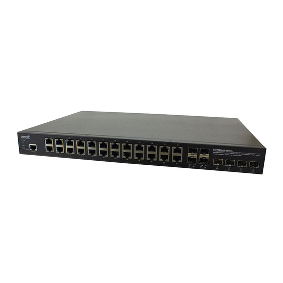
The SISPM1040‐3248‐L delivers 24 (10M/100M/1G) RJ45/PoE+
(support 802.3at/af, and total up to 250W/370W) ports, 4 GbE SFP
ports, 2/4 GbE/10G SFP+ ports and one RJ45 Console port.
The SISPM1040‐3166‐L provides (16) 10/100/1000Base‐T PoE+ ports, (4) 100/1000Base‐X SFP/RJ‐45 Combo and (2)
1G/10G SFP+ ports.
See the SISPM1040‐3xxx‐L Install Guide for important Safety Warnings & Cautions, Features, Specs, Software features,
Front panel, LEDs, Mounting, Connecting, Installing, Power Supply, Initial config, and Troubleshooting.
Package Contents: Make sure you have received: one Switch with one Power Supply installed, one DB‐9 to RJ45 Cable,
AC Power cord (Option), four rubber feet, this manual, and Rack Mount Brackets.
LED Descriptions: The front panel LEDs display switch status. The three types of LEDs are:
System LED: Indicates if the switch is powered up correctly or if there is a system alarm triggered.
Power LEDs (P1/P2: DC LED, P3: AC LED): Indicate if the switch is powered up correctly.
Port Status LEDs: Indicate the current status of each port.
Reset button: Press to toggle the LED indicators to display Link/Activity/Speed or just display PoE port status.
Press the Reset button for 2 ~ 7 seconds to reset the switch (reboot and get the switch back to the previously saved
configuration settings). Press the Reset button for 7 ~ 12 seconds to restore the switch to factory defaults (restore the
switch to its original factory default settings. See the Install Guide.
Back Panel: provides 52‐57 VDC and 100‐250 VAC power inputs and DI/DO relay as shown below.
19‐inch Rack Mounting: 1. Attach the mounting brackets to both sides of the chassis. Insert screws and tighten with a
screwdriver to secure the brackets. 2. Place the switch on a rack shelf in the rack and push it in until the oval holes in the
brackets align with the mounting holes in the rack posts. 3. Attach the brackets to the posts; insert screws and tighten.
Desk or Shelf Mounting: 1. Verify that the workbench is sturdy and reliably grounded. 2. Attach the four adhesive
rubber feet to the bottom of the switch.
Installing SFP Modules: You can install or remove a Hardened SFP/SFP+ Module from an SFP port without powering off
the switch. Note: Use UL Listed Optional Transceiver product, Rated 3.3Vdc, Laser Class 1. 1. Make sure the SFP is
oriented correctly. 2. Insert the module into the SFP port. 3. Press firmly to ensure that the module seats into the
connector. Connecting PDs: See the Install Guide for PSEout requirements.
ATTENTION:
This case must be earth grounded. No DC input may be earth grounded.
Use Isolated Power Supply.
Caution: The switch is an indoor device. If it used with outdoor devices such as outdoor IP cameras, you are strongly
suggested to install a surge protector or surge suppressor to protect the switch. See the Install Guide.
33761 Rev. B
WARNING:
Hot Surface Do Not Touch.
https://www.transition.com
SISPM1040‐3xxx‐L Quick Start Guide
Page 1 of 2
Advertisement
Table of Contents

Related Manuals for Transition Networks SISPM1040-3 L Series


Summary of Contents for Transition Networks SISPM1040-3 L Series
- Page 1 SISPM1040‐3xxx‐L Quick Start Guide SISPM1040‐3xxx‐L Quick Start Guide The SISPM1040‐3248‐L delivers 24 (10M/100M/1G) RJ45/PoE+ (support 802.3at/af, and total up to 250W/370W) ports, 4 GbE SFP ports, 2/4 GbE/10G SFP+ ports and one RJ45 Console port. The SISPM1040‐3166‐L provides (16) 10/100/1000Base‐T PoE+ ports, (4) 100/1000Base‐X SFP/RJ‐45 Combo and (2) 1G/10G SFP+ ports. See the SISPM1040‐3xxx‐L Install Guide for important Safety Warnings & Cautions, Features, Specs, Software features, Front panel, LEDs, Mounting, Connecting, Installing, Power Supply, Initial config, and Troubleshooting. Package Contents: Make sure you have received: one Switch with one Power Supply installed, one DB‐9 to RJ45 Cable, AC Power cord (Option), four rubber feet, this manual, and Rack Mount Brackets. LED Descriptions: The front panel LEDs display switch status. The three types of LEDs are: System LED: Indicates if the switch is powered up correctly or if there is a system alarm triggered. Power LEDs (P1/P2: DC LED, P3: AC LED): Indicate if the switch is powered up correctly. Port Status LEDs: Indicate the current status of each port. Reset button: Press to toggle the LED indicators to display Link/Activity/Speed or just display PoE port status. Press the Reset button for 2 ~ 7 seconds to reset the switch (reboot and get the switch back to the previously saved configuration settings). Press the Reset button for 7 ~ 12 seconds to restore the switch to factory defaults (restore the switch to its original factory default settings. See the Install Guide. Back Panel: provides 52‐57 VDC and 100‐250 VAC power inputs and DI/DO relay as shown below. 19‐inch Rack Mounting: 1. Attach the mounting brackets to both sides of the chassis. Insert screws and tighten with a screwdriver to secure the brackets. 2. Place the switch on a rack shelf in the rack and push it in until the oval holes in the brackets align with the mounting holes in the rack posts. 3. Attach the brackets to the posts; insert screws and tighten. ...
- Page 2 SISPM1040‐3xxx‐L Quick Start Guide Power Supplies: See the Install Guide. Connecting Power: The SISPM1040‐3248‐L/SISPM1040‐3166‐L has one AC power input and Dual DC power inputs. It doesn’t support a secondary AC Power Supply option. It provides redundancy between AC and dual DC power inputs and the AC power input has higher priority. The switch can use DC and AC at the same time. For redundancy, AC takes priority over DC. Connecting the AC Power Cord: You can order one AC Power cord as a separate option. 1. Connect the AC power cord to the AC power receptacle of switch. 2. Connect the other end of the AC power cord to the AC power outlet. 3. Check the SYS LED. If it is On, the power connection is correct. Connecting the DC Power Cord: 1. Insert the negative/positive DC wires into the V‐/V+ terminals, respectively. 2. To keep the DC wires from pulling loose, use a small flat‐blade screwdriver to tighten the wire‐clamp screws on the front of the terminal block connector. 3. Check the SYS LED; if it is lit, the power connection is correct. Initial Switch Configuration via Web Browser: After powering up the switch for the first time, you can perform the initial switch configuration using a web browser. For managing other switch features, see the Web User Guide for details. 1. Reconfigure your PC’s IP address and subnet mask so as to make sure the PC can communicate with the switch. 2. Access the switch Web UI using the default IP address (192.168.1.77). The factory default Subnet Mask is 255.255.255.0. If your PC is configured correctly, you will see the Login page. 3. Enter the factory default username (admin) and password (admin) on login page and click “Login” to log into the switch. See the Web User Guide for more information. Initial Switch Configuration via CLI: 1. Use an RJ‐45 cable to connect a terminal or PC/terminal emulator to the switch port to access the CLI. 2. Attach the RJ‐45 serial port on the switch front panel to the cable for Telnet/CLI configuration. 3. Attach the other end of the DB‐9 cable to a PC running Telnet or a terminal emulation program such as HyperTerminal or TeraTerm. 4. After you power up the switch for the first time, you can perform initial switch configuration using the CLI. See the CLI Reference for more information. ...
Need help?
Do you have a question about the SISPM1040-3 L Series and is the answer not in the manual?
Questions and answers