
Related Manuals for Transition Networks S4224


Summary of Contents for Transition Networks S4224
- Page 1 S4224 Managed 10 Gigabit Ethernet Access/Aggregation Switch Web User Guide 33558 Rev. C 33558 Rev. C https://www.transition.com Page 1 of 669...
-
Page 2: Contact Information
Anyone using this product in such an application without express written consent of an officer of Transition Networks does so at their own risk, and agrees to fully indemnify Transition Networks for any damages that may result from such use or sale. -
Page 3: Table Of Contents
Pool Setting ............................. 36 Configuration > DHCP > DHCP Snooping .................... 41 Configuration > DHCP > DHCP Relay ....................42 S4224 DHCP Configuration Process ......................44 A. At Configuration > System > IP ..................... 44 B. At Configuration > DHCP ....................... 44 Web Interface Screen Examples...................... - Page 4 Transition Networks S4224 Web User Guide SNMP v2 Traps ........................... 70 SNMP v3 Traps ........................... 70 SNMP v3 Configuration Process ......................70 SNMP System Configuration ........................71 SNMP Trap Configuration ........................72 SNMP Trap Event ............................ 74 Specific Trap Event Configuration ...................... 75 SNMPv3 Community Configuration ......................
- Page 5 Transition Networks S4224 Web User Guide VLAN Mode Configuration ....................... 131 Static ARP Inspection ..........................132 Dynamic ARP Inspection ........................134 AAA Security Configuration ......................136 Config > Security > AAA > RADIUS ......................137 Global Configuration ........................137 Server Configuration ........................138 Config >...
- Page 6 Transition Networks S4224 Web User Guide LLDP Configuration ..........................194 LLDP Parameters ..........................195 LLDP Interface Configuration ......................195 LLDP-MED Configuration ........................197 Fast Start Repeat Count ........................197 Transmit TLVs ........................... 198 Coordinates Location ........................198 Civic Address Location ........................199 Emergency Call Service........................
- Page 7 Transition Networks S4224 Web User Guide Static MAC Table Configuration......................262 VLAN Translation Configuration ..................... 264 Port to Group Mapping ........................264 VLAN Translation Mapping ........................266 VLANs Configuration ........................268 Global VLAN Configuration....................... 268 Port VLAN Configuration ........................269 VLAN Name Configuration .......................
- Page 8 Transition Networks S4224 Web User Guide RED Drop Probability Function ......................347 Mirroring & Remote Mirroring Configuration .................. 348 Mirroring & Remote Mirroring Configuration ..................349 Source VLAN(s) Configuration ......................349 Port Configuration (Remote Mirroring) ................... 349 Configuration Guideline for All Features..................350 PTP Clock Configuration .........................
- Page 9 Transition Networks S4224 Web User Guide Monitor > DHCP > Relay Statistics ....................416 Monitor > DHCP > Detailed Statistics ....................418 Receive and Transmit Packets ......................419 Monitor > Security > Access Management ................... 421 Monitor > Security > Network > Port Security ..................422 Port Security >...
- Page 10 Transition Networks S4224 Web User Guide Monitor > Ethernet Services ......................... 490 Service Frame (Traffic) Colors - Green / Yellow / Red ..............490 > EVC Statistics ..........................490 ECE Statistics ............................ 492 Monitor > Performance Monitor ......................494 Performance Monitor Loss Measurement Statistics ................ 494 Performance Monitor Delay Measurement Statistics ..............
- Page 11 Appendix B - Licenses ........................603 Appendix C: Application Notes ...................... 615 S4224 Applications Support ......................... 615 Available TN S4224 Application Notes ..................... 615 Appendix D: Service, Warranty & Compliance Information ............. 616 Appendix E: SNMP Traps and MIBs ....................617 MIBs Supported ............................
- Page 12 Transition Networks S4224 Web User Guide Glossary............................632 Index ............................. 668 Figures Figure 1.SNMP v3 Users, Groups, and Views ....................69 Figure 2. Spanning Tree Example ......................157 Figure 3. Multiple Spanning Tree Example ....................157 Figure 4. 802.1Q EtherTypes (excerpt from IEEE 802.1ad 2005) .............. 274 Figure 5.
-
Page 13: Introduction
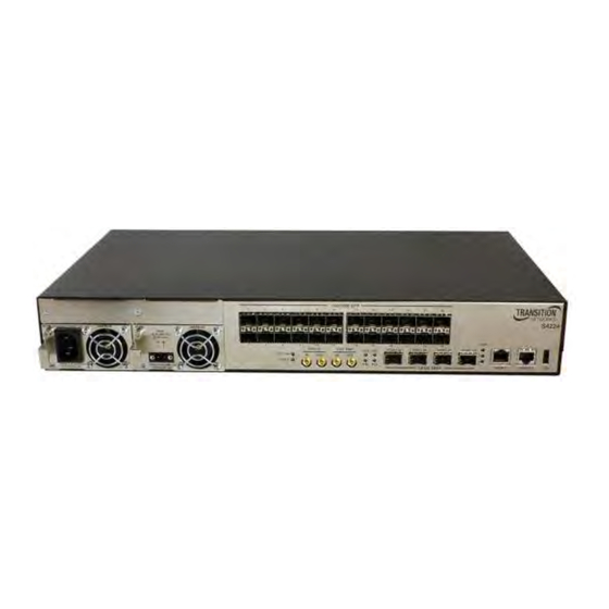
1. Introduction The S4224 switch is a 1RU height product and can be mounted in a 19” rack mount. The S4224 has a hot swappable fan. The S4224 can have one or two hot-swappable power supplies, either AC or DC. -
Page 14: Web Interface Menu System
Transition Networks S4224 Web User Guide 2. Web Interface Menu System The S4224 Web interface menu system is shown below in terms of its sub-menus and functions. Main Menu Configuration Monitor Diagnostics sub- Maintenance sub- sub-menu sub-menu menu menu The four Main menu selections are: Configuration - lets you define system operating parameters for the available S4224 features. - Page 15 Logout Show Help Home: Displays the S4224 Startup Screen from the Monitor > Ports > State menu path. Logout: Display the confirmation message “Do you want to log out of the web site?”. Click the OK button to clear the web page message, perform a logout, and re-display the login (Username/Password) screen.
-
Page 16: Configuration Main Menu
Configuration Main Menu Configuration > System The S4224 system information is configured from the Configuration > System menu path. Here you can configure S4224 device level Information, IP, NTP, time, and logging. The S4224 system information parameters are explained below. -
Page 17: Character Support Note
Character Support Note The S4224 supports the Space * < > : % / \ “ ? |, and all other keyboard characters. The S4224 supports an individual "dot" character, but does not support consecutive dots (e.g., it supports A.B.C.bin, but does not support ABC….bin). -
Page 18: Ip Configuration
Transition Networks S4224 Web User Guide IP Configuration Configure IP basic settings, control IP interfaces and IP routes from the Configuration > System > IP menu path. The maximum number of interfaces supported is 128 and the maximum number of routes is 32. -
Page 19: Dns Proxy
Transition Networks S4224 Web User Guide DNS Proxy When DNS proxy is enabled, system will relay DNS requests to the currently configured DNS server, and reply as a DNS resolver to the client devices on the network. Only IPv4 DNS proxy is now supported. -
Page 20: Ipv6 Address
Transition Networks S4224 Web User Guide IPv6 Address The IPv6 address of the interface. An IPv6 address is in 128-bit records represented as eight fields of up to four hexadecimal digits with a colon separating each field (:). For example, fe80::215:c5ff:fe03:4dc7. - Page 21 When DNS Proxy is enabled, the S4224 will relay DNS requests to the currently configured DNS server on the S4224, and reply as a DNS resolver to the client device on the network. Note that setting these fields does not provide the full set of IP, BootP, VLAN, DNS server, and Management VLAN / member ports configuration.
- Page 22 Transition Networks S4224 Web User Guide Message: No any network address/netmask input. Please enable DHCP or give a valid IPv4 or IPv6 network address and netmask. Recovery: 1. Click the OK button to clear the message. 2. Re-enter a parameter per the instructions.
-
Page 23: Ntp Configuration
NTP uses UDP (datagrams) as transport layer. The S4224 uses NTP for real time clock synchronization with the network time server. The NTP is compliant with RFC 5905. The S4224 takes care of daylight saving options where used. -
Page 24: Time Configuration
Transition Networks S4224 Web User Guide Time Configuration This page allows you to configure the Time Zone and Daylight Savings Time (DST) parameters from the Configuration > System > Time menu path. The Time Zone and Daylight Savings Time (DST) parameters are described below. - Page 25 Transition Networks S4224 Web User Guide Recurring Configurations Start Time Settings Week - Select the starting week number (1-5). Day - Select the starting day ( , or Month - Select the starting month ( , or Hours - Select the starting hour (0 - 23).
-
Page 26: Time Zones List
Transition Networks S4224 Web User Guide Time Zones List The various Time Zone selections available worldwide are listed below. None (GMT-12:00) International Date Line West (GMT-11:00) Midway Island, Samoa (GMT-10:00) Hawaii (GMT-09:00) Alaska (GMT-08:00) Pacific Time (US and Canada) (GMT-08:00) Tijuana, Baja California... -
Page 27: Log (System Log) Configuration
Configure System Logging (Syslog) on this page from Configuration > System > Log. The Syslog data is stored in S4224 RAM by default. Syslog data will be lost with an S4224 reboot unless other provisions are made to save it. -
Page 28: Syslog Events
192.168.1.110 15/10 09:00:37.647 <14>1 1970-01-01T00:39:52+00:00 192.168.1.110 syslog - ID15 [S4224-24] Authentication for 'admin' successful via 'http' 192.168.1.110 15/10 09:08:25.635 Note: At S4224 v2.2.9.3 the total number of syslog records stored on the S4224 has been limited to 1000. 33558 Rev. C https://www.transition.com... -
Page 29: Ports Configuration
Configure the FPGA Shared Port on this page. The parameters are: Shared Port (24) Mode This switch contains one port that is 'Shared'. On the S4224 products, port 24 is shared. The Shared Port has two modes. In External mode, the port can work as normal port. -
Page 30: Configuration > Ports > Configuration
Transition Networks S4224 Web User Guide Configuration > Ports > Configuration The S4224 ports can be configured here in terms of speed, flow control, max. frame size, excessive collision control, and port description. The Port Configuration parameters are explained below. -
Page 31: Flow Control
"disabled". Maximum Frame Size Enter the maximum frame size to be allowed for the S4224 port, including FCS. The valid range is 1518-10056 bytes. The default is 10056 bytes for all ports. Excessive Collision Mode Configure port transmit collision behavior: wild card character selects all. - Page 32 Transition Networks S4224 Web User Guide Buttons Save: Click to save changes. Reset: Click to undo any changes made locally and revert to previously saved values. Refresh: Click to refresh the page. Any changes made locally will be undone. Messages : Are you sure you want to switch the mode about the shared port? 33558 Rev.
-
Page 33: Dhcp Configuration
Note: after power up, the S4224 has DHCP enabled. If a DHCP server is available, the S4224 will obtain an IP address from the DHCP server. If no DHCP server is available, after 70 seconds, the S4224 will fall back to the default IP address of 192.168.0.1/24. -
Page 34: Global Mode
Transition Networks S4224 Web User Guide Global Mode Configure operation mode to enable/disable DHCP server per system. Mode Configure the operation mode per system. Possible modes are: Enabled: Enable DHCP server per system. Disabled: Disable DHCP server per system. VLAN Mode Configure operation mode to enable/disable DHCP server per VLAN. - Page 35 Transition Networks S4224 Web User Guide > DHCP Excluded IP This page configures excluded IP addresses. The DHCP server will not allocate these excluded IP addresses to DHCP client. Click the Add IP Range button to display the DHCP Server Excluded IP Configuration entry fields.
-
Page 36: Pool Setting
Transition Networks S4224 Web User Guide > DHCP Pool This page lets you manage DHCP pools. According to the DHCP pool, the DHCP server will allocate IP address and deliver configuration parameters to the DHCP client. Click the Add New Pool button to display the entry fields. - Page 37 Transition Networks S4224 Web User Guide Buttons Add New Pool: Click to add a new DHCP pool. Save: Click to save changes. Reset: Click to undo any changes made locally and revert to previously saved values. Example Click the linked Name (e.g., DSPC100 below) to display the full DHCP Pool Configuration settings.
-
Page 38: Subnet Mask
Transition Networks S4224 Web User Guide Pool Select a DHCP pool to configure the settings. Name Select a DHCP pool by the pool name. Setting Configure the DHCP pool settings. Pool Name Displays the selected pool name. Type Specify which type the pool is. -
Page 39: Hardware Address
Transition Networks S4224 Web User Guide networked computer which relates to the way it resolves NetBIOS names to IP addresses. The node types are: None: no node. B-node: B- node type (0x01 Broadcast). P-node: P- node type (0x02 Peer (WINS only). - Page 40 Transition Networks S4224 Web User Guide Messages Message: Pool type is defined so IP must be inputted. Pool type is defined so subnet mask must be inputted. Client identifier type is defined so value must be inputted. The value of Broadcast Address, 222.333.444.555, must be a valid IP address in dotted decimal notation (“x.y.z.w”), where x, y, z, and w are decimal numbers between 0 and 255.
-
Page 41: Configuration > Dhcp > Dhcp Snooping
Transition Networks S4224 Web User Guide Configuration > DHCP > DHCP Snooping Configure DHCP Snooping on this page. DHCP Snooping is used to block an intruder on the untrusted switch ports when it tries to intervene by injecting a bogus DHCP reply packet to a legitimate conversation between the DHCP client and server. -
Page 42: Configuration > Dhcp > Dhcp Relay
Transition Networks S4224 Web User Guide Configuration > DHCP > DHCP Relay A DHCP relay agent is used to forward and to transfer DHCP messages between the clients and the server when they are not in the same subnet domain. It stores the incoming interface IP address in the GIADDR field of the DHCP packet. - Page 43 Transition Networks S4224 Web User Guide Buttons Save: Click to save changes. Reset: Click to undo any changes made locally and revert to previously saved values. Messages Message Please make sure the DHCP server connected on trust port? Meaning: A warning message to make sure that the DHCP Server is connected on a port that is configured as “trusted”.
-
Page 44: S4224 Dhcp Configuration Process
Transition Networks S4224 Web User Guide S4224 DHCP Configuration Process Notes: 1. Software releases supporting DHCP Server: S3290 v 2.1.x and S42240, S4140 v 2.2.x. 2. To configure DHCP server you must have a VLAN interface setup with a valid IP address. -
Page 45: Web Interface Screen Examples
Transition Networks S4224 Web User Guide 7. Configure DHCP Options: set DHCP Forwarding Configuration as required. 8. Once the server has been configured check Monitor > DHCP pages for activity on the server. The counters under the Statistics page and the Bindings page allow you to click on each IP address the server has handed out and view its associated MAC address. - Page 46 Transition Networks S4224 Web User Guide B. Configuration > DHCP > Server > Pool B. Configuration > DHCP > Server > Pool Click on linked Pool Name once added. 33558 Rev. C https://www.transition.com Page 46 of 669...
-
Page 47: Additional Notes
5. The maximum number of Pools/addresses that can be served per Port depends on available memory on the device, so simpler setups can handle more IP addresses; devices with more memory can handle more IP addresses (the S3290 has 82MB; the S4224 has 73MB). DHCP Options Used See the IANA web site at http://www.iana.org/assignments/bootp-dhcp-parameters/bootp-dhcp-... - Page 48 Transition Networks S4224 Web User Guide Vendor i Class Identifier: DHCP option 60. Specify to be used by DHCP client to optionally identify the vendor type and configuration of a DHCP client. DHCP server will deliver the corresponding option 43 specific information to the client that sends option 60 vendor class identifier.
-
Page 49: System Users Configuration
The Configuration > Security > Switch > Users menu path lets you view and configure the system users that are allowed to access the web pages or log in from CLI. You can also access the S4224 System Password page from the Configuration > Security > Switch > Users menu path. -
Page 50: Edit User (Edit The Default Admin User)
Transition Networks S4224 Web User Guide Edit User (Edit the Default admin User) To edit the default admin user, click the admin link to display the Edit User page. This page lets you configure the system password required to access the web pages or log in from CLI. -
Page 51: Delete An Existing User
Transition Networks S4224 Web User Guide Privilege Level The privilege level of the user. The allowed range is 1 to 15. If the privilege level value is 15, it can access all groups, i.e. that is granted the fully control of the device. But other values may be needed to refer to each group privilege level. -
Page 52: Privilege Levels Configuration
This page lets you view and edit users’ privilege (access) levels from the Configuration ->Security > Switch > Privilege Levels menu path. Note: this feature only works for web users. The Group Name column lists the S4224 main functions, including Aggregation, DDMI, Debug, DHCP, DHCPv6_Client, Diagnostics, EPS, ERPS, ETH_LINK_OAM, EtherSAT, EVC, IP, IPMC_Snooping,... - Page 53 Transition Networks S4224 Web User Guide The Privilege Level parameters are explained below. Group Name The name identifying the privilege group. In most cases, a privilege level group consists of a single module (e.g. LACP, RSTP or QoS), but some groups contain more than one module.
- Page 54 Transition Networks S4224 Web User Guide Message: Must explicitly add case for module ID: %d Meaning: A user privilege level was not defined for a module. Recovery: 1. Define a privilege level for the module (e.g., crw = 10). 33558 Rev. C https://www.transition.com...
-
Page 55: Authentication Method Configuration
Transition Networks S4224 Web User Guide Authentication Method Configuration Configuration > Security > Switch > Auth Method The authentication section allows you to configure how a user is authenticated when he logs into the switch via one of the management client interfaces. Access this page from the Configuration > Security >... -
Page 56: Command Authorization Method Configuration
Transition Networks S4224 Web User Guide Methods that involve remote servers are timed out if the remote servers are offline. In this case, the next method is tried. Each method is tried from left to right and continues until a method either approves or rejects a user. - Page 57 Transition Networks S4224 Web User Guide Buttons Save: Click to save changes. Reset: Click to undo any changes made locally and revert to previously saved values. Messages Warning: When setting first method for ‘telnet’ to other than ‘local’, you may lose ‘telnet’...
- Page 58 Transition Networks S4224 Web User Guide A sample Auth Method config screen is shown below: Note that AAA is also configurable from the Configuration > Security > AAA > TACACS+.menu path. 33558 Rev. C https://www.transition.com Page 58 of 669...
-
Page 59: Ssh Configuration
Transition Networks S4224 Web User Guide SSH Configuration Configure SSH on this page from the Configuration - Security - Switch - SSH menu path. The SSH (Secure Shell) network protocol allows data to be exchanged using a secure channel between two networked devices. -
Page 60: Https Configuration
HTTPS provides authentication and encrypted communication. The S4224 has an embedded web server for managing the device without any additional software. The web server also provides a secure interface using HTTPS. The validity period will be based on the validity period of the uploaded cert. -
Page 61: File Upload
Transition Networks S4224 Web User Guide Certificate Maintain This field only can be configured when HTTPS is disabled. It is used to maintain the certification. Possible actions are: None: No action for certification. Delete: To delete a certification. Upload: To upload a certification, there are two kind of upload method can be selected: Web Browser or URL. - Page 62 Transition Networks S4224 Web User Guide Certificate upload via Web Browser (No File Selected): Certificate upload via Web Browser (File Selected): Certificate upload via URL (valid path format shown in URL field): Switch secure HTTP certificate is generating ...: 33558 Rev. C https://www.transition.com...
- Page 63 Transition Networks S4224 Web User Guide Messages Message: conf_sec_open failed , creating defaults version mismatch, creating defaults version mismatch (upgrade). Retaining the existing certificate. HTTPS invalid certificate HTTPS invalid URL parameter Meaning: An invalid HTTPS configuration was detected. Recovery: 1. Clear the error message. 2. Re-configure the HTTPS / certificate using the procedures above.
-
Page 64: Access Management Configuration
Management. You can add up to 16 entries. If the application's type matches any one of the access management entries, it will allow access to the S4224. Click the Add New Entry button to start configuring a new Access Management entry. Note: Save each new entry individually. - Page 65 Transition Networks S4224 Web User Guide HTTP/HTTPS Check to allow the host access to the S4224 from the HTTP/HTTPS interface if the host IP address matches the IP address range provided in the entry. SNMP When checked, indicates that the host can access the switch from SNMP interface if the host IP address matches the IP address range provided in the entry.
-
Page 66: Snmp Configuration
SNMP. The SNMP agent embedded in the S4224 is capable of version 1, 2c, or v3 support to access all management information from the device. The community strings for v1 and v2c and the USM/VACM for SNMPv3 are supported. - Page 67 Transition Networks S4224 Web User Guide SNMPv3 Simple Network Management Protocol Version 3 (SNMPv3) is an interoperable standards-based protocol for network management. SNMPv3 provides secure access to devices by a combination of authenticating and encrypting packets over the network. Although SNMPv3 makes no changes to the protocol aside from the addition of cryptographic security, its developers have managed to make things look much different by introducing new textual conventions, concepts, and terminology.
- Page 68 Note: the concept of SNMP communities that was introduced in SNMPv2 is not relevant to SNMPv3, and has been replaced by SNMP groups/users. However, you can configure an S4224 to respond to both SNMPv2 and SNMPv3 commands. If both SNMPv2 and SNMPv3 are to be used, you must configure SNMP communities and SNMP groups and users.
-
Page 69: Figure 1.Snmp V3 Users, Groups, And Views
Transition Networks S4224 Web User Guide Summary: You can create multiple Views. You can then create multiple Groups, and associate them with a View. You can configure multiple Groups (each with a different Group name and security level) and associate them with a particular View. You can also configure more than one View associated with a Group (e.g., a Group with read access to the entire MIB tree, but with only write access to certain... -
Page 70: Snmp V1 Traps
NMS packages. SNMP v2 Traps All S4224 SNMP Trap messages conform to SNMPv2 MIB RFC-2573. See the “Supported MIBs” section on page Error! Bookmark not defined. for information on support for public (standard) and private MIBs. -
Page 71: Snmp System Configuration
Transition Networks S4224 Web User Guide SNMP System Configuration The default Configuration > Security > Switch > SNMP > System page is shown below. Note that the SNMP parameters displayed will vary depending on the SNMP Trap version selected. The Configuration > Security > Switch > SNMP > System parameters are explained below. -
Page 72: Snmp Trap Configuration
Transition Networks S4224 Web User Guide Engine ID Indicates the SNMPv3 engine ID. The string must contain an even number (in hexadecimal format) with number of digits between 10 and 64, but all-zeros and all-'F's are not allowed (e.g., 800007e5017f000001). Changing the Engine ID clears (deletes) all original local users. This field is grayed out unless ‘SNMP V3’... -
Page 73: Trap Community
Transition Networks S4224 Web User Guide Trap Config Name Indicates which trap Configuration's name for configuring. The allowed string length is 1 to 32, and the allowed content is ASCII characters from 33 to 126. Trap Mode Sets the SNMP trap mode operation. The valid selections are: Enabled: Enable SNMP trap mode operation. -
Page 74: Snmp Trap Event
Transition Networks S4224 Web User Guide Trap Inform Retry Times Sets the SNMP trap inform retry times. Not configurable in SNMP v1 mode. The valid range is 0 - 255. The default is 5. Trap Probe Security Engine ID Sets the SNMP V3 trap probe security engine ID mode of operation. The valid values are: Enabled: Enable SNMP trap probe security engine ID mode of operation (default). -
Page 75: Specific Trap Event Configuration
Transition Networks S4224 Web User Guide Switch Indicates that the Switch group's traps. Possible traps are: STP: Enable/disable STP trap. RMON: Enable/disable RMON trap. Specific Trap Event Configuration If you select the ‘specific’ radio button for the SNMP Trap Events ‘Link up’, ‘Link down’, and ‘LLDP’, the port-specific table displays. - Page 76 Transition Networks S4224 Web User Guide Messages Message: The value of “Trap Destination Address’ is 0.0.0.0. Do you want to proceed anyway? Message: After saving configuration, remember select the correct trap security name Recovery: 1. Click the OK button to clear the message. 2. Enter the parameter as described above.
-
Page 77: Snmpv3 Community Configuration
Transition Networks S4224 Web User Guide SNMPv3 Community Configuration Configure SNMPv3 community table on this page from the Configuration > Security > Switch > SNMP > Communities menu path. The entry index key is Community. SNMP V1 and V2c use a community string match for authentication. -
Page 78: Snmpv3 User Configuration
Transition Networks S4224 Web User Guide SNMPv3 User Configuration Configure SNMPv3 user table on this page from the Configuration - Security - Switch - SNMP > User menu path. The entry index keys are Engine ID and User Name. The USM is supported per standard with a variety of user access levels and privacy protocols. -
Page 79: Authentication Protocol
Transition Networks S4224 Web User Guide Authentication Protocol Indicates the authentication protocol that this entry should belong to. Possible authentication protocols are: None: No authentication protocol. MD5: An optional flag to indicate that this user uses MD5 authentication protocol. SHA: An optional flag to indicate that this user uses SHA authentication protocol. -
Page 80: Snmpv3 Group Configuration
Transition Networks S4224 Web User Guide SNMPv3 Group Configuration Configure SNMPv3 group table on this page from the Configuration > Security > Switch > SNMP > Group menu path. The entry index keys are Security Model and Security Name. SNMP v3 configuration involves setting up SNMP v3 Users, Groups, and Views. SNMP Groups are basically access control policies to which users can be added. -
Page 81: Snmpv3 Views Configuration
Transition Networks S4224 Web User Guide SNMPv3 Views Configuration Configure SNMPv3 view table on this page from the Configuration > Security > Switch > SNMP > Group menu path. The entry index keys are View Name and OID Subtree. SNMP v3 configuration involves setting up SNMP v3 Users, Groups, and Views. SNMP MIB Views are defined lists of objects within a MIB that can be used to control which parts of a MIB can be accessed by Users belonging to the SNMP Group associated with that particular View. -
Page 82: Snmpv3 Access Configuration
Transition Networks S4224 Web User Guide SNMPv3 Access Configuration Configure the SNMPv3 access table on this page from the Configuration > Security > Switch > SNMP > Access menu path. The entry index keys are Group Name, Security Model and Security Level. - Page 83 Transition Networks S4224 Web User Guide Buttons Add New Entry: Click to add a new access entry to the table. Add the Group Name, Security Model, Security Level, Read View Name, and Write View Name as described above. Save: Click to save changes.
-
Page 84: Configuration > Security > Switch > Rmon
Configuration > Security > Switch > RMON Configure RMON Statistics, History, Alarms, and Events from the Configuration > Security > Switch > RMON menu path. The S4224 RMON (Remote Network Monitoring) function supports the monitoring and protocol analysis of a LAN per IETF RFC 1271. -
Page 85: Rmon > History
Transition Networks S4224 Web User Guide RMON > History The Configuration > Security > Switch > RMON > History menu path displays the RMON History Configuration table. Configure RMON History table on this page. The entry index key is ID. - Page 86 Transition Networks S4224 Web User Guide Buttons Add New Entry: Click to add a new community entry to the table. Enter the ID, Data Source, Interval, Buckets, and Buckets Granted parameters. Save: Click to save changes. Reset: Click to undo any changes made locally and revert to previously saved values.
-
Page 87: Rmon > Alarm
Transition Networks S4224 Web User Guide RMON > Alarm The Configuration > Security > Switch > SNMP > RMON > Alarm menu path displays the RMON Alarm Configuration table. Configure RMON Alarm table on this page. The entry index key is ID. - Page 88 Transition Networks S4224 Web User Guide Sample Type The method of sampling the selected variable and calculating the value to be compared against the thresholds, possible sample types are: Absolute: Get the sample directly. Delta: Calculate the difference between samples (default).
-
Page 89: Rmon > Event
Transition Networks S4224 Web User Guide RMON > Event The Configuration > Security > Switch > SNMP > RMON > Event menu path displays the RMON Alarm Configuration table. Configure RMON Event table on this page. The entry index key is ID. - Page 90 Transition Networks S4224 Web User Guide An RMON Event Configuration table with four entries is shown below (IDs 1-4). Note that you can monitor the related RMON Statistics, History, Alarm, and Event data from the Monitor > Security > Switch > RMON > Event menu path.
-
Page 91: Port Security Limit Control Configuration
System Configuration Mode Indicates if Limit Control is globally enabled or disabled on the S4224. If globally disabled, other modules may still use the underlying functionality, but limit checks and corresponding actions are disabled. Aging Enabled If checked, secured MAC addresses are subject to aging as discussed under ‘Aging Period’... -
Page 92: Port Configuration
The maximum number of MAC addresses that can be secured on this port. Enter a number from 1 - 1024. If this limit is exceeded, the corresponding action is taken. The S4224 is "born" with a total number of MAC addresses from which all ports draw whenever a new MAC address is seen on a Port Security-enabled port. - Page 93 There are three ways to re-open the shutdown port: 1) Boot the S4224. 2) Disable and re-enable Limit Control on the port or the S4224, or 3) Click the Reopen button. Trap & Shutdown: If ‘Limit’ + 1 MAC addresses is seen on the port, both the "Trap" and the "Shutdown"...
-
Page 94: Nas (Network Access Server) Configuration
MAC-based authentication less secure than 802.1X authentication. IEEE 802.1X Port-based Network Access Control provides a standard for authenticating and authorizing devices attached to a LAN port. Generally, IEEE 802.1X is port-based; however, the S4224 also supports MAC-based network access control. -
Page 95: Nas System Configuration
S4224 Web User Guide NAS System Configuration Mode Indicates if NAS is globally enabled or disabled on the S4224. If globally disabled, all ports are allowed forwarding of frames. Reauthentication Enabled If checked, successfully authenticated supplicants/clients are reauthenticated after the interval specified by the Reauthentication Period. - Page 96 Transition Networks S4224 Web User Guide In MAC-based Auth. mode, the switch will ignore new frames coming from the client during the hold time. The Hold Time can be set to a number between 10 and 1000000 seconds. RADIUS-Assigned QoS Enabled RADIUS-assigned QoS provides a means to centrally control the traffic class to which traffic coming from a successfully authenticated supplicant is assigned on the switch.
-
Page 97: Nas Port Configuration
S4224 Web User Guide NAS Port Configuration The table has one row for each S4224 port and a number of columns, which are explained below. Port The port number for which the configuration below applies. The * in the Port column acts as a ‘wild card’... - Page 98 Transition Networks S4224 Web User Guide more than one supplicant is connected to a port, the one that comes first when the port's link comes up will be the first one considered. If that supplicant doesn't provide valid credentials within a certain amount of time, another supplicant will get a chance.
- Page 99 Transition Networks S4224 Web User Guide RADIUS attributes used in identifying a QoS Class: The User-Priority-Table attribute defined in RFC4675 forms the basis for identifying the QoS Class in an Access-Accept packet. Only the first occurrence of the attribute in the packet will be considered, and to be valid, it must follow this rule: •...
- Page 100 Transition Networks S4224 Web User Guide VLAN. The interval between transmissions of EAPOL Request Identity frames is configured with ‘EAPOL Timeout. If Allow Guest VLAN if EAPOL Seen’ enabled, the port will now be placed in the Guest VLAN. If disabled, the switch will first check its history to see if an EAPOL frame has previously been received on the port (this history is cleared if the port link goes down or the port's ‘Admin State...
- Page 101 Transition Networks S4224 Web User Guide Example In the sample Configuration > Security > NAS setup below, Port 3 shows “Single 802.1X”, RADIUS- assigned QoS disabled / VLAN disabled, Guest VLAN enabled, Authorized port state, with “Reauthenticate” and “Reinitialize” restart enabled.
-
Page 102: Acl Ports Configuration
Access Controls Lists The S4224 can ‘peek’ into the frames at line rate and is capable of deep packet inspection; this ability gives a wide range of access controls. The rules or the access control lists can look at any field in the Layer 2 to Layer 4 headers to make the decision of allowing, discarding, mirroring, logging or even shutdown the port that the frame came through. -
Page 103: Evc Policer
Transition Networks S4224 Web User Guide Port The logical port for the settings contained in the same row. The * in the Port column acts as a ‘wild card’ character which causes the selections in this row to be applied to all other rows in the table for which this selection is valid. - Page 104 Transition Networks S4224 Web User Guide Disabled: To close ports by changing the volatile port configuration of the ACL user module. The default value is " Enabled ". Counter A count of the number of frames that match this ACE. This is a read only field.
-
Page 105: Acl Rate Limiter Configuration
S4224 Web User Guide ACL Rate Limiter Configuration Configure the rate limiter for the ACL of the S4224 from the Configuration > Security > Network > ACL > Rate Limiters menu path. The Configuration > Security > Network > ACL > Rate Limiters page parameters are explained below. -
Page 106: Access Control List (Acl) Configuration
The Configuration > Security > Network > ACL > Access Control List menu path displays the Access Control List Configuration table, which is made up of the ACEs defined on this S4224. Each row describes the ACE that is defined. The maximum number of ACEs is 512 on each S4224. -
Page 107: Ace Configuration
Transition Networks S4224 Web User Guide Rate Limiter Indicates the rate limiter number of the ACE. The allowed range is 1 to 16. When Disabled is displayed, the rate limiter operation is disabled. Port Redirect Indicates the port redirect operation of the ACE. Frames matching the ACE are redirected to the port number. - Page 108 Transition Networks S4224 Web User Guide Ingress Port Select the ingress port for which this ACE applies. All: The ACE applies to all port. Port n: The ACE applies to this port number, where n is the number of the switch port.
- Page 109 Transition Networks S4224 Web User Guide Disabled: Frames matching the ACE are not logged. Note: The logging feature only works when the packet length is less than 1518 (without VLAN tags) and the System Log memory size and logging rate is limited.
- Page 110 Transition Networks S4224 Web User Guide When you click the button to edit an existing ACE row, the ACE row edit screen displays to let you edit the above parameters for an existing ACE entry. The parameters displayed depend on the config selections. For example, the config screen above...
- Page 111 Transition Networks S4224 Web User Guide The configuration screen below displays if you select Frame Type = The configuration screen below displays if you select Frame Type = IPv4 33558 Rev. C https://www.transition.com Page 111 of 669...
- Page 112 Transition Networks S4224 Web User Guide The configuration screen below displays if you select Frame Type = IPv6 The various ACL parameters are explained below. 33558 Rev. C https://www.transition.com Page 112 of 669...
-
Page 113: Ace Configuration Parameters
Transition Networks S4224 Web User Guide ACE Configuration Parameters The ACE Configuration parameters let you configure the Access Control List Configuration table parameters as described earlier in this section. MAC Parameters SMAC Filter Specify the source MAC filter for this ACE. (Only displayed when the frame type is Ethernet Type or ARP.) -
Page 114: Vlan Parameters
Transition Networks S4224 Web User Guide VLAN Parameters VLAN ID Filter Specify the VLAN ID filter for this ACE. Any: No VLAN ID filter is specified. (VLAN ID filter status is "don't- care".) Specific: If you want to filter a specific VLAN ID with this ACE, choose this value. A field for entering a VLAN ID number displays. -
Page 115: Target Ip Address
Transition Networks S4224 Web User Guide Network: Sender IP filter is set to Network. Specify the sender IP address and sender IP mask in the SIP Address and SIP Mask fields that appear. Sender IP Address When "Host" or "Network" is selected for the sender IP filter, you can enter a specific sender IP address in dotted decimal notation. -
Page 116: Ipv4 Parameters
Transition Networks S4224 Web User Guide Specify whether frames can hit the action according to their ARP/RARP hardware address space (HRD) settings. 0: ARP/RARP frames where the HLD is not equal to Ethernet (1). 1: ARP/RARP frames where the HLD is equal to Ethernet (1). - Page 117 Transition Networks S4224 Web User Guide able to match this entry. Any: Any value is allowed ("don't-care"). IP Option Specify the options flag setting for this ACE. No: IPv4 frames where the options flag is set must not be able to match this entry.
-
Page 118: Ipv6 Parameters
Transition Networks S4224 Web User Guide IPv6 Parameters The IPv6 parameters can be configured when Frame Type "IPv6" is selected. Next Header Filter Specify the IPv6 next header filter for this ACE. Any: No IPv6 next header filter is specified ("don't-care"). -
Page 119: Icmp Parameters
Transition Networks S4224 Web User Guide ICMP Parameters ICMP Type Filter Specify the ICMP filter for this ACE. Any: No ICMP filter is specified (ICMP filter status is "don't-care"). Specific: If you want to filter a specific ICMP filter with this ACE, you can enter a specific ICMP value. -
Page 120: Tcp Parameters
Transition Networks S4224 Web User Guide TCP Parameters Source Port Filter Specify the TCP/UDP source filter for this ACE. Any: No TCP/UDP source filter is specified (TCP/UDP source filter status is "don't-care"). Specific: If you want to filter a specific TCP/UDP source filter with this ACE, you can enter a specific TCP/UDP source value. - Page 121 Transition Networks S4224 Web User Guide TCP SYN One of several TCP flag names used only when filtering TCP (urg, ack, psh, rst, syn, and fin). Specify the TCP "Synchronize sequence numbers" (SYN) value for this ACE. 0: TCP frames where the SYN field is set must not be able to match this entry.
-
Page 122: Udp Parameters
Transition Networks S4224 Web User Guide UDP Parameters Source Port Filter Specify the TCP/UDP source filter for this ACE. Any: No TCP/UDP source filter is specified (TCP/UDP source filter status is "don't-care"). Specific: If you want to filter a specific TCP/UDP source filter with this ACE, you can enter a specific TCP/UDP source value. -
Page 123: Ethernet Type Parameters
Transition Networks S4224 Web User Guide Ethernet Type Parameters The Ethernet Type parameters can be configured when Frame Type "Ethernet Type" is selected. EtherType Filter Specify the Ethernet type filter for this ACE. Any: No EtherType filter is specified (EtherType filter status is "don't-care"). -
Page 124: Bandwidth Profile Using Ace (Access Control Entry)
Bandwidth Profile using ACE (Access Control Entry) Apart from MEF specified layer-2 services, the S4224 can associate the bandwidth profile parameters of < CIR, CBS, EIR, EBS, CM, CF> with any kind of traffic flow. The web interface provides the option of Layer 2 to Layer 4 flows to be associated with a bandwidth profile. -
Page 125: Ip Source Guard Configuration
Transition Networks S4224 Web User Guide IP Source Guard Configuration IP Source Guard is a security feature used to restrict IP traffic on DHCP snooping untrusted ports by filtering traffic based on the DHCP Snooping Table or manually configured IP Source Bindings. It helps prevent IP spoofing attacks when a host tries to spoof and use the IP address of another host. -
Page 126: Ip Source Guard > Configuration
Transition Networks S4224 Web User Guide IP Source Guard > Configuration Here you can configure IP Source Guard Mode and Port Mode, and translate all dynamic entries to static entries for both ARP Inspection and Dynamic ARP Inspection. It is also possible to add a new entry to the Static ARP Inspection table and/or IP Source Guard by specifying the Port, VLAN ID, MAC address, and IP address for the new entry. -
Page 127: Ip Source Guard > Static Table
Transition Networks S4224 Web User Guide IP Source Guard > Static Table The default Static IP Source Guard Table displays no saved entries. When you click the Add New Entry button, initial entry fields display. The Static IP Source Guard Table parameters are described below. - Page 128 Transition Networks S4224 Web User Guide Example The Static IP Source Guard Table shown below shows four new saved entries. The example above has Port 1 with two entries with the same VLAN ID, different IP Addresses, and different MAC address. Port 3 has two entries for two different VLAN IDs with the same IP Address, and the same MAC address.
-
Page 129: Arp Inspection Configuration
Transition Networks S4224 Web User Guide ARP Inspection Configuration ARP Inspection is a security feature. Several types of attacks can be launched against a host or devices connected to Layer 2 networks by "poisoning" the ARP caches. The ARP Inspection feature is used to block such attacks. - Page 130 Transition Networks S4224 Web User Guide Permit: Log permitted entries. ALL: Log all entries. Buttons Save: Click to save changes. Reset: Click to undo any changes made locally and revert to previously saved values. Translate dynamic to static: Click to translate all dynamic entries to static entries.
-
Page 131: Vlan Configuration
Transition Networks S4224 Web User Guide VLAN Configuration The Configuration > Security > Network > ARP Inspection > VLAN Configuration menu path provides ARP Inspection related configuration. ARP Inspection is a security feature. Several types of attacks can be launched against a host or devices connected to Layer 2 networks by "poisoning" the ARP caches. -
Page 132: Static Arp Inspection
Transition Networks S4224 Web User Guide Static ARP Inspection The Configuration > Security > Network > ARP Inspection > Static Table menu path provides the default Static ARP Inspection rules. The switch supports a maximum of 256 rules. Click the Add New Entry button to display the entry table. - Page 133 Transition Networks S4224 Web User Guide Example The Static ARP Inspection Table shown below shows three saved entries. Note that you can create multiple entries and then Save them in one Save operation. You can also cut and paste information between fields. Use the keyboard Tab key to move from one field to the next.
-
Page 134: Dynamic Arp Inspection
Transition Networks S4224 Web User Guide Dynamic ARP Inspection The Configuration > Security > Network > ARP Inspection > Dynamic Table menu path displays the Dynamic ARP Inspection Table. The Dynamic ARP Inspection Table contains up to entries, and is sorted first by port, then by VLAN ID, then by MAC address, and then by IP address. - Page 135 Transition Networks S4224 Web User Guide Buttons Auto-refresh: Check this box to refresh the page automatically. Automatic refresh occurs every 3 seconds. Refresh: Refreshes the displayed table starting from the input fields. Save: Click to save changes. Reset: Click to undo any changes made locally and revert to previously saved values.
-
Page 136: Aaa Security Configuration
Transition Networks S4224 Web User Guide AAA Security Configuration This page lets you configure the AAA (Authentication, Authorization and Accounting) Servers. You can configure the optional RADIUS and/or TACACS+ servers from the Configuration > Security > AAA menu path. RADIUS (Remote Authentication Dial In User Service) networking protocol provides centralized access, authorization and accounting management for computers to connect and use a network service. -
Page 137: Config > Security > Aaa > Radius
Transition Networks S4224 Web User Guide Config > Security > AAA > RADIUS The RADIUS Server Configuration page lets you configure RADIUS Global and Server configuration. Click the Add New Server button to display the new RADIUS server config parameters. -
Page 138: Server Configuration
Transition Networks S4224 Web User Guide NAS-IP-Address (Attribute 4) The IPv4 address to be used as attribute 4 in RADIUS Access-Request packets. If this field is left blank, the IP address of the outgoing interface is used. Must be a valid IP v4 address in dotted decimal notation (“x.y.z.w”), where x, y, z, and w are decimal numbers between 0 and 255. -
Page 139: Config > Security > Aaa > Tacacs
Transition Networks S4224 Web User Guide Config > Security > AAA > TACACS+ This page lets you configure the TACACS+ server(s) and global parameters. Click the Add New Server button to add an empty row is added to the table. -
Page 140: Adding A New Server
Transition Networks S4224 Web User Guide Port The TCP port to use on the TACACS+ server for authentication. Timeout This optional setting overrides the global timeout value. Leaving it blank will use the global timeout value. This optional setting overrides the global key. Leaving it blank will use the global key. -
Page 141: Aggregation Configuration
For best traffic distribution among LAG member ports, enable all six contributions to the AC. Each LAG can consist of up to 16 member ports. Any quantity of LAGs may be configured for the S4224 (only limited by the number of device ports). To configure a proper traffic distribution, the ports within a LAG must use the same link speed. -
Page 142: Static Aggregation
Transition Networks S4224 Web User Guide Static Aggregation This page is used to configure the Aggregation hash mode and the aggregation group from the Configuration > Aggregation > Static menu path. Aggregation involves using multiple ports in parallel to increase the link speed beyond the limits of a port, and to increase the redundancy for higher availability (aka ‘Port Aggregation’... -
Page 143: Aggregation Mode Configuration - Hash Code Contributors
Port Members Each S4224 port is listed for each group ID. Select a radio button to include a port in an aggregation, or clear the radio button to remove the port from the aggregation. By default, no ports belong to any aggregation group. - Page 144 Recovery: Verify that all ports are FDX and same speed. The S4224 does not allow ports with different speeds and half duplex to be aggregated. 1. At Configuration > Ports > Configuration, configure Ports at identical speeds and also as Full Duplex.
-
Page 145: Lacp (Link Aggregation Control Protocol)
The S4224 supports Link aggregation per IEEE 802.1AX-2008. The Link aggregation supports several physical links bundled into a single logical link for resiliency and load sharing. The S4224 uses LACP PDUs to negotiate with peer devices and to exchange information about the links to be bundled automatically when enabled on the physical port. - Page 146 Port The S4224 port number. The * in the Port column acts as a ‘wild card’ character which causes the selections in this row to be applied to all other rows in the table for which this selection is valid.
- Page 147 Transition Networks S4224 Web User Guide Role The Role shows the LACP activity status. The Active will transmit LACP packets each second, while Passive will wait for a LACP packet from a partner (i.e., ‘speak if spoken to’). The default is Active.
-
Page 148: Link Oam (Loam) Configuration
802.3ah and also Flow OAM requirements from IEEE 802.1ag as well as the IEEE standards, ITU-T G.1731 and ITU-T G.8021. The S4224 supports Point-to-point link level OAM per 802.3ah to monitor the link operations in both Active and Passive mode. Mechanisms to support the following are implemented: 1. -
Page 149: Link Oam Port Settings
OAM > Port Settings menu path. Port The S4224 port number. Click on a specific port number in the table to display that port’s ‘Detailed Link OAM Status’. The * in the Port column acts as a ‘wild card’ character which causes the selections in this row to be applied to all other rows in the table for which this selection is valid. - Page 150 S4224 Web User Guide MIB Retrieval Support Controls whether the MIB Retrieval Support is enabled for the S4224 port. On enabling MIB retrieval support, the DTE supports polling of various Link OAM based MIB variables' contents. Note that if MIB Retrieval Support is enabled, ‘Loopback Operation’ must be disabled. If both are enabled, the message “OAM Error - Error while configuring the OAM loopback”...
-
Page 151: Link Oam Event Settings
The Link Event Configuration parameters are explained below. Port x The S4224 port number. The port select box determines which port is affected by clicking the buttons. The * in the Port column acts as a ‘wild card’ character which causes the selections in this row to be applied to all other rows in the table for which this selection is valid. - Page 152 Transition Networks S4224 Web User Guide generated if the number of errored frame seconds is equal to or greater than the specified threshold for that period. An errored frame second is a one second interval wherein at least one frame error was detected.
-
Page 153: Detailed Link Oam Status
Transition Networks S4224 Web User Guide Detailed Link OAM Status After a ‘Save’, at the Link OAM Port Configuration page, click on a linked Port number in the “Port” column to display that particular port’s “Detailed Link OAM Status’ information. - Page 154 Transition Networks S4224 Web User Guide MTU Size Represents the largest OAMPDU, in octets, supported by the DTE. This value is compared to the remote’s Maximum PDU Size and the smaller of the two is used (e.g., 1500). Multiplexer State When Forwarding displays, the device is forwarding non-OAMPDUs to the lower sublayer.
-
Page 155: Loop Protection Configuration
The Configuration > Loop Protection menu path lets you view and/or change the current global and port-level Loop Protection configuration. Note: If you will be using the S4224 Loop Protection function, enable Loop Protection here, both globally and at the port level, as one of the first overall configuration steps. - Page 156 The switch port number of the port. Note that loop protection is not supported on the MGMT/data port. Enable Controls whether loop protection is enabled on this S4224 port. Action Configures the action to be performed when a loop is detected on a port. The valid Actions are: Sets the action to be performed when a loop is detected on a port.
-
Page 157: Spanning Tree
802.1D for STP, 802.1w for RSTP and 802.1s for MSTP. The S4224 can act in the role of a root bridge or as a designated bridge by the process of election. The priorities for the bridge instance that is used in BPDU frames can be configured. For MSTP, each MSTI (Multiple Spanning Tree Instance) priority can be configured for the Common and Internal Spanning Tree (CIST) instance. -
Page 158: Bridge Settings
Bridge Settings S4224 STP Bridge configuration is done from the Configuration > Spanning Tree > Bridge Settings menu path. This page lets you configure STP system settings, which are used by all S4224 STP Bridge instances. Basic Settings Protocol Version The STP protocol version setting. -
Page 159: Forward Delay
The bridge priority plus the MSTI instance number, concatenated with the 6-byte MAC address of the S4224 forms a Bridge Identifier. For MSTP operation, this is the priority of the CIST (Common and Internal Spanning Tree). - Page 160 Transition Networks S4224 Web User Guide Buttons Save: Click to save changes. Reset: Click to undo any changes made locally and revert to previously saved values. 33558 Rev. C https://www.transition.com Page 160 of 669...
-
Page 161: Msti Mapping
Transition Networks S4224 Web User Guide MSTI Mapping MSTI (Multiple Spanning Tree Instance) configuration is done from the Configuration > Spanning Tree > MSTI Mapping menu path. MSTP enables the grouping and mapping of VLANs to different spanning tree instances. An MSTI (MST Instance) is a particular set of VLANs that use the same spanning tree. - Page 162 Transition Networks S4224 Web User Guide Buttons Save: Click to save changes. Reset: Click to undo any changes made locally and revert to previously saved values. 33558 Rev. C https://www.transition.com Page 162 of 669...
-
Page 163: Msti Priorities
Sets the bridge priority. Lower numeric values have better priority. The bridge priority plus the MSTI instance number, concatenated with the 6-byte S4224 MAC address forms a Bridge Identifier. Select 0, 4096, 8192, 12288, 16384, 20480, 24576, 28672, 32768, 36864, 40960, 45056, 49152, 53248, 57344, or 61440. -
Page 164: Cist Ports
Port The S4224 port number of the logical STP port. The * in the Port column acts as a ‘wild card’ character which causes the selections in this row to be applied to all other Ports (rows) in the table for which this selection is valid. -
Page 165: Bpdu Guard
Transition Networks S4224 Web User Guide Path Cost Controls the path cost incurred by the port (dropdown and entry field). The Auto setting will set the path cost as appropriate by the physical link speed, using the 802.1D recommended values. This is the default setting. - Page 166 Transition Networks S4224 Web User Guide BPDU Guard is provided as part of the STP Configuration advanced global bridge settings. It controls whether a port explicitly configured as Edge will disable itself upon reception of a BPDU. The port will enter the error-disabled state, and will be removed from the active topology.
-
Page 167: Msti Ports
MSTI port configuration options: This page contains MSTI port settings for physical and aggregated ports. Port The S4224 port number of the corresponding STP CIST (and MSTI) port. Path Cost Controls the path cost incurred by the port. The Auto setting will set the path cost as appropriate by the physical link speed, using the 802.1D recommended values. - Page 168 Transition Networks S4224 Web User Guide Using the Specific setting, a user-defined value can be entered. The path cost is used when establishing the active topology of the network. Lower path cost ports are chosen as forwarding ports in favor of higher path cost ports. Valid values are 1 to 200,000,000.
-
Page 169: Ipmc Profile Configuration
64 Profiles with at maximum 128 corresponding rules for each. Global Profile Mode This dropdown lets you Enable/Disable the Global IPMC Profile. When enabled, the S4224 starts to do filtering based on the profile settings only. When you click the Add New IPMC Profile button the “IPMC Profile [IPMCaddr1]Rule Settings (In Precedence Order)”... -
Page 170: Profile Table
Transition Networks S4224 Web User Guide When you add and save a new IPMC profile, click the Navigate icon to display the Profile table shown below: The Profile table parameters are described below. > Profile Table The “IPMC Profile Rule Settings Table” page provides the filtering rule settings for a specific IPMC profile. - Page 171 Transition Networks S4224 Web User Guide Rule Management Buttons You can manage rules and the corresponding precedence order by using these buttons: : Insert a new rule before the current entry of rule. : Delete the current rule entry. : Moves the current entry of rule up in the list.
-
Page 172: Address Entry
Transition Networks S4224 Web User Guide > Address Entry The Configuration > IPMC Profile > Address Entry menu path displays the “IPMC Profile Address Configuration” page. When you click the Add New Address (Range Entry” button, the editable “IPMC Profile Address Configuration”... - Page 173 Transition Networks S4224 Web User Guide IPMC Profile > Address Entry Example Messages Please input valid IPv4/IPv6 multicast start address for <entry name> Enter valid starting and ending IPv4/IPv6 Multicast Group Addresses. http://www.iana.org/assignments/multicast-addresses/multicast-addresses.xhtml for valid address information. 33558 Rev. C https://www.transition.com...
- Page 174 Transition Networks S4224 Web User Guide IPMC Parameters Summary Configurable Parameter Allowed Range Default Global Profile Mode Enabled/Disabled Disabled Profile name Up to 16 characters blank Profile description Up to 64 characters blank An address entry can be created by specifying a name and a Start and End valid IPv4/IPv6 Multicast address.
-
Page 175: Mvr Configuration
Transition Networks S4224 Web User Guide MVR Configuration This page provides MVR related configurations from the Configuration > MVR menu path. You can view Statistics, MVR Channel Groups, and MVR SFM Information from the Monitor > MVR menu path. Most of the settings are global, whereas the Immediate Leave and MVR Port-Role configuration is related to the current selecting stack unit, as reflected by the page header. - Page 176 Transition Networks S4224 Web User Guide MVR VID Specify the Multicast VLAN ID. Caution: MVR source ports are not recommended to be overlapped with management VLAN ports. MVR Name MVR Name is an optional attribute to indicate the name of the specific MVR VLAN. Maximum length of the MVR VLAN Name string is 16.
-
Page 177: Port Role
Transition Networks S4224 Web User Guide Port The logical port for the settings. Port Role Configure an MVR port of the designated MVR VLAN as one of the following roles. Inactive: The designated port does not participate MVR operations. Source: Configure uplink ports that receive and send multicast data as source ports. Subscribers cannot be directly connected to source ports. -
Page 178: Ipmc (Ip Multicast)
The S4224 also supports IGMP/MLD snooping at VLAN levels. A maximum of 64 VLANs can be chosen for IGMP snooping. Typically the router is the IGMP querier but an option to enable IGMP querier on each VLAN is provided as well on this device. -
Page 179: Igmp Snooping
IGMP snooping allows the S4224 dynamically determine which hosts connected to a particular VLAN in the switch need to receive a particular multicast transmission. The S4224 basically listens (snoops) to the various IGMP messages (e.g., ‘Query’ or ‘Leave’) and other multicast protocol transmissions. It then dynamically determines which egress ports are associated with each multicast transmission. - Page 180 When you enable IGMP fast-leave processing, the S4224 immediately removes a port when it detects an IGMP v2 leave message on that port. Throttling Select unlimited or a value from 1 - 10 to limit the number of multicast groups to which an S4224 port can belong. The default is unlimited. 33558 Rev. C https://www.transition.com...
- Page 181 Transition Networks S4224 Web User Guide Buttons Save: Click to save changes. Reset: Click to undo any changes made locally and revert to previously saved values. 33558 Rev. C https://www.transition.com Page 181 of 669...
-
Page 182: Vlan Configuration
Querier Address Define the IPv4 address as source address used in IP header for IGMP Querier election. When the Querier address is not set, the S4224 uses the IPv4 management address of the IP interface associated with this VLAN. When the IPv4 management address is not set, the S4224 uses the first available IPv4 management address. - Page 183 Transition Networks S4224 Web User Guide Compatibility Select IGMP-Auto, Forced IGMPv1, Forced IGMPv2, or Forced IGMPv3. Compatibility is maintained by hosts and routers taking appropriate actions depending on the versions of IGMP operating on hosts and routers within a network. The default value is IGMP-Auto.
- Page 184 Transition Networks S4224 Web User Guide Buttons Refresh: Refreshes the displayed table starting from the "VLAN" input fields. |<<: Updates the table starting at the first VLAN Table entry (the entry with the lowest VLAN ID). >>: Updates the table, starting with the entry after the last entry currently displayed.
-
Page 185: Port Filtering Profile
Transition Networks S4224 Web User Guide Port Filtering Profile From the Configuration > IPMC > IGMP Snooping > Port Filtering Profile menu path you can view and edit the IGMP Snooping Port Filtering Profile Configuration table. An IPMC (IP MultiCast) Profile is used to deploy the access control on IP multicast streams. -
Page 186: Mld Snooping
Transition Networks S4224 Web User Guide MLD Snooping The MLD Snooping menu provides for Basic Configuration, VLAN Configuration, and Port Group Filtering configuration from the sub-menus from the Configuration > IPMC > MLD Snooping menu path.. Multicast Listener Discovery for IPv6 (MLD) is used by IPv6 routers to discover multicast listeners on a directly attached link, much as IGMP is used in IPv4. - Page 187 Router Port Check to specify which ports act as router ports. A router port is a port on the S4224 that leads towards the Layer 3 multicast device or MLD querier. If an aggregation member port is selected as a router port, the whole aggregation will act as a router port.
- Page 188 When you enable MLD fast-leave processing, the S4224 immediately removes a port when it detects an IGMP v2 leave message on that port. Throttling Used to limit the number of multicast groups to which a S4224 port can belong. Select unlimited or 1-10 multicast groups as the limit. The default is unlimited. Buttons Save: Click to save changes (required to be able to edit all fields).
-
Page 189: Vlan Configuration
Transition Networks S4224 Web User Guide VLAN Configuration From the Configuration > IPMC > MLD Snooping > VLAN Configuration menu path you can view and edit the MLD Snooping VLAN Configuration parameters. Click the Add New MLD VLAN button to display the MLD Snooping VLAN Configuration table. - Page 190 Transition Networks S4224 Web User Guide Compatibility Select MLD-Auto, Forced or Forced MLDv2. Compatibility is maintained by hosts and MLDv1, routers taking appropriate actions depending on the versions of MLD operating on hosts and routers within a network. The default compatibility value is MLD-Auto.
- Page 191 Transition Networks S4224 Web User Guide Buttons Refresh: Refreshes the displayed table starting from the "VLAN" input fields. |<<: Updates the table starting from the first entry in the VLAN Table (i.e., the entry with the lowest VLAN >>: Updates the table, starting with the entry after the last entry currently displayed.
-
Page 192: Port Filtering Profile
Transition Networks S4224 Web User Guide Port Filtering Profile From the Configuration > IPMC > MLD Snooping > Port Filtering Profile menu path you can view and edit the MLD Snooping Port Filtering Profile parameters. The Port Filtering Profile table columns are explained below. -
Page 193: L2Cp Configuration
Transition Networks S4224 Web User Guide L2CP Configuration This page displays current EVC L2CP configurations and lets you configure the settings. For each service, L2CP protocols are configured to ‘peer’, ‘forward’ or ‘discard’. Note that while L2CP configuration is performed from the Configuration > L2CP menu path, the L2CP command applies not just to Ethernet Services, but to all BPDU handling. -
Page 194: Lldp Configuration
Transition Networks S4224 Web User Guide LLDP Configuration The S4224 Configuration > LLDP menu path lets you configure LLDP at the device level and at the port level. The Configuration > LLDP menu path also lets you configure LLDP-MED. LLDP Configuration From the Configuration >... -
Page 195: Lldp Parameters
1/4 of the Tx Interval value. Valid values are 1 - 8192 seconds. The default is 2 seconds. Tx Reinit When a port is disabled, LLDP is disabled or the S4224 is rebooted, an LLDP shutdown frame is transmitted to the neighboring units, signaling that the LLDP information isn't valid anymore. Tx Reinit controls the amount of seconds between the shutdown frame and a new LLDP initialization. - Page 196 Save: Click to save changes. Reset: Click to undo any changes made locally and revert to previously saved values. The S4224 maintains LLDP port and protocol statistics and a table of neighbors that were discovered. See Monitor > LLDP for more information.
-
Page 197: Lldp-Med Configuration
Transition Networks S4224 Web User Guide LLDP-MED Configuration From the Configuration > LLDP > LLDP-MED menu path you can view and edit the LLDP-MED parameters. LLDP-MED is an extension of IEEE 802.1ab and is defined by the telecommunication industry association (TIA-1057). This function applies to VoIP devices which support LLDP-MED. -
Page 198: Transmit Tlvs
Transition Networks S4224 Web User Guide times the fast start transmission would be repeated. The recommended value is 4 times, given that 4 LLDP frames with a 1 second interval will be transmitted, when an LLDP frame with new information is received. -
Page 199: Civic Address Location
Transition Networks S4224 Web User Guide Map Datum The Map Datum is used for the coordinates given in these options: WGS84: (Geographical 3D) - World Geodesic System 1984, CRS Code 4327, Prime Meridian Name: Greenwich. NAD83/NAVD88: North American Datum 1983, CRS Code 4269, Prime Meridian Name: Greenwich; The associated vertical datum is the North American Vertical Datum of 1988 (NAVD88). - Page 200 Transition Networks S4224 Web User Guide House no. House number (e.g., 21). House no. suffix House number suffix (e.g., A, ½). Landmark Landmark or vanity address (e.g., Columbia University). Additional location info Additional location info (e.g., South Wing). Name Name (residence and office occupant) (e.g., Flemming Jahn).
-
Page 201: Emergency Call Service
Transition Networks S4224 Web User Guide Emergency Call Service Emergency Call Service (e.g. E911 and others), such as defined by TIA or NENA. Emergency Call Service Emergency Call Service ELIN identifier data format is defined to carry the ELIN identifier as used during emergency call setup to a traditional CAMA or ISDN trunk-based PSAP. - Page 202 Transition Networks S4224 Web User Guide Policy ID ID for the policy. This is auto generated and shall be used when selecting the policies that shall be mapped to the specific ports. Application Type Intended use of the application types: 1.
-
Page 203: Adding A New Policy
Transition Networks S4224 Web User Guide DSCP DSCP value to be used to provide Diffserv node behaviour for the specified application type as defined in IETF RFC 2474. DSCP may contain one of 64 code point values (0 - 63). A value of 0 represents use of the default DSCP value as defined in IETF RFC 2475. -
Page 204: Eps Configuration
Transition Networks S4224 Web User Guide EPS Configuration The Ethernet (Linear) Protection Switch (EPS) instances are configured from the Configuration > EPS menu path. Linear Protection is implemented for maintaining connectivity via alternate path in case the current data path fails. Two or more parallel instances are configured between ports of a unit pair. Two of the paths are configured into an Ethernet Protection switching group as a pair of Working-Protecting instances. - Page 205 Transition Networks S4224 Web User Guide Architecture Select the linear protection switching architecture; either 1+1 protection switching or 1:1 protection switching architecture. 1+1: This will create a 1+1 EPS. The linear 1+1 protection switching architecture operates with either unidirectional or bidirectional switching. In a 1+1 architecture, a protection transport entity is used to protect the normal traffic signal.
-
Page 206: Eps Configuration
Transition Networks S4224 Web User Guide EPS Configuration When you click on the ID of an EPS, its configuration page displays. For example, if you click on EPS ID 2 on the screen above, the EPS ID 2 configuration screen displays: This screen lets you configure the EPS Instance Data, Instance Configuration, and Instance Command parameters as well as display the current Instance State. -
Page 207: Eps Instance Configuration
Transition Networks S4224 Web User Guide EPS Instance Configuration If configured, the possible Protection Types are: 1+1 Unidirectional, no APS communication. 1+1 Unidirectional with APS communication. 1+1 Bidirectional with APS communication. 1:1 Bidirectional with APS communication. Protection Type Select Unidirectional or Bidirectional protection mode: Unidirectional: EPS in the two ends can select traffic from different working/protecting flow. - Page 208 Transition Networks S4224 Web User Guide optimized (i.e., in terms of delay and resourcing) than the protection transport entity, it is better to revert and glitch the traffic when the working transport entity is repaired. In general, the choice of revertive / non-revertive will be the same at both ends of the protection group.
- Page 209 A Lockout command on a resource makes the resource not available for protection of other resources. The specific S4224 Command dropdown selections are explained below. None: There is no active local command on this instance. This EPS is only created and has not yet been configured - is not active.
- Page 210 Transition Networks S4224 Web User Guide EPS Instance State Protection State: displays the current EPS state per the State Transition Tables in the G.8031 standard. Disabled: Protection state currently disabled. NoReqW: Currently in No request (NR) on working state (lowest priority).
-
Page 211: Eps (Port Protection) Parameter Summary
Transition Networks S4224 Web User Guide degree of interworking in spite of the mismatch, or Mismatches that do not prevent interworking. An example is the revertive / non-revertive mismatch. APS on working: Indicates whether the APS is received on the working flow. Displays a green dot for Up, or a red dot for Down. - Page 212 Transition Networks S4224 Web User Guide 1+1 Port Protection Two ports on a unit are paired with two ports on a Peer-Unit to create a Working-Protecting pair between the units. After the initialization of Protection Group, Both links are active and transmit data. When a link- failure is detected, the Protecting Link is used to continue data transmission.
-
Page 213: Mep Configuration
Transition Networks S4224 Web User Guide MEP Configuration S4224 MEP (Maintenance Entity Group End Point) configuration is done from the Configuration > MEP menu path. A MEP (MEG End Point) is an endpoint in a Maintenance Entity Group (per ITU-T Y.1731). -
Page 214: Configuration > Mep > Configuration
Transition Networks S4224 Web User Guide ITU-T support is implemented by supporting the following features: 1. Continuity Check – is used for detecting loss of continuity between a MEP and its peer MEP(s). It can also detect unintended connection to other MEG (Maintenance Groups), unintended connection to peer MEP, unexpected period and more. - Page 215 Transition Networks S4224 Web User Guide The MEP Configuration page for MEP Instance 1 is shown below. The MEP parameters are described below. Delete This checkbox is used to mark a MEP for deletion in the next Save operation. Instance The ID of the MEP.
- Page 216 S4224 Web User Guide Direction The S4224 MEP direction naming conventions include Down/Ingress and Up/Egress. Down/Ingress: This is an Ingress/Down MEP - monitoring ingress traffic on the 'Residence Port'. Up/Egress: This is an Egress/Up MEP - monitoring egress traffic on the 'Residence Port'.
- Page 217 Transition Networks S4224 Web User Guide Buttons Add New MEP: Click to add a new MEP entry. Refresh: Click to refresh the page immediately. Save: Click to save changes. Reset: Click to undo any changes made locally and revert to previously saved values.
-
Page 218: Mep Instance Configuration
Transition Networks S4224 Web User Guide MEP Instance Configuration When you click on the Instance of an MEP in the table, its configuration page displays. For example, if you click on 2 in the Instance column on the screen above, the MEP Instance 2... - Page 219 Transition Networks S4224 Web User Guide Format This is the configuration of the two possible Maintenance Association Identifier formats. ITU ICC: This is defined by ITU (Y1731 Fig. A3). 'Domain Name' is not used. 'MEG id' must be max. 13 characters.
-
Page 220: Peer Mep Configuration
Transition Networks S4224 Web User Guide cSSF Fault Cause indicating that server layer is indicating Signal Fail. aBLK The consequent action of blocking service frames in this flow is active. aTSF The consequent action of indicating Trail Signal Fail towards protection is active. -
Page 221: Mep Functional Configuration
Transition Networks S4224 Web User Guide MEP Functional Configuration Continuity Check Continuity Check based on transmitting/receiving CCM PDU can be enabled/disabled. Continuity Check Messages (CCMs) are ‘heartbeat’ messages exchanged periodically between the MEPs in a service. Each MEP sends out multicast CCMs, and receives CCMs from all the other MEPs in the service (its ‘peer’... - Page 222 Transition Networks S4224 Web User Guide APS Protocol APS information is carried within the APS OAM PDU, which is one of a several Ethernet OAM PDUs. OAM PDU formats for each type of Ethernet OAM operation are as defined in Y.1731.
-
Page 223: Fault Management
Transition Networks S4224 Web User Guide Fault Management Click the Fault Management button to view and configure the Fault Management (FM) of the current MEP Instance. Note that after a system reboot, the MEP PM and FM become disabled. The parameters are described in the following sections. -
Page 224: Loop Back
Transition Networks S4224 Web User Guide Loop Back Enable Loop Back based on transmitting/receiving LBM/LBR PDU can be enabled or disabled. Loop Back is automatically disabled when all 'To Send' LBM PDUs have been transmitted - waiting 5 seconds for all LBR from the end. -
Page 225: Time To Live
Transition Networks S4224 Web User Guide Loop Back State Transaction ID The transaction id of the first LBM transmitted. For each LBM transmitted (To Send) the transaction id in the PDU is incremented. Transmitted The total number of LBM PDU transmitted. - Page 226 Transition Networks S4224 Web User Guide Link Trace State Transaction ID The transaction ID is incremented for each LTM send. This value is inserted the transmitted LTM PDU and is expected to be received in the LTR PDU. Received LTR with wrong transaction id is ignored.
- Page 227 Transition Networks S4224 Web User Guide Test Signal The Ethernet test signal function (ETH-Test) is used to perform one-way on-demand in-service or out-of- service diagnostics tests. This includes verifying bandwidth throughput, frame loss, bit errors, etc. When configured to perform such tests, a MEP inserts frames with ETH-Test information with specified throughput, frame size and transmission patterns.
- Page 228 Transition Networks S4224 Web User Guide Test Signal State TX frame count The number of transmitted TST frames since the last 'Clear'. Note: The VOE checkbox must be checked under “Instance Configuration” in order for Test Signal TX frame count to display RX frame count The number of received TST frames since the last 'Clear'.
-
Page 229: Client Configuration
Transition Networks S4224 Web User Guide Client Configuration Only a Port MEP is able to be a server MEP with flow configuration. The Priority in the client flow is always the highest priority configured in the EVC. Domain The domain of the client layer flow. - Page 230 Transition Networks S4224 Web User Guide AIS (Alarm Indication Signal) Alarm Indication Signal (AIS) messages are used to rapidly notify MEPs when a fault is detected in the middle of a domain, in an event driven way. With AIS, MEPs can learn of a fault much sooner than if they rely on detecting a loss of continuity, etc.
-
Page 231: Performance Monitoring
Transition Networks S4224 Web User Guide Performance Monitoring Click the Performance Monitoring button to view and configure the current MEP Instance Performance Monitoring in terms of LM (Loss Measurement) and DM (Delay measurement). Note that after a system reboot, the MEP PM and FM become disabled. - Page 232 Transition Networks S4224 Web User Guide Loss Measurement Loss Measurement (LM) offers a way for operators to determine the amount of frame loss in an Ethernet network (e.g., over an EVC). Specifically, LM is the ratio between undelivered OAM frames and the total number of OAM frames transmitted during a specific time interval.
- Page 233 Transition Networks S4224 Web User Guide Flow Counting Traffic (service frames) are counted per flow - all priority in one. Oam Counting Loss Measurement can count OAM frames in different ways. Y1731: Loss Measurement is counting OAM frames as service frames as described in ITU-T Y1731.
- Page 234 Transition Networks S4224 Web User Guide Delay Measurement Delay Measurement (DM) can be used for measuring delay in a Carrier Ethernet network. The unit of measurement is the round trip delay of a frame, measured from its first transmitted bit, until the reception of its last bit.
- Page 235 Transition Networks S4224 Web User Guide Flow: The frame delay calculated by the transmitting and receiving timestamps of initiators and remotes. Frame Delay = (RxTimeb-TxTimeStampf)-(TxTimeStampb-RxTimeStampf). The gap between transmitting 1DM/DMM PDU in 10 millisecond increments. The valid range is 10 to 65535 milliseconds.
- Page 236 Transition Networks S4224 Web User Guide Delay Measurement State table For one-way ETH-DM, only the receiver MEP (on the remote system) collects ETH-DM statistics. One-way DM performs one-way ETH-DM, which is based on the difference between the time at which the initiator MEP sends a one-way ETH-DM delay measurement request (1DM) frame and the time at which the receiver MEP receives the frame.
- Page 237 Transition Networks S4224 Web User Guide Delay Max. The maximum delay - since last 'clear'. Av Delay-Var Tot The average total delay variation - since last 'clear'. Av Delay-Var last N The average delay variation of the last n packets - since last 'clear'.
- Page 238 Transition Networks S4224 Web User Guide Delay Measurement Bins A Measurement Bin is a counter that stores the number of delay measurements falling within a specified range, during a Measurement Interval. Measurement Bins for FD Configures the number of Frame Delay Measurement Bins per Measurement Interval.
- Page 239 Transition Networks S4224 Web User Guide Delay Measurement Bins for IFDV A Measurement Bin is a counter that stores the number of delay measurements falling within a specified range, during a Measurement Interval. The IFDV is the Inter-Frame Delay Variation per MEF 10.2.
-
Page 240: Tlv Configuration
Transition Networks S4224 Web User Guide TLV Configuration Configuration of the OAM PDU TLV. Currently only TLV in the CCM is supported. Organization Specific - OUI First The transmitted first value in the OS TLV OUI field. Organization Specific - OUI Second The transmitted second value in the OS TLV OUI field. -
Page 241: Link State Tracking
Transition Networks S4224 Web User Guide OS TLV was received in the last received CCM PDU. CC Port Status - Value The last received value in the PS TLV Value field. CC Port Status - Last RX PS TLV was received in the last received CCM PDU. -
Page 242: Add A New Peer Mep Procedure
Transition Networks S4224 Web User Guide Add a New Peer MEP Procedure A maximum of 5 Peer MEPs can be added to an instance by clicking the Add New Peer MEP button at Configuration > MEP. Only one peer MEP can be added per Save operation. - Page 243 Transition Networks S4224 Web User Guide Verify your new MEP peer configurations (e.g., Peer MEP IDs 0 and 1 shown below). Messages If the message “Peer Unicast MAC must be known to do HW based CCM on SW MEP” displays, click the OK button, then verify that hardware-based CCM is set on the (software) MEP.
-
Page 244: Add A New Mip Procedure
Transition Networks S4224 Web User Guide Delete a Peer MEP Procedure Check an existing Peer MEP’s checkbox in the Delete column and then click the Save button. Verify that the Peer MEP was deleted from the table. Click the Refresh button if necessary. - Page 245 Transition Networks S4224 Web User Guide Message: Invalid number of peer’s for this configuration. Meaning: You enabled too many FM functions; only one is allowed at a time. Recovery: 1. Click the OK button to clear the webpage message. 2. Re-configure or disable all but one of the Fault Management functions (Loopback, Link Trace, Test Signal, Client Configuration , AIS, and/or LOCK).
-
Page 246: Erps Configuration
Transition Networks S4224 Web User Guide ERPS Configuration S4224 ERPS (G.8032 Ethernet Ring Protection Switching) is configured from the Configuration > ERPS menu path. Ethernet Ring Protection is implemented as per the requirements in ITU-T.G.8032 specification. It uses the Continuity Check Message and other OAM frame formats as defined in ITU-T.Y.1731 (specification for Ethernet Operation, Administration and Maintenance-OAM). - Page 247 Transition Networks S4224 Web User Guide Port 0 APS MEP This is the Port 0 APS PDU handling MEP. Assign an integer value of 1-x. The Port 0 APS MEP and Port 1 APS MEP cannot be the same. Note that the number refers to the MEP instance number and not the MEP ID (which may or may not be the same).
-
Page 248: Erps Configuration Page
Transition Networks S4224 Web User Guide transmitted, with a frequency of one message every five seconds. Typically, R-APS messages are transmitted on both ring ports. Major Ring ID This is the Major ring group ID for the interconnected sub-ring. It is used to send topology change updates on major ring. -
Page 249: Erps Instance Data
Transition Networks S4224 Web User Guide This screen lets you configure the ERPS Instance Data, Instance Configuration, RPL Configuration, Sub- Ring Configuration, and Instance Command, and view the ERPS Instance State parameters. These parameters are explained below. ERPS Instance Data ERPS ID The ID of the new Protection group. -
Page 250: Erps Instance Configuration
Transition Networks S4224 Web User Guide indicates that no Port 1 SF MEP is associated with this instance. Assign an integer value of 1-32. Port 0 SF MEP and Port 1 SF MEP cannot be the same. Note that the number refers to the MEP instance number and not the MEP ID (which may or may not be the same). - Page 251 Transition Networks S4224 Web User Guide Hold Off Time The timing value to be used to make persistent check on Signal Fail (SF) before switching. The Hold off timer valid range is 0 to 10 seconds in steps of 100 ms. The default is 0.
-
Page 252: Rpl Configuration
This dropdown lets you select the east port or west port as the RPL block. None: Nothing selected as the RPL block. Port0: This selects the East port of the S4224 in the ring as the RPL block. Port1: This selects the West port of the S4224 in the ring. -
Page 253: Erps Instance Command
Transition Networks S4224 Web User Guide ERPS Instance Command Command A port (e.g., Port0 or Port1) can be administratively configured to be in either Manual switch or Forced switch state or None (neither Forced or Manual) from the Command dropdown, or you can Clear the active local administrative selection. - Page 254 Transition Networks S4224 Web User Guide Port 1 OK: State of West port is ok. SF: State of West port is Signal Fail. Transmit APS The transmitted APS according to the State Transition Tables in G.8032. Signal Fail (SF) is declared when ETH trail signal fail condition is detected.
- Page 255 Transition Networks S4224 Web User Guide Buttons Save: Click to save changes. Reset: Click to undo any changes made locally and revert to previously saved values. Refresh: Click to refresh the page immediately. Auto-refresh: Click to automatically refresh the page every three seconds.
-
Page 256: Ring Protection And Mep Configuration
Ring Protection and MEP Configuration The S4224 lets you configure the RPL port so it can act in the role of Owner or Neighbor on that ring instance. The WTR time and Hold off timer serve the same purpose as EPS. The Guard timer on the EPRS instance is configurable and helps in ignoring aged R-APS messages that circulate around the ring. -
Page 257: Erps Vlan Configuration
Transition Networks S4224 Web User Guide ERPS VLAN Configuration VLAN config: click the VLAN Config link in the ERPS Instance Configuration table to display the related ERPS VLAN Configuration page. ERPS VLANs are used because Ethernet ring protection configured as a single instance only works at the physical level (adjacent nodes must be directly connected). -
Page 258: Add A New Erps Protection Group Procedure
Ethernet ring. Each ERP instance is independent of other ERP instances that may be configured on the physical Ethernet ring. The S4224 implements the ITU G.8032 standard for ERPS, which uses the APS automatic protection protocol for protection in ring and interconnected ring topology. -
Page 259: Erps Parameters Summary
Transition Networks S4224 Web User Guide ETH_FF functions on all Ethernet Ring Nodes. An APS protocol is used to coordinate the protection actions over the ring. Note: The SOAM MEP configuration must be successfully completed before configuring Ethernet Ring Protection Switching (ERPS) using the functions in this section. See “MEP... -
Page 260: Mac Address Table Configuration
Aging Configuration, MAC Table Learning, and Static MAC table Configuration. Switching of frames is based on the DMAC address contained in the frame. The S4224 builds up a table that maps MAC addresses to S4224 ports for knowing to which ports the frames should go, based on the DMAC (Destination MAC) address in the frame. -
Page 261: Aging Configuration
All S4224 learning and switching is based on the MAC forwarding and filtering database (FDB). The S4224 web interface provides a way to purge all dynamic-only or static and dynamic entries out of the FDB. The S4224 FDB can be configured with static MAC entries for filtering or forwarding. The static entries are not aged out and remain in the device even after a power cycle. -
Page 262: Static Mac Table Configuration
If selected, only static MAC entries are learned, all other frames are dropped. Note: Make sure that the link used for managing the S4224 is added to the Static Mac Table before changing to secure learning mode, otherwise the management link is lost and can only be restored by using another non-secure port or by connecting to the S4224 via the serial interface. - Page 263 Transition Networks S4224 Web User Guide Note: If you do not select any Port Members and then click the "Save" button, a message displays warning you that this will block the MAC address for all ports. If this is the configuration you want, click the OK button. Otherwise click the Cancel button and select one or more Port Members.
-
Page 264: Vlan Translation Configuration
Transition Networks S4224 Web User Guide VLAN Translation Configuration The S4224 lets you configure VLAN translation (mapping) from the Configuration > VLAN Translation Configuration menu path. Here you can configure the Port to Group Mapping and the VID Translation Mapping functions. - Page 265 Transition Networks S4224 Web User Guide Refresh: Click to refresh the page immediately. Auto-refresh: Click to automatically refresh the page every three seconds. 33558 Rev. C https://www.transition.com Page 265 of 669...
-
Page 266: Vlan Translation Mapping
Note: By default, each port is set to use the group with Group ID (GID) equal to the port number. For example, S4224 Port 1 is by default set to use the group with GID = 1. Indicates the VLAN of the mapping (i.e. 'source' VLAN). A valid VLAN ID ranges from 1 to 4095. - Page 267 Transition Networks S4224 Web User Guide Modification Buttons You can modify each VLAN Translation mapping in the table using the following buttons: : Edits the mapping row. : Deletes the mapping. : Adds a new mapping. Buttons Auto-refresh: Click to automatically refresh the page every three seconds.
-
Page 268: Vlans Configuration
S4224 Web User Guide VLANs Configuration The S4224 lets you configure VLANs from the Configuration > VLANs > VLANs menu path. Here you can configure the ‘VLAN Membership’ and the ‘Ports’ sub-menu functions. You can also configure VLAN Names from Configuration > VLANs > VLAN Names. -
Page 269: Port Vlan Configuration
Transition Networks S4224 Web User Guide Ethertype for Custom S-ports This field specifies the ethertype/TPID (specified in hexadecimal) used for Custom S-ports. The setting is in force for all ports whose Port Type is set to S-Custom-Port. It takes effect on the egress side. - Page 270 Transition Networks S4224 Web User Guide On egress, frames classified to the Port VLAN do not get tagged if Egress Tagging configuration is set to untag Port VLAN. The Port VLAN is called an "Access VLAN" for ports in Access mode and “Native VLAN” for ports in Trunk or Hybrid mode.
- Page 271 Transition Networks S4224 Web User Guide The field's syntax is identical to the syntax used in the Forbidden VLANs field. By default, a Trunk or Hybrid port will become member of all VLANs, and is therefore set to 1-4094. The field may be left empty, which means that the port will not become member of any VLANs.
-
Page 272: Vlan Name Configuration
Transition Networks S4224 Web User Guide VLAN Name Configuration The VLAN Name configuration for the selected switch unit can be monitored and modified at Configuration > VLANs > VLAN Names. Up to 4096 VLANs are supported. This page allows for adding and deleting VLANs as well as adding and deleting port members of each VLAN. - Page 273 Transition Networks S4224 Web User Guide Buttons Save: Click to save changes. Reset: Click to undo any changes made locally and revert to previously saved values. Refresh: Refreshes the displayed table starting from the "VLAN ID" input fields. |<<: Updates the table starting from the first entry in the VLAN Table (the entry with the lowest VLAN ID).
-
Page 274: Provider Bridging (Ieee 802.1Ad 2005)
Figure 4. 802.1Q EtherTypes (excerpt from IEEE 802.1ad 2005) The S4224 can be an SVLAN bridge, C-bridge, or both bridge types, and the hardware can support inspection of both the tags. The S4224 can push and pop one or both tag types. -
Page 275: Figure 6. S-Vlan With Multiple Trunks (Epl Service At 3 Different Unis)
Transition Networks S4224 Web User Guide Figure 6. S-VLAN with multiple trunks (EPL service at 3 different UNIs) 2. Another case is shown below, with one S-Tag uplink or S-Tag trunk. Figure 7. S-VLAN with one trunk (Multiple UNI bundled at the Operator domain) 33558 Rev. -
Page 276: Private Vlans Configuration
S4224 Web User Guide Private VLANs Configuration The S4224 lets you configure Private VLANs from the Configuration > Private VLANs menu path. Here you can configure the ‘PVLAN Membership’ and the ‘Port Isolation’ sub-menu functions. In a private VLAN, PVLANs provide layer 2 isolation between ports within the same broadcast domain. - Page 277 VLAN can be configured as needed. The allowed range for a private VLAN ID is the same as the S4224 port number range. Any values outside this range are not accepted, and a warning message appears. Click "OK" to discard the incorrect entry, or click "Cancel" to return to the editing and make a correction.
-
Page 278: Port Isolation
Transition Networks S4224 Web User Guide Port Isolation You can configure port isolation from the Configuration > Private VLANs > Port Isolation menu path. This page is used for enabling or disabling port isolation on ports in a Private VLAN. Port isolation offers isolation of that Port from the VLAN forwarding on the VLAN that it is a member of. -
Page 279: Vcl (Vlan Control List)
S4224 Web User Guide VCL (VLAN Control List) The Configuration > VCL (VLAN Control List) menu path lets you configure the S4224 for MAC-based VLAN mappings and Protocol-based VLAN mapping. A VCL is used for assigning a particular flow to a particular VLAN. - Page 280 Transition Networks S4224 Web User Guide Port Members A row of check boxes for each port is displayed for each MAC-based VLAN entry. To include a port in a MAC-based VLAN, check the box ( ). To remove or exclude the port from the MAC-based VLAN, make sure the box is unchecked ( ).
-
Page 281: Protocol-Based Vlan
Protocol to Group This page lets you add new protocols to Group Name (unique for each Group) mapping entries and lets you view and delete already mapped entries for the S4224. At default, the table displays “No Group entry found!”. - Page 282 Transition Networks S4224 Web User Guide Value The valid value that you can enter in this text field depends on the option selected from the preceding ‘Frame Type’ selection menu. The criteria for the three Frame Types are explained below.
- Page 283 Transition Networks S4224 Web User Guide Buttons Save: Click to save changes. Reset: Click to undo any changes made locally and revert to previously saved values. Auto-refresh: Check this box to refresh the page automatically. Automatic refresh occurs every 3 seconds.
-
Page 284: Group To Vlan
The Configuration > VCL > Protocol-based VLAN > Group to VLAN menu path lets you configure the S4224 ‘Group Name to VLAN mapping table’ settings. This page lets you map an existing, configured Group Name to a VLAN for the selected switch. At default, the table displays “No Group entries”. - Page 285 Transition Networks S4224 Web User Guide Buttons Auto-refresh: Check this box to refresh the page automatically every 3 seconds. Refresh: Click to refresh the page immediately. Save: Click to save changes. Reset: Click to undo any changes made locally and revert to previously saved values.
-
Page 286: Ip Subnet-Based Vlan
Transition Networks S4224 Web User Guide IP Subnet-based VLAN IP subnet-based VLAN entries can be configured from the Configuration > VCL > IP Subnet-based VLAN menu path. With this method, a VLAN membership is defined by the subnet to which a device's IP address belongs. - Page 287 Transition Networks S4224 Web User Guide The IP subnet to VLAN ID mapping entry is enabled when you click on "Save". The button can be used to undo the addition of new mappings. The maximum possible IP subnet to VLAN ID mappings are limited to 128.
-
Page 288: Ethernet Services Configuration
Ethernet Services Configuration Configuration > Ethernet Services From the Configuration > Ethernet Services menu path you can configure S4224 Ethernet services in terms of ports, bandwidth profiles, EVCs (Ethernet Virtual Circuits) and ECEs (EVC Control Entries). These pages configure Ethernet Virtual Connections (EVCs) and their configurations using the ECEs. -
Page 289: Configuration > Ethernet Services > Ports
Transition Networks S4224 Web User Guide Configuration > Ethernet Services > Ports This page lets you display and change current EVC port configuration settings. The Ethernet Services > Ports configuration settings are explained below. Port The logical port for the settings contained in the same row. -
Page 290: Configuration > Ethernet Services > Bandwidth Profiles
Transition Networks S4224 Web User Guide Configuration > Ethernet Services > Bandwidth Profiles This page displays current EVC ingress bandwidth profile configurations. The policers configured here can be used to limit the traffic received on UNI ports. A policer can limit the bandwidth of received frames. - Page 291 Transition Networks S4224 Web User Guide Policer Mode The colour mode of the bandwidth profile. The allowed values are: Coupled: Colour-aware mode with coupling enabled. Aware: Colour-aware mode with coupling disabled. Blind: Colour-blind mode. Rate Type The rate type of the bandwidth profile. The allowed values are: Data: Specify that this bandwidth profile operates on data rate.
- Page 292 Transition Networks S4224 Web User Guide BWP Parameters Summary Parameter Valid Range Default Policer ID 1 to 128. Two policer IDs are reserved and cannot be changed. None (Readonly) Enabled or Disabled State Disabled MEF or Single Type Coupled or Aware...
-
Page 293: Configuration > Ethernet Services > Evcs
Transition Networks S4224 Web User Guide Configuration > Ethernet Services > EVCs The Configuration > Ethernet Services > EVCs menu path displays current EVC configurations. The EVC settings can also be configured here. On this system, only Provider Bridge based EVCs are supported. -
Page 294: Configuration Prerequisites
Transition Networks S4224 Web User Guide Configuration Prerequisites 1. E-LINE is supported; you must disable MAC Learning first for E-LINE support. 2. E-LAN is supported; you must remove each VLAN and enable MAC Learning for E-LAN support. Configuration > Ethernet Services > EVCs This menu path displays the EVC Control List Configuration table. - Page 295 Transition Networks S4224 Web User Guide The VLAN ID in the PB (provider bridging) network. It may be inserted in a C-tag, S-tag or S- custom tag depending on the NNI port VLAN configuration. The range is 0 - 4095.
-
Page 296: Configuration > Ethernet Services > Eces
Transition Networks S4224 Web User Guide Configuration > Ethernet Services > ECEs This menu path displays the EVC Control Entries (ECEs). You can add, edit, and delete ECEs here. The default ECE Control List Configuration page is shown below. The ECE Control List Configuration parameters are explained below. - Page 297 Transition Networks S4224 Web User Guide Frame Type The frame type for the ECE. The possible values are: Any: The ECE will match any frame type. IPv4: The ECE will match IPv4 frames only. IPv6: The ECE will match IPv6 frames only.
- Page 298 Transition Networks S4224 Web User Guide Egress Outer Tag Mode The outer tag for nni-to-uni direction for the ECE. The possible values are: Enable: Enable outer tag for nni-to-uni direction for the ECE. Disable: Disable outer tag for nni-to-uni direction for the ECE.
- Page 299 Transition Networks S4224 Web User Guide Buttons Auto-refresh: Check the checkbox to refresh the page automatically every three seconds. Refresh: Click to refresh the page. Remove All: Click to remove all ECEs. At the Confirm prompt, click the OK button to proceed or click the Cancel button to cancel.
-
Page 300: Ece Configuration Page
Transition Networks S4224 Web User Guide ECE Configuration Page When you click a plus ) sign to add a new entry to the ECE listings, the ECE Configuration page displays. Configure the new ECE’s UNI Ports, UNI Matching, Actions, MAC Parameters, IPv4, IPv6, NNI Outer Tag, and/or NNI Inner Tag parameters as explained above. - Page 301 Transition Networks S4224 Web User Guide Inner Tag Type The tag type for matching the ECE. The possible values are: Any: The ECE will match both tagged and untagged frames. Untagged: The ECE will match untagged frames only. C-Tagged: The ECE will match custom tagged frames only.
- Page 302 Transition Networks S4224 Web User Guide When "Specific" is selected for the VLAN ID filter, you can enter a specific value. The allowed value is 0 - 4095. When "Range" is selected for the VLAN ID filter, you can enter a specific range. The allowed range is 0 - 4095.
- Page 303 Transition Networks S4224 Web User Guide DSCP Value When "Specific" is selected for the DSCP filter, you can enter a specific value. The allowed value is from 0 through 63. DSCP Range When "Range" is selected for the DSCP filter, you can enter a specific range. The allowed range is from 0 through 63.
- Page 304 Transition Networks S4224 Web User Guide for entering a specific value displays. Discard: All received frames are discarded for the ECE. None: All received frames are forwarded for the ECE. EVC: The bandwidth profile for the specified EVC ID is used.
- Page 305 Transition Networks S4224 Web User Guide Egress Inner Tag Type The inner type for the ECE determines whether an inner tag is inserted in frames forwarded to NNI ports. Possible values are: None: An inner tag is not inserted. C-tag: An inner C-tag is inserted.
-
Page 306: Ethernet Services Application Example
Transition Networks S4224 Web User Guide Ethernet Services Application Example E-Line services are typically used to replace TDM private lines and use two dedicated UNI ports. It is the most common type of Ethernet Service type. The transport-oriented Ethernet Private Line service provides an interconnection between switching or routing equipment in a private data network. - Page 307 Transition Networks S4224 Web User Guide Subscribers with multiple sites that need to be on the same LAN would configure an E-LAN Service. In an Ethernet Private LAN service CE-VLAN ID and Class of Service preservation applies so typically no coordination with a Service Provider is needed.
- Page 308 Transition Networks S4224 Web User Guide Note: MAC learning is enabled for EVCs with more than two ports so that source addresses are learned for frames matching the EVC. An Ethernet Private Tree service can give subscribers the opportunity to interconnect multiple sites to provide services other than those resembling a LAN.
- Page 309 Transition Networks S4224 Web User Guide Configure EVC ECE 1 for UNI port GigabitEthernet 1/2. Tagged frames are matched with vid 0-1 with PCP 5 in OVC 5: (config)#evc ece 1 interface GigabitEthernet 1/2 outer-tag match type tagged vid 0-1 add pcp 5 evc 3 Configure EVC ECE 2 also for UNI port GigabitEthernet 1/2.
- Page 310 Transition Networks S4224 Web User Guide Configure both ports GigabitEthernet 1/2 and 2.5GigabitEthernet 1/2 as S-ports. Allow both S-VLAN IDs 11 and 22 on these ports. In this configuration, OVC 5 is represented by OVC End Points 1 and 2 and OVC6 by OVC End Points 3 and 4.
-
Page 311: Performance Monitor Configuration
Transition Networks S4224 Web User Guide Performance Monitor Configuration S4224 Performance Monitor configuration is performed from the Configuration > Performance Monitor menu path. Here you can set PM Session and Storage configuration and Transfer Mode parameters. PM Session and Storage Configuration Configure Perf Mon PM Session and storage from Configuration >... -
Page 312: Pm Transfer Configuration
Transition Networks S4224 Web User Guide PM Transfer Configuration Configure Perf Mon(PM) transfers from Configuration > Performance Monitor > Transfer Mode. The parameters are described below. Type The data type of performance monitor. PM Transfer Mode Configure the operation mode per system. Possible modes are: Enabled: Enable PM Transfer Mode. - Page 313 Transition Networks S4224 Web User Guide Scheduled Minutes Select one or more of the four 15 minute parts of an hour when PM data transfer will occur. 00:00 00:15 00:30 00:45 Default is none selected. Scheduled Offset It is possible to configure a fixed offset that is added to the scheduled transfer time.
-
Page 314: Qos Configuration
3. Ingress bandwidth profile per Cos per EVC per UNI For options 2 and 3, the S4224 can provide an overall UNI bandwidth profile as well. Configuration is performed from the Ethernet Services > Bandwidth Policies menu path. The types are 1. -
Page 315: Figure 11. Example Sla For Bandwidth Profiling
Figure 11. Example SLA for Bandwidth profiling QoS Configuration Sub-menus S4224 QoS configuration sub-menus include Port Classification, Port Policing, Queue Policing, Port Scheduler, Port Shaping, Port Tag Remarking, Port DSCP, DSCP-Based QoS, DSCP Translation, DSCP Classification, QoS Control List, and Storm Policing configuration. -
Page 316: Port Classification
Transition Networks S4224 Web User Guide Port Classification The Configuration > QoS > Port Classification menu path displays the QoS Ingress Port Classification page. This page lets you configure the basic QoS Ingress Classification settings for all switch ports. The displayed Port Classification settings are explained below. -
Page 317: Dscp Based
Transition Networks S4224 Web User Guide Controls the default drop precedence level (DPL 0-3). All frames are classified to a drop precedence level. The default is DPL = 1. If the port is VLAN aware, the frame is tagged and Tag Class. is enabled, then the frame is classified to a DPL that is mapped from the PCP and DEI value in the tag. - Page 318 Transition Networks S4224 Web User Guide Example When you click the Disabled link in the Tag Class. column in a row for a port, the Tag Classification page displays for that port. Here you can: Set Tag Classification to Enabled or Disabled (the default is Disabled), ...
-
Page 319: Port Policing
The Configuration > QoS > Port Policing menu path displays the QoS Ingress Port Policers table. This page allows you to configure the Policer settings for all S4224 ports. The policer can limit the bandwidth of received frames. It is located in front of the Ingress queue. From the default page, check an Enable checkbox to begin configuration of Rate and Unit for Queue 0. -
Page 320: Queue Policing
The Configuration > QoS > Queue Policing menu path lets you configure the Queue Policer settings for all S4224 ports. Each policer can limit the bandwidth of received frames. A policer is located in front of the ingress queue. The default QoS Ingress Queue Policers page is shown below. From the default page, check an Enable checkbox to enable one or more Queue Policers starting at Queue 0. - Page 321 Transition Networks S4224 Web User Guide Example The screen below shows multiple Queue Policers configured for port 2. The configuration below shows Port 2 with Queues 0, 1, and 2 enabled and Queue 0 is set for a rate of 10 Mbps and Queues 1 and 2 are set for 100Mbps.
-
Page 322: Port Scheduler
Transition Networks S4224 Web User Guide Port Scheduler The Configuration > QoS > Port Scheduler menu path displays the QoS Egress Port Schedulers table. Egress Scheduler and Shaper: Each port has an egress scheduler and a set of egress shapers. - Page 323 2. For any other queue Qn with cost Cn, set the corresponding weight Wn to Wn = Chighest / Cn. The Configuration > QoS > Port Scheduler menu path provides an overview of QoS Egress Port Schedulers for all S4224 ports. The displayed QoS Egress Port Schedulers settings are described below.
- Page 324 Transition Networks S4224 Web User Guide When you click on the Port number in a row, the QoS Egress Port Scheduler and Shapers for that Port display (e.g., for Port 1 in the screen sample below). If Scheduler Mode is set to “6 Queues...
- Page 325 Scheduler Mode Controls how many of the queues are scheduled as strict and how many are scheduled as weighted on this S4224 port. The dropdown options are Strict Priority or 6 Queues Weighted. Queue Shaper Enable Controls whether the queue shaper is enabled for this queue on this switch port.
-
Page 326: Port Shaping
S4224 Web User Guide Port Shaping The Configuration > QoS > Port Shaping menu path displays the QoS Egress Port Shapers page. This page provides an overview of QoS Egress Port Shapers for all S4224 ports. The displayed settings are explained below. Port The logical port number for the settings contained in the same row. -
Page 327: Port Tag Remarking
Port Tag Remarking The Configuration > QoS > Port Tag Remarking menu path displays the QoS Egress Port Remarking page. This page provides an overview of QoS Egress Port Tag Remarking for all S4224 ports. The displayed settings are explained below. - Page 328 Transition Networks S4224 Web User Guide PCP/DEI Configuration Controls the default PCP (0 - 7) and DEI (0, 1) values that display only when Tag Remarking Mode is set to Default, as shown below. Default PCP (Priority Code Point) is a 3-bit field storing the priority level for the 802.1Q frame. It is also known as User Priority.
- Page 329 Transition Networks S4224 Web User Guide Buttons Save: Click to save changes. Reset: Click to undo any changes made locally and revert to previously saved values. Cancel: Click to undo any changes made locally and return to the previous page.
-
Page 330: Port Dscp
S4224 Web User Guide Port DSCP You can configure S4224 QoS Port DSCP from the Configuration > QoS > Port DSCP menu path. This page lets you configure the basic QoS Port DSCP Configuration settings for all S4224 ports. DSCP (Differentiated Services Code Point) is a field in the header of IP packets for packet classification purposes. - Page 331 Transition Networks S4224 Web User Guide Buttons Save: Click to save changes. Reset: Click to undo any changes made locally and revert to previously saved values. 33558 Rev. C https://www.transition.com Page 331 of 669...
-
Page 332: Dscp-Based Qos
S4224 Web User Guide DSCP-Based QoS The S4224 DSCP-based QoS Ingress Classification page is available from the Configuration > QoS > DSCP-Based QoS menu path. DSCP (Differentiated Services Code Point) is a field in the header of IP packets for packet classification purposes. - Page 333 Transition Networks S4224 Web User Guide Three fundamental forwarding behaviors are defined for general use by IETF 4594: basic Default Forwarding (DF) behavior for elastic traffic, Assured Forwarding (AF) behavior, and Expedited Forwarding (EF) behavior for real-time (inelastic) traffic. For additional information see the RFC at http://tools.ietf.org/html/rfc4594.
-
Page 334: Dscp Translation
DSCP (Differentiated Services Code Point) is a field in the header of IP packets for packet classification purposes. The S4224 can operate as a DS boundary which can translate different domains’ DSCP values. It provides classification to a remapped DSCP value or translates to a new DSCP value on ingress and also at egress it can remap to a DSCP value along with the ability to set the drop precedence level. - Page 335 Transition Networks S4224 Web User Guide Ingress Ingress side DSCP can be first translated to new DSCP before using the DSCP for QoS class and DPL map. There are two configuration parameters for DSCP Translation on the Ingress side: Translate: DSCP at the Ingress side can be translated to DSCP values of 0-63.
-
Page 336: Dscp Classification
Transition Networks S4224 Web User Guide DSCP Classification The DSCP Classification page is available from the Configuration > QoS > DSCP Classification menu path. The DSCP Classification page lets you configure the mapping of QoS class and Drop Precedence Level to DSCP value. -
Page 337: Qos Control List (Qcl)
The QoS Control List configuration page shows the QoS Control List (QCL), which is made up of the QCEs. Each row describes a QCE that is defined. The S4224 supports up to 1024 QCEs. From the default QoS Control List Configuration page, click on the plus sign ( ) to add a new QCE to the list. - Page 338 Transition Networks S4224 Web User Guide SMAC Match a Specific source MAC address or 'Any'. If a port is configured to match on DMAC/DIP, this field indicates the DMAC. Tag Type Indicates/sets the tag type. Possible values are: Any: Match tagged and untagged frames.
- Page 339 Transition Networks S4224 Web User Guide Action Parameters Indicates the classification action taken on ingress frame if parameters configured are matched with the frame's content. Possible actions are: CoS: Class of Service (0-7) or 'Default'. DPL: Drop Precedence Level (0-3) or 'Default'.
- Page 340 Transition Networks S4224 Web User Guide Examples You can click the browser’s Back button to return to the QoS Control List page, or edit the parameters and click Save. 33558 Rev. C https://www.transition.com Page 340 of 669...
-
Page 341: Frame Types
Transition Networks S4224 Web User Guide Sample Parameters Note that not all of the parameters will display in all situations. The Frame Type selection (in the Key Parameters table) determines which specific subset of parameters display. Frame Types Key Parameter... -
Page 342: Key Parameters
Transition Networks S4224 Web User Guide Protocol = Any, UDP, TCP, Other SIP = Any or Specific Frame Type = IPv4 IP Fragment = Any, Yes, or No DSCP = Any, Specific or Range Protocol = Any, UDP, TCP, or Other... - Page 343 Transition Networks S4224 Web User Guide 1. Any Allow all types of frames. 2. EtherType Ether Type Valid EtherTypes are 0x600-0xFFFF excluding 0x800 (IPv4) and 0x86DD (IPv6) or 'Any'. 3. LLC SSAP Address Valid SSAP (Source Service Access Point) can vary from 0x00 to 0xFF or 'Any'.
-
Page 344: Storm Policing
A higher rate allows more packets to pass through without dropping traffic. Note: Frames sent to the S4224 CPU are limited to approximately 4 kpps (e.g., Management VLAN broadcasts are limited to this rate). The Management VLAN is configured at Configuration > System >... - Page 345 Transition Networks S4224 Web User Guide Storm control only works on Inbound packets; it does not prevent a port from being overwhelmed with broadcasts from the core or from other access switches. Note: Follow your organization’s policies and procedures and best practices for implementing storm control (e.g., if you should set the Multicast limit higher than the Broadcast limit, or at least set them...
-
Page 346: Wred (Weighted Random Early Detection) Configuration
Transition Networks S4224 Web User Guide WRED (Weighted Random Early Detection) Configuration The Configuration > QoS > WRED menu path lets you configure the Random Early Detection (RED) settings for queues 0 to 5. RED cannot be applied to queue 6 and 7. Through different RED configuration for the queues (QoS classes) it is possible to obtain Weighted Random Early Detection (WRED) operation between queues. -
Page 347: Red Drop Probability Function
Transition Networks S4224 Web User Guide RED Drop Probability Function The following illustration shows the drop probability function with associated parameters. Max DP 1-3 is the drop probability when the average queue filling level is 100%. Frames marked with Drop Precedence Level 0 are never dropped. Min is the average queue filling level where the queues randomly start dropping frames. -
Page 348: Mirroring & Remote Mirroring Configuration
S4224 Web User Guide Mirroring & Remote Mirroring Configuration For debugging network problems or monitoring network traffic, the S4224 system can be configured to mirror frames from multiple ports to a mirror port. (In this context, mirroring a frame is the same as copying the frame.) -
Page 349: Mirroring & Remote Mirroring Configuration
Transition Networks S4224 Web User Guide Mirroring & Remote Mirroring Configuration Mode Select to Enable or Disable the Mirror or Remote Mirroring function. Type Select the switch type: Mirror: The switch is running in mirror mode. The source port(s) and destination port are located on this switch. -
Page 350: Configuration Guideline For All Features
The Destination port is a switched port that receives a copy of traffic from the Source port. Note 1: In Mirror mode, the S4224 only supports one destination port. Note 2: The destination port requires you to disable MAC Table learning (at the Configuration > MAC Table menu path). - Page 351 Transition Networks S4224 Web User Guide Buttons Apply: Click to save changes. Reset: Click to undo any changes made locally and revert to previously saved values. Messages Message: The reflector port needs to select on source switch. Meaning: The reflector port requires you to select “Source” as the switch “Type” (see above).
-
Page 352: Ptp Clock Configuration
S4224 Web User Guide PTP Clock Configuration You can configure S4224 PTP clocking from the Configuration > PTP menu path. The Precision Time Protocol (PTP) is a network protocol for synchronizing computer systems’ clocks. Precise time information is especially important for distributed systems in automation technology. With PTP as described in IEEE 1588, it is possible to synchronize distributed clocks to an accuracy of less than 1 microsecond on Ethernet networks. -
Page 353: External I/O Configuration
S4224 Web User Guide Note: at S4224 v 1.0.2, PTP is available over Ethernet and IPv4 only. PTP under IPv6 will be supported at a future release. Note: you must have a PTP clock instance configured for accurate RFC 2544 Latency test step timestamps. -
Page 354: Ptp Clock Configuration
Transition Networks S4224 Web User Guide PTP Clock Configuration Delete Check this box and click on 'Save' to delete the clock instance. Clock Instance Indicates the Instance of a particular Clock Instance [0..3]. Click on the linked Clock Instance number to edit the Clock details for the selected instance. -
Page 355: Ptp Clock Configuration
Transition Networks S4224 Web User Guide Priority Code Point value used for PTP frames. Buttons Add New PTP Clock: Click to create a new clock instance. Save: Click to save the page immediately. Reset: Click to reset the page immediately. - Page 356 Transition Networks S4224 Web User Guide 2 Step Flag Static member: defined by the system, True if two-step Sync events and Pdelay_Resp events are used, otherwise False. Clock Identity Displays the unique clock identifier (e.g., 00:c0:f2:ff:fe:56:08:b0). One Way If True, one way measurements are used. This parameter applies only to a slave. In one way mode, no delay measurements are performed (i.e., this is applicable only if frequency synchronization is...
- Page 357 Transition Networks S4224 Web User Guide Example The screen below shows the maximum of four PTP Clock configuration (PTP Clock Instances = 0 to 3). PTP Clock's Configuration Click on a linked Clock Instance in the PTP Clock Configuration section at the Configuration > PTP menu path to display a PTP Clock's Configuration page.
- Page 358 Transition Networks S4224 Web User Guide Local Clock Current Time table PTP Time Shows the actual PTP time with nanosecond resolution (e.g., 2012-01-03T19:52:44+00:00 541,523,780). Clock Adjustment method Shows the actual clock adjustment method. The method depends on the available hardware (e.g., Software, Internal Timer, or External Timing (ET) Board).
-
Page 359: Device Type
Transition Networks S4224 Web User Guide Clock Default DataSet table The clock default data set is defined in the IEEE 1588 Standard. It holds three groups of data: the static members defined at clock creation time, the Dynamic members defined by the system, and the configurable members which can be set here. - Page 360 Transition Networks S4224 Web User Guide Protocol Transport protocol used by the PTP protocol engine: Ethernet: PTP over Ethernet multicast EthernetMixed: PTP using a combination of Ethernet multicast and unicast IPv4Multi: PTP over IPv4 multicast IPv4Mixed: PTP using a combination of IPv4 multicast and unicast...
- Page 361 Transition Networks S4224 Web User Guide Filter Parameters The Filter Parameters table displays the current DelayFilter, Period, and Distance information. DelayFilter The default delay filter is a low pass filter, with a time constant of 2**DelayFilter*DelayRequestRate. If the DelayFilter parameter is set to 0, the delay filter uses the same algorithm as the offset filter.
- Page 362 Transition Networks S4224 Web User Guide Clock Parent DataSet table The Clock Parent DataSet is defined in the IEEE 1588 standard. The parent data set is dynamic. Parent Port Identity Clock identity for the parent clock; if the local clock is not a slave, the value is the clocks own ID (e.g., 00:c0:f2:ff:fe:00:00:01).
- Page 363 Transition Networks S4224 Web User Guide Clock Time Properties DataSet The clock time properties data set is defined in the IEEE 1588 Standard. The data set is both configurable and dynamic (i.e., the parameters can be configured for a grandmaster). In a slave clock, the parameters are overwritten by the grandmasters timing properties.
- Page 364 Transition Networks S4224 Web User Guide Servo Parameters The default clock servo uses a PID regulator to calculate the current clock rate using the formula: clockAdjustment = OffsetFromMaster/ P constant + Integral(OffsetFromMaster)/ I constant + Differential OffsetFromMaster)/ D constant A Proportional - Integral - Derivative controller (PID controller) is a control loop feedback mechanism widely used in industrial control systems.
- Page 365 Transition Networks S4224 Web User Guide Unicast Slave Configuration When operating in IPv4 Unicast mode, the slave is configured up to five master IP addresses. The slave then requests Announce messages from all the configured masters. The slave uses the BMC algorithm to select one as the master clock;...
- Page 366 The related The PTP Clock's Port Data Set Configuration table parameters are explained below. Port Static member port Identity: Port number (2-6). This is the S4224 port number. Note that PTP configuration of the S4224 MGMT port is not supported.
- Page 367 Transition Networks S4224 Web User Guide Configurable member delayMechanism: the delay mechanism used for the port (e.g., p2pt for Peer to Peer Transparent), where: e2e: End to end delay measurement. p2p: Peer to peer delay measurement. dsbl: Delay is disabled.
-
Page 368: Gvrp Configuration
S4224 Web User Guide GVRP Configuration You can configure S4224 GVRP globally and at the port level from the Configuration > GVRP menu path. Generic VLAN Registration (GVRP) is specified in IEEE 802.1Q-2005 clause 11 and IEEE 802.1D Clause 12. A small number of GVRP parameters can be configured. - Page 369 Transition Networks S4224 Web User Guide GVRP Port Configuration The Configuration > GVRP > Port config menu path lets you to enable one or more ports for GVRP. This configuration can be performed either before or after GVRP is configured globally - the protocol operation will be the same.
-
Page 370: Service Activation Configuration
Transition Networks S4224 Web User Guide Service Activation Configuration The Configuration > Service Activation menu path lets you configure Service Activation System Settings, Profiles, and Tests. Service Activation Configuration Configuration > Service Activation > System Navigate to the Configuration > Service Activation > System menu path to display the Service Activation (SA) System Settings. -
Page 371: Configuration > Service Activation > Profiles
Transition Networks S4224 Web User Guide Configuration > Service Activation > Profiles Navigate to the Configuration > Service Activation > Profiles menu path to display the default Service Activation Profiles Configuration page. Click the Add New Profile button to display the configurable parameters. - Page 372 Transition Networks S4224 Web User Guide CBS Line Rate (Mbps) Line rate at which burst traffic should be sent for the Back-to-back frames test. In Mbps. FLR (%) Acceptable frame loss ratio (expressed in percentage, with 2 decimals (i.e. 99.99 %).
- Page 373 Transition Networks S4224 Web User Guide Dest IP The Destination IP address. Enter a valid IP address in dotted decimal notation (x.y.z.w), with these restrictions: 1) x, y, z, and w must be decimal numbers from 0-255, 2) x must not be 0 unless x, y, and w are also 0, 3) x must not be 127, and 4) x must not be greater than 223.
-
Page 374: Buttons
Transition Networks S4224 Web User Guide DM Threshold Configuration Delay Measurement threshold values in usec. DM Threshold must be sorted and last value must be 5000000. DMV Threshold Configuration Delay Measurement Variation threshold values in usec. DMV Threshold must be sorted and last value must be 5000000. -
Page 375: Configuration > Service Activation > Tests
Transition Networks S4224 Web User Guide Configuration > Service Activation > Tests Navigate to the Configuration > Service Activation > Tests menu path to display the default Service Activation Tests Configuration page. Click the Add New Test button to display the configurable parameters. - Page 376 Transition Networks S4224 Web User Guide Ingress Port The Ingress port number. Collector's Ingress Port Collector's ingress port number. Egress Port The Egress port number. EVC/ECE The EVC and ECE associated with test (e.g., 1/1). Ingress Tag configuration Ingress Tag Encapsulation VLAN tag encapsulation type (Untagged, C-tag, S-tag, CC-tag, or SC-tag).
- Page 377 Transition Networks S4224 Web User Guide Bandwidth configuration CIR (bps) The Committed Information Rate in bps. The average bandwidth for a virtual circuit guaranteed to work under normal conditions. CBS (bytes) The Committed Burst Rate in bytes. EIR (bps) The Excess Information Rate in bps.
-
Page 378: Ddmi Configuration
Transition Networks S4224 Web User Guide DDMI Configuration The Configuration > DDMI menu path lets you configure DDMI mode and DDMI threshold parameters. DDMI (Digital Diagnostics Monitoring Interface) provides an enhanced digital diagnostic monitoring interface for optical transceivers which allows real time access to device operating parameters. - Page 379 Configuration > DDMI > General on page see Configuration > DDMI > Thresholds on page 378. Note: S4224 v2.2.5.2 added support for TN OTDR SFPs new CLI, Text Config file, and TACACS+ Accounting. 33558 Rev. C https://www.transition.com Page 379 of 669...
-
Page 380: Udld Configuration
Transition Networks S4224 Web User Guide UDLD Configuration The UDLD Port Configuration page lets you view and configure the current UDLD (Uni Directional Link Detection) from the Configuration > UDLD menu path. The UDLD protocol monitors the physical configuration of the links between devices and ports that support UDLD. - Page 381 Transition Networks S4224 Web User Guide Buttons Save: Click to save changes. Reset: Click to undo any changes made locally and revert to previously saved values. 33558 Rev. C https://www.transition.com Page 381 of 669...
-
Page 382: Monitor Main Menu
(The related operating functions are defined at the Configuration main menu path.) Each of the Monitor sub-menu functions is described below. Monitor > System > Information S4224 system information is displayed at the Monitor > System > Information menu path. (System Configuration > System > Information information is entered from the menu path.) - Page 383 Serial # The S4224 device’s unique serial number (e.g., # 3012). Board Rev The revision of the S4224 PCB (printed circuit board) (e.g., 3). FPGA Version The current version of the FPGA (field programmable gate array) (e.g., v2.3). Board Temp The PCB temperature in degrees C.
-
Page 384: Monitor > System > Cpu Load
Transition Networks S4224 Web User Guide Monitor > System > CPU Load This page displays the CPU load, using an SVG graph. The load is measured as averaged over the last 100 milliseconds, 1 second and 10 seconds intervals. The last 120 samples are graphed, and the last numbers are displayed as text as well. - Page 385 If you want to run the plugin without installing it, perform the steps below. At the information / message bar above the S4224 web page, click “This website wants to run the following add-on: ‘SVG Viewer 3.0.2 for Netscape’ from ‘Adobe Systems, Inc.’ (unverified publisher)’.
- Page 386 Transition Networks S4224 Web User Guide Example The screen below shows a workload introduced at 500 ms intervals that creates transient spikes in the graphs to 89% load. For troubleshooting High CPU utilization conditions, see “Troubleshooting High CPU Load Conditions” on page 555.
-
Page 387: Monitor > System > Ip Status
Transition Networks S4224 Web User Guide Monitor > System > IP Status The Monitor > System > IP Status page displays the status of the IP protocol layer. The status is defined by the IP interfaces, the IP routes and the neighbour cache (ARP cache) status. - Page 388 Transition Networks S4224 Web User Guide Neighbour cache IP Address The IP address of the entry. Link Address The Link (MAC) address for which a binding to the IP address given exists. For example VLAN1:00-c0-f2-56-19-08. Buttons Refresh: Click to refresh the page immediately.
-
Page 389: Monitor > System > Log
S4224 Web User Guide Monitor > System > Log The Monitor > System > Log menu path displays the System Log Information page. The S4224 system log information is provided here. (System Logging is configured from the Configuration > System > Log menu path.) - Page 390 : Last page; updates the system log entries, ending at the last available entry ID. Note: At v2.2.9 the S4224 syslog history was reduced to 1000 records, and a delay of 150 msec was added in the web interface. “System Log Messages”...
-
Page 391: Detailed System Log Information
The System Log information is summarized below in terms of syslog level, message, and description. Level Sample Message Description The S4224 was restarted. See “Maintenance > Restart Info Switch just made a cool boot. Device”. The most recent link status on the port x is ‘link up’. -
Page 392: Monitor > Ports > State
Monitor > Ports > State From the Monitor > Ports > State menu path you can view the Port State Overview table. This page provides an overview of the current S4224 port states. The S4224 port states are shown and explained below. -
Page 393: Detailed Port Statistics
Transition Networks S4224 Web User Guide Detailed Port Statistics Left mouse click on a port to display that port’s ‘Detailed Port Statistics’ page. (You can also reach this page from the Monitor > Ports > Detailed Statistics menu path.) See “Detailed Port... -
Page 394: Monitor > Ports > Traffic Overview
Monitor > Ports > Traffic Overview From the Monitor > Ports > Traffic Overview menu path you can view the Port Statistics Overview table. This page provides an overview of general traffic statistics for all S4224 ports. The displayed counters are explained below. - Page 395 Transition Networks S4224 Web User Guide Buttons Refresh: Click to refresh the page immediately. Clear: Clears the counters for all ports. Auto-refresh: Check this checkbox to automatically refresh the page every three seconds. . Left mouse click on a port to display that port’s ‘Detailed Port Statistics’ page. (You can also reach this page from the Monitor >...
-
Page 396: Monitor > Ports > Qos Statistics
This page provides statistics for the various queues for all S4224 ports. The S4224 supports eight transmission queues per port based on user priority of each frame. This gives you the option to change the output queue mapping based on priority. Statistics for each output queue on each port are available. - Page 397 Transition Networks S4224 Web User Guide Buttons Auto-refresh: Click to refresh the page immediately. Refresh: Clears the counters for all ports. Auto-refresh: Check this checkbox to automatically refresh this page every three seconds. ‘Detailed Port Statistics” on page for more information on the ‘Detailed Port Statistics’...
-
Page 398: Monitor > Ports > Qcl Status
Each row describes the QCE that is defined. It is a conflict if a specific QCE is not applied to the hardware due to hardware limitations. The S4224 supports up to 256 QCEs. The displayed QoS Control List Status table parameters are explained below. - Page 399 Transition Networks S4224 Web User Guide Conflict Displays Conflict status of QCL entries. As H/W resources are shared by multiple applications, it may happen that resources required to add a QCE may not be available. In that case it shows conflict status as 'Yes', otherwise it is always 'No'.
-
Page 400: Monitor > Ports > Detailed Statistics
The Monitor > Ports > Detailed Statistics menu path displays the Detailed Port Statistics page for a Port. This page provides detailed traffic statistics for a specific S4224 port. Use the port select box ( to select which port details to display. -
Page 401: Receive And Transmit Size Counters
Transition Networks S4224 Web User Guide Rx and Tx Multicast The number of received and transmitted (good and bad) multicast packets. Rx and Tx Broadcast The number of received and transmitted (good and bad) broadcast packets. Rx and Tx Pause A count of the MAC Control frames received or transmitted on this port that have an opcode indicating a PAUSE operation. - Page 402 Transition Networks S4224 Web User Guide Transmit Error Counters Tx Drops The number of frames dropped due to output buffer congestion. Tx Late/Exc. Coll. The number of frames dropped due to excessive or late collisions. Buttons : The port select box determines which port is affected.
-
Page 403: Monitor > Link Oam > Statistics
The Monitor > Link OAM > Statistics menu path displays the Detailed Link OAM Statistics for a Port. This page provides detailed LOAM traffic statistics for a specific S4224 port. Use the port select box to select which S4224 port details to display. - Page 404 Rx and Tx Dying Gasp A count of the number of Dying Gasp events received and transmitted on this interface (Last Gasp). The S4224 is equipped with the last gasp circuit for triggering a notification in the event of a power failure.
-
Page 405: Monitor > Link Oam > Port Status
S4224 Web User Guide Monitor > Link OAM > Port Status The Monitor > Link OAM > Port Status menu path displays the Detailed Link OAM Status for an S4224 port. This page provides Link OAM configuration and operational status. - Page 406 Maximum PDU Size and the smaller of the two is used. Multiplexer State When in ‘Forwarding’ state, the S4224 is forwarding non-OAMPDUs to the lower sublayer. In the case of discarding, the S4224 discards all the non-OAMPDUs. Parser State When in ‘Forwarding’...
-
Page 407: Monitor > Link Oam > Event Status
The left pane displays the Event status for the Local OAM unit while the right pane displays the status for the Peer for the respective port. Port dropdown Use to select the S4224 port number. Frame Error Event Timestamp This two-octet field indicates the time reference when the event was generated, in terms of 100 ms intervals. - Page 408 Transition Networks S4224 Web User Guide Frame errors This four-octet field indicates the number of detected errored frames in the period. Total frame errors This eight-octet field indicates the sum of errored frames that have been detected since the OAM sublayer was reset.
- Page 409 Transition Networks S4224 Web User Guide Symbol frame period error events This four-octet field indicates the number of Errored Symbol Period Event TLVs that have been generated since the OAM sublayer was reset. Event Seconds Summary Time Stamp This two-octet field indicates the time reference when the event was generated, in terms of 100 ms intervals, encoded as a 16-bit unsigned integer.
-
Page 410: Monitor > Dhcp > Server
Transition Networks S4224 Web User Guide Monitor > DHCP > Server A DHCP server can provide optional configuration parameters to the client. IETF RFC 2132 describes the available DHCP options. Monitor > DHCP > Server > Statistics The Monitor > DHCP > Server > Statistics page displays the database counters and the number of DHCP messages sent and received by DHCP server. - Page 411 Transition Networks S4224 Web User Guide Expired Binding Number of bindings that their lease time expired or they are cleared from Automatic/Manual type bindings. DHCP Message Received Counters Display counters of DHCP messages received by DHCP server. DISCOVER Number of DHCP DISCOVER messages received.
-
Page 412: Monitor > Dhcp > Server > Binding
Transition Networks S4224 Web User Guide Monitor > DHCP > Server > Binding The Monitor > DHCP > Server > Binding page displays bindings generated for DHCP clients. The parameters are described below. Binding IP Address Displays all bindings. IP address allocated to DHCP client. -
Page 413: Monitor > Dhcp > Server > Declined Ip
Transition Networks S4224 Web User Guide Monitor > DHCP > Server > Declined IP The Monitor > DHCP > Server > Declined IP page displays declined IP addresses. Declined IP Addresses Displays IP addresses declined by DHCP clients, if any exist. -
Page 414: Monitor > Dhcp > Snooping Table
Transition Networks S4224 Web User Guide Monitor > DHCP > Snooping Table The Monitor > DHCP > Snooping Table displays the dynamic IP assigned information after DHCP Snooping mode is disabled. All DHCP clients obtained the dynamic IP address from the DHCP server will be listed in this table except for local VLAN interface IP addresses. - Page 415 Transition Networks S4224 Web User Guide Buttons Auto-refresh : Check this box to refresh the page automatically every three seconds. Refresh: Refreshes the displayed table starting from the input fields. Clear: Flushes all dynamic entries. |<<: Updates the table starting from the first entry in the Dynamic DHCP Snooping Table.
-
Page 416: Monitor > Dhcp > Relay Statistics
Transition Networks S4224 Web User Guide Monitor > DHCP > Relay Statistics This page provides statistics for DHCP Relay. DHCP Relay is used to forward and to transfer DHCP messages between the clients and the server when they are not on the same subnet domain. - Page 417 Transition Networks S4224 Web User Guide Client Statistics Transmit to Client: The number of relayed packets from server to client. Transmit Error: The number of packets that resulted in error while being sent to servers. Receive from Client: The number of received packets from server.
-
Page 418: Monitor > Dhcp > Detailed Statistics
Transition Networks S4224 Web User Guide Monitor > DHCP > Detailed Statistics The Monitor > DHCP > Detailed Statistics page displays the DHCP detailed statistics for the selected switch port for DHCP snooping. Notice that the normal forward per-port TX statistics isn't increased if the incoming DHCP packet is done by L3 forwarding mechanism. -
Page 419: Receive And Transmit Packets
Transition Networks S4224 Web User Guide Receive and Transmit Packets Rx and Tx Discover The number of discover (DHCP option 53 with value 1) packets received and transmitted. Rx and Tx Offer The number of offer (DHCP option 53 with value 2) packets received and transmitted. - Page 420 Transition Networks S4224 Web User Guide Buttons The DHCP user select box determines which user is affected by clicking the buttons. Port select box defines which port is affected by clicking the buttons. Auto-refresh : Check this box to refresh the page automatically every three seconds.
-
Page 421: Monitor > Security > Access Management
The remote host can access the S4224 via HTTP, HTTPS, SNMP, TELNET, and/or SSH. The Access Management Statistics table parameters are explained below. Interface The interface type through which the remote host can access the S4224 (HTTP, HTTPS, SNMP, TELNET, and/or SSH). Received Packets Number of received packets from the interface when access management mode is enabled. -
Page 422: Monitor > Security > Network > Port Security
User Module Name The full name of a module that may request Port Security services. Abbr A one-letter abbreviation of the security user modules defined for the S4224 ports. Limit Control - L 802.1X - 8 DHCP Snooping - D The abbreviation is used in the ‘Users’... -
Page 423: Port Status
S4224 Web User Guide Port Status The table has one row for each S4224 port and a number of columns. The columns are explained below. Port The port number for which the status applies. Click the linked port number to see the status for this particular port. -
Page 424: Port Security > Port
In the Port Status section, when you click on a port in the table’s Port column, the Port Security Port Status table displays for the specified S4224 port (e.g., Port 1 below). This page is also available from the Monitor > Security > Network > Port Security > Port menu path. -
Page 425: Monitor > Security > Network > Nas
The NAS switch status parameters are explained below. Port Displays the S4224 port number. Click to display detailed NAS statistics for this port. Admin State Displays the he port's current administrative state. If NAS is globally enabled, this selection controls the port's authentication mode. - Page 426 Transition Networks S4224 Web User Guide When authentication is complete, the RADIUS server sends a special packet containing a success or failure indication. Besides forwarding this decision to the supplicant, the switch uses it to open up or block traffic on the switch port connected to the supplicant.
- Page 427 Transition Networks S4224 Web User Guide supported. The maximum number of clients that can be attached to a port can be limited using the Port Security Limit Control functionality. RADIUS-Assigned QoS Enabled: When RADIUS-Assigned QoS is both globally enabled and...
- Page 428 Transition Networks S4224 Web User Guide Guest VLAN Enabled: When Guest VLAN is both globally enabled and enabled (checked) for a given port, the switch considers moving the port into the Guest VLAN according to the rules outlined below. This option is only available for EAPOL-based modes, i.e.: •...
- Page 429 Transition Networks S4224 Web User Guide Port VLAN ID Displays the VLAN ID that NAS has put the port in. The field is blank, if the Port VLAN ID is not overridden by NAS. If the VLAN ID is assigned by the RADIUS server, "(RADIUS-assigned)" is appended to the VLAN ID.
-
Page 430: Nas > Port
Transition Networks S4224 Web User Guide NAS > Port This page provides detailed NAS statistics for a specific switch port running EAPOL-based IEEE 802.1X authentication. For MAC-based ports, it shows the selected backend server (e.g., RADIUS Authentication Server) statistics only. - Page 431 Transition Networks S4224 Web User Guide In Multi 802.1X it is not possible to use the multicast BPDU MAC address as destination MAC address for EAPOL frames sent from the switch towards the supplicant, since that would cause all supplicants attached to the port to reply to requests sent from the switch. Instead, the switch uses the supplicant's MAC address, which is obtained from the first EAPOL Start or EAPOL Response Identity frame sent by the supplicant.
-
Page 432: Table 1. Eapol Counters
S4224. The number of EAPOL frames received by Invalid Type dot1xAuthInvalidEapolFramesRx the S4224 in which the frame type is not recognized. The number of EAPOL frames received by Invalid Length dot1xAuthEapLengthErrorFramesRx the S4224 in which the Packet Body Length field is invalid. -
Page 433: Table 2. Backend Server Counters
Table 2. Backend Server Counters Direction Name IEEE Name Description 802.1X-based: Counts the number of times the S4224 receives the first request from the backend server following the first response from the supplicant. Indicates that the backend server has communication with Access Challenges dot1xAuthBackendAccessChallenges the S4224. -
Page 434: Table 3. Last Supplicant/Client Information
Transition Networks S4224 Web User Guide Last Supplicant/Client Info This field provides information about the last supplicant / client that attempted to authenticate (for the administrative states of Port-based 802.1X, Single 802.1X, Multi 802.1X, and MAC-based Auth.) as described in the table below. - Page 435 Transition Networks S4224 Web User Guide server hasn't successfully authenticated the client, it is unauthenticated. If an authentication fails for one or the other reason, the client will remain in the unauthenticated state for ‘Hold Time ’seconds. Last Authentication Shows the date and time of the last authentication of the client (successful as well as unsuccessful).
-
Page 436: Monitor > Security > Network > Acl Status
S4224 Web User Guide Monitor > Security > Network > ACL Status You can display the current S4224 ACL Status table from the Monitor > Security > Network > ACL Status menu path. This page shows the ACL status by the various ACL users. (The related configuration is done at the Configuration >... - Page 437 Transition Networks S4224 Web User Guide Indicates the rate limiter number of the ACE. The allowed range is 1 to 16. When Disabled is displayed, the rate limiter operation is disabled. Forward packet that matched the specific ACE to CPU.
- Page 438 Transition Networks S4224 Web User Guide Examples Static: MEP: PTP: Combined: 33558 Rev. C https://www.transition.com Page 438 of 669...
-
Page 439: Monitor > Security > Network > Arp Inspection
Transition Networks S4224 Web User Guide Monitor > Security > Network > ARP Inspection The Monitor > Security > Network > ARP Inspection menu path displays the Dynamic ARP Inspection Table. Entries in the Dynamic ARP Inspection Table are shown on this page. The Dynamic ARP Inspection Table contains up to 1024 entries, and is sorted first by port, then by VLAN ID, then by MAC address, and then by IP address. - Page 440 Transition Networks S4224 Web User Guide Buttons Auto-refresh: Check this checkbox to enable an automatic refresh of this page at 3 second intervals. Refresh: Refreshes the displayed table starting from the input fields. Clear: Flushes all dynamic entries. |<<: Updates the table starting from the first entry in the Dynamic ARP Inspection Table.
-
Page 441: Monitor > Security > Network > Ip Source Guard
Transition Networks S4224 Web User Guide Monitor > Security > Network > IP Source Guard The Monitor > Security > Network > IP Source Guard menu path displays the Dynamic ARP Inspection Table. The Dynamic IP Source Guard Table is sorted first by port, then by VLAN ID, then by IP address, and then by MAC address. -
Page 442: Monitor > Security > Aaa
Transition Networks S4224 Web User Guide Monitor > Security > AAA The Monitor > Security > AAA menu path provides RADIUS Overview and RADIUS Details data. > RADIUS Overview The RADIUS Authentication Overview page provides an overview of the status of the RADIUS servers configurable on the Authentication configuration page. - Page 443 Transition Networks S4224 Web User Guide Accounting Status The current status of the server. This field takes one of the following values: Disabled: The server is disabled. Not Ready: The server is enabled, but IP communication is not yet up and running.
-
Page 444: Radius Details
Transition Networks S4224 Web User Guide > RADIUS Details The Monitor > Security > AAA > RADIUS Details menu path provides detailed RADIUS Authentication Statistics for a particular RADIUS server. The statistics map closely to those specified in RFC4668 - RADIUS Authentication Client MIB. - Page 445 Transition Networks S4224 Web User Guide Direction Name RFC4668 Name Description The number of malformed RADIUS Access-Response packets received from the server. Malformed packets Malformed radiusAuthClientExtMalformed include packets with an invalid Access AccessResponses length. Bad authenticators or Responses Message Authenticator attributes or unknown types are not included as malformed access responses.
-
Page 446: Radius Accounting Statistics
Transition Networks S4224 Web User Guide Other Info This section contains information about the state of the server and the latest round-trip time. RFC4668 Name Description Name IP Address IP address and UDP port for the authentication server in question. - Page 447 Transition Networks S4224 Web User Guide Direction Name RFC4670 Name Description port. The number of RADIUS packets that were received from the server on the radiusAccClientExtPackets Packets Dropped Dropped accounting port and dropped for some other reason. The number of RADIUS packets sent Requests to the server.
-
Page 448: Other Info
Transition Networks S4224 Web User Guide Other Info This section contains information about the state of the server and the latest round-trip time. Name RFC4670 Name Description IP address and UDP port for the accounting server in IP Address question. -
Page 449: Monitor > Security > Switch > Rmon
Transition Networks S4224 Web User Guide Monitor > Security > Switch > RMON This page lets you display RMON (Remote Monitoring) statistics, history, alarms, and events. You configure RMON at the Configuration > Security > Switch > RMON menu path. - Page 450 Transition Networks S4224 Web User Guide CRC Errors The total number of packets received that had a length (excluding framing bits, but including FCS octets) of between 64 and 1518 octets. Under-size The total number of packets received that were less than 64 octets.
- Page 451 Transition Networks S4224 Web User Guide Detailed RMON Statistics When you click an ID from the RMON Statistics Status Overview page, the “Detailed RMON Statistics” display for the selected instance. Buttons : Use the ID select dropdown box to select which port’s detailed RMON statistics display.
-
Page 452: Rmon > History
Transition Networks S4224 Web User Guide RMON > History This page provides an overview of RMON history entries. The RMON History Overview page provides an overview of RMON History entries. Each page shows up to 99 entries from the History table, default being 20, selected through the entries per page input field. - Page 453 Transition Networks S4224 Web User Guide CRC Errors The total number of packets received that had a length (excluding framing bits, but including FCS octets) of between 64 and 1518 octets. Undersize The total number of packets received that were less than 64 octets.
-
Page 454: Rmon > Alarm
Transition Networks S4224 Web User Guide RMON > Alarm This page provides an overview of RMON Alarm entries. Each page shows up to 99 entries from the Alarm table (the default is 20) as selected through the "entries per page" input field. When first visited, the web page will show the first 20 entries from the beginning of the Alarm table. - Page 455 Transition Networks S4224 Web User Guide Rising Threshold Rising threshold value. Rising Index Rising event index. Falling Threshold Falling threshold value. Falling Index Falling event index. Buttons Refresh: Click to refresh the page immediately. Auto-refresh: Check this box to automatically refresh the page every three seconds.
-
Page 456: Rmon > Event
Transition Networks S4224 Web User Guide RMON > Event The Monitor > Security > Switch > RMON > Event menu path displays the RMON Event Overview table. This page provides an overview of RMON Event table entries. Each page shows up to 99 entries from the Event table, default being 20, selected through the "entries per page"... -
Page 457: Monitor > Lacp > System Status
Last changed The time since this aggregation changed. Local Ports Shows which ports are a part of this aggregation for this S4224. Buttons Refresh: Click to refresh this page immediately. Auto-refresh: Check this checkbox to enable automatic refreshes of the page at 3 second intervals. -
Page 458: Monitor > Lacp > Port Status
Monitor > LACP > Port Status The LACP System Status table displays from the Monitor > LACP > Port Status menu path. This page provides a status overview for LACP status for all S4224 ports. The LACP status table parameters are explained below. -
Page 459: Monitor > Lacp > Port Statistics
Transition Networks S4224 Web User Guide Monitor > LACP > Port Statistics The LACP Statistics table displays from the Monitor > LACP > Port Statistics menu path. This page provides an overview for LACP statistics for all ports. The LACP Statistics table parameters are explained below. -
Page 460: Monitor > Loop Protection
S4224 Web User Guide Monitor > Loop Protection The Monitor > Loop Protection menu path displays the loop protection port status of the S4224 ports in the form of the Loop Protection Status table. Loop protection port status parameters are explained below. -
Page 461: Monitor > Spanning Tree
The Bridge ID of the currently elected root bridge. Root Port The S4224 port currently assigned the root port role. Root Cost Root Path Cost. For the Root Bridge it is zero. For all other Bridges, it is the sum of the Port Path Costs on the least cost path to the Root Bridge. -
Page 462: Bridge Status Details
Transition Networks S4224 Web User Guide Bridge Status Details At Monitor > Spanning Tree > Bridge Status click on “CIST” in the MSTI column to display its details. At Monitor > Spanning Tree > Bridge Status click on “MISTIx” in the MSTI column to display its details. - Page 463 Transition Networks S4224 Web User Guide Topology Change Count The number of times the topology change flag has been set (during a one-second interval) (e.g., 0). Topology Change Last The time passed since the Topology Flag was last set (e.g., 0d 01:15:55, or - indicating none encountered).
-
Page 464: Monitor > Spanning Tree > Port Status
The Monitor > Spanning Tree > Port Status menu path displays the STP Port Status table, which provides the STP CIST port status for the S4224 physical ports. An MSTn instance is local to a region. ISTs in different regions are interconnected via a Common Spanning Tree (CST). - Page 465 Transition Networks S4224 Web User Guide CIST State The current STP port state of the CIST port. The port state can be one of the following values: Learning, Forwarding, Discarding. STP per IEEE 802.1d proceeds through various states to establish the topology.
-
Page 466: Monitor > Spanning Tree > Port Statistics
Monitor > Spanning Tree > Port Statistics The Monitor > Spanning Tree > Port Statistics menu path displays the STP Port Status table, which provides the STP port statistics counters of S4224 bridge ports. STP statistics are provided for STP, MSTP, and RSTP. - Page 467 Transition Networks S4224 Web User Guide Buttons Refresh: Click to refresh the page immediately. Auto-refresh: Check this checkbox to enable automatic page refreshes at 3 second intervals. Clear: Click to reset the counters. 33558 Rev. C https://www.transition.com Page 467 of 669...
-
Page 468: Monitor > Mvr
Transition Networks S4224 Web User Guide Monitor > MVR You can view Statistics, MVR Channel Groups, and MVR SFM Information from the Monitor > MVR menu path. MVR is configured from the Configuration > MVR menu path. Statistics This page provides MVR Statistics information from the Monitor > MVR > Statistics menu path. -
Page 469: Mvr Channel Groups
Transition Networks S4224 Web User Guide MVR Channel Groups This page provides MVR Channel (Groups) information from the Monitor > MVR > MVR Channel Groups menu path. Entries in the MVR Channels (Groups) Information Table are shown on this page. -
Page 470: Mvr Sfm Information
Transition Networks S4224 Web User Guide MVR SFM Information This page provides MVR Channel (Groups) information from the Monitor > MVR > MVR SFM Information menu path. The MVR SFM (Source-Filtered Multicast) Information Table also contains the SSM (Source-Specific Multicast) information. This table is sorted first by VLAN ID, then by group, and then by Port. Different source addresses belong to the same group are treated as single entry. -
Page 471: Source Address
Transition Networks S4224 Web User Guide Source Address The IP Address of the source. Currently, system limits the total number of IP source addresses for filtering to be 128. When there is no any source filtering address, the text "None" displays in the Source Address field. -
Page 472: Monitor > Ipmc > Igmp Snooping
Transition Networks S4224 Web User Guide Monitor > IPMC > IGMP Snooping The Monitor > IPMC > IGMP Snooping menu path provides the Status, Groups Information, and IPv4 SFM Information sub-menus. The IGMP (Internet Group Management Protocol) communications protocol is used to manage the membership of Internet Protocol multicast groups. - Page 473 Transition Networks S4224 Web User Guide receive multicast frames and removes it from the membership list of the multicast group. In v2, a host node exits from a multicast group by sending a leave request. After receiving a leave request from a host node, the router removes the node from appropriate membership list. The router also stops sending multicast packets from the port if it determines there are no further host nodes on the port.
- Page 474 Transition Networks S4224 Web User Guide Buttons Refresh: Click to refresh the page immediately. Clear: Clears all Statistics counters. Auto-refresh: Check this checkbox to enable automatic page refreshes at 3 second intervals. 33558 Rev. C https://www.transition.com Page 474 of 669...
-
Page 475: Igmp Snooping > Groups Information
Transition Networks S4224 Web User Guide IGMP Snooping > Groups Information Entries in the IGMP Group Table are displayed on this page. The IGMP Group Table is sorted first by VLAN ID, and then by Group. Each page shows up to 99 entries from the IGMP Group table selected through the "entries per page"... -
Page 476: Igmp Snooping Ipv4 Sfm Information
Transition Networks S4224 Web User Guide IGMP Snooping IPv4 SFM Information Entries in the IGMP SFM Information table are shown on this page. The IGMP SFM (Source-Filtered Multicast) Information table also contains the SSM (Source-Specific Multicast) information. This table is sorted first by VLAN ID, then by group, and then by Port. - Page 477 Transition Networks S4224 Web User Guide Hardware Filter/Switch Indicates whether the data plane destined to the specific group address from the source IPv4 address could be handled by the chip. Buttons Auto-refresh: Check this box to automatically refresh the page every three seconds.
-
Page 478: Monitor > Ipmc > Mld Snooping
Transition Networks S4224 Web User Guide Monitor > IPMC > MLD Snooping The Monitor > IPMC > MLD Snooping menu path provides the Status, Groups Information, and IPv6 SSM Information sub-menus. MLD (Multicast Listener Discovery) for IPv6 is used by IPv6 routers to discover multicast listeners on a directly-attached link (much as IGMP is used in IPv4). - Page 479 Transition Networks S4224 Web User Guide IPv6 in Windows Server 2008 and Windows Vista uses MLDv2 by default, but will use MLD if it receives an MLD message. You can configure IPv6 to use MLD with the “ netsh interface ipv6 set ”...
-
Page 480: Mld Snooping > Groups Information
Transition Networks S4224 Web User Guide MLD Snooping > Groups Information The MLD Snooping > Groups Information menu path displays entries in the MLD Group Table. The MLD Groups Table is sorted first by VLAN ID, and then by group. -
Page 481: Mld Snooping > Ipv6 Sfm Information
Transition Networks S4224 Web User Guide MLD Snooping > IPv6 SFM Information The MLD Snooping > IPv6 SFM Information menu path displays entries in the MLD SFM Information Table are shown on this page. The MLD SFM (Source-Filtered Multicast) Information Table also contains the SSM (Source-Specific Multicast) information. - Page 482 Transition Networks S4224 Web User Guide Buttons Auto-refresh: Check this box to automatically refresh the page every three seconds. Refresh: Refreshes the displayed table starting from the input fields. |<<: Updates the table starting from the first entry in the MLD SSM Information Table.
-
Page 483: Monitor > Lldp
Transition Networks S4224 Web User Guide Monitor > LLDP The Monitor > LLDP menu path displays the Neighbours, LLDP-MED Neighbours and Port Statistics sub-menus. The IEEE 802.1ab Link Layer Discovery Protocol (LLDP) standard allows stations attached to an IEEE 802 LAN to advertise, to other stations attached to the same IEEE 802 LAN, the major capabilities... - Page 484 The neighbor device is a Transition Networks Inc. INDURA Switch in the example above. You can click the browser Back button to return to the S4224 LLDP Neighbour Information page. At the INDURA switch, you can also view the Port Statistics from the Monitor > LLDP menu path, and click the Management Address link to display the INDURA neighbor’s startup screen (i.e., go...
-
Page 485: Monitor > Lldp-Med > Neighbours
Transition Networks S4224 Web User Guide Monitor > LLDP-MED > Neighbours The Monitor > LLDP > Neighbours menu path provides a status overview of all LLDP-MED neighbors. The displayed table contains a row for each port on which an LLDP neighbor is detected. This function applies to VoIP devices which support LLDP-MED. - Page 486 Transition Networks S4224 Web User Guide LLDP-MED Media Endpoint (Class II) The LLDP-MED Media Endpoint (Class II) definition is applicable to all endpoint products that have IP media capabilities however may or may not be associated with a particular end user. Capabilities include all of the capabilities defined for the previous Generic Endpoint Class (Class I), and are extended to include aspects related to media streaming.
- Page 487 Transition Networks S4224 Web User Guide Policy Policy indicates that an Endpoint Device wants to explicitly advertise that the policy is required by the device. Can be either Defined or Unknown Unknown: The network policy for the specified application type is currently unknown.
-
Page 488: Monitor > Lldp > Port Statistics
The Monitor > LLDP > Port Statistics menu path provides an overview of all LLDP traffic. Two types of LLDP counters are shown. Global Counters are counters that refer to the S4224 at the device level, while Local Counters refer to per port counters for the currently selected S4224. - Page 489 The number of received LLDP frames containing some kind of error. Frames Discarded If an LLDP frame is received on a port, and the S4224's internal table has run full, the LLDP frame is counted and discarded. This situation is known as "Too Many Neighbours" in the LLDP standard.
-
Page 490: Monitor > Ethernet Services
Transition Networks S4224 Web User Guide Monitor > Ethernet Services Service Frame (Traffic) Colors - Green / Yellow / Red The MEF specifies traffic “coloring” as a way to mark traffic as ‘in profile’ or ‘out of profile’ as it leaves the ingress UNI. - Page 491 Transition Networks S4224 Web User Guide Tx Yellow The number of yellow frames (or bytes) transmitted. Rx Red The number of red frames (or bytes) received. Rx Discarded The number of discarded frames (or bytes) in the ingress queue system.
-
Page 492: Ece Statistics
Transition Networks S4224 Web User Guide ECE Statistics The Monitor > Ethernet Services > EVC Statistics menu path provides UNI port traffic statistics for available ECE. It also shows counters for NNI ports of the EVC to which the ECE is mapped. - Page 493 Transition Networks S4224 Web User Guide Auto-refresh : Check this box to refresh the page automatically. Automatic refresh occurs every 3 seconds. Refresh: Click to refresh the page immediately. Clear: Clears the counters for selected ports. Clear All: Clears the counters for all ports. Displays the message “All EVCs statistics will be cleared. Do you want to proceed anyway?”.
-
Page 494: Monitor > Performance Monitor
Transition Networks S4224 Web User Guide Monitor > Performance Monitor The Monitor > Performance Monitor menu path displays the performance monitor DM, LM and EVC traffic statistics and measurement Interval information for the selected measurement interval and/or MEP instance. The screen below shows Measurement Interval ID 2 and MEP Instance 1 statistics with no MEP Detailed Info shown. - Page 495 Transition Networks S4224 Web User Guide Far End Loss Ratio The far end loss ratio. Domain Port: This is a MEP in the Port Domain. 'Flow Instance' is a Port. Evc: This is a MEP in the EVC Domain. 'Flow Instance' is a EVC.
-
Page 496: Performance Monitor Delay Measurement Statistics
Transition Networks S4224 Web User Guide Performance Monitor Delay Measurement Statistics This page provides the performance monitor loss measurement traffic statistics for the selected measurement interval ID and Delay Measurement instance. The Monitor > Performance Monitor > DM Statistics parameters are described below. - Page 497 Transition Networks S4224 Web User Guide One-way Far to Near Min. Delay The minimum one-way near to far delay. One-way Far to Near Max. Delay The maximum one-way near to far delay. One-way Near to Far Average Delay The number of red received.
- Page 498 Transition Networks S4224 Web User Guide MEP ID This value will become the transmitted two byte CCM MEP ID. MAC Address The MAC of this MEP - can be used by other MEP when unicast is selected (Info only). Peer MEP ID This value will become an expected MEP ID in a received CCM - see 'cMEP'.
-
Page 499: Performance Monitor Evc Statistics
Transition Networks S4224 Web User Guide Performance Monitor EVC Statistics This page provides the performance monitor EVC traffic statistics for the selected measurement interval ID and EVC instance. Navigate to Monitor > Performance Monitor > EVC Statistics. The parameters are described below. - Page 500 Transition Networks S4224 Web User Guide Tx Discarded Frames The number of discarded in the egress queue system. Buttons Frames: Show frames statistics only. Bytes: Show bytes statistics only. Both: Show both frames and bytes statistics. Auto-refresh : Check this box to refresh the page automatically every 3 seconds.
-
Page 501: Performance Monitor Measurement Interval Information
Transition Networks S4224 Web User Guide Performance Monitor Measurement Interval Information This page provides the performance monitor measurement interval information. Navigate to Monitor > Performance Monitor > Interval Information. The parameters are described below. Information Type The type of info to display for the performance monitor data sets (LM, DM, EVC, or ECE). -
Page 502: Monitor > Ptp
Transition Networks S4224 Web User Guide Monitor > PTP The Monitor > PTP menu path displays PTP External Clock Mode and PTP Clock Configuration information. PTP (Precision Time Protocol) is a network protocol for synchronizing the clocks of computer systems. -
Page 503: Ptp Clock Configuration
Transition Networks S4224 Web User Guide PTP Clock Configuration Clock Instance Indicates the Instance of a particular Clock Instance [0.-3]. Click on the Clock Instance number (linked) to monitor the Clock details. Device Type Indicates the Type of the Clock Instance. The five Device Types are: Ord-Bound: Clock's Device Type is Ordinary-Boundary Clock. -
Page 504: Local Clock Current Time
Transition Networks S4224 Web User Guide PTP Clock's Configuration Click on a linked Clock Instance in the PTP Clock’s Configuration section at the Monitor > PTP menu path to display a PTP Clock's Configuration page. This page lets you view the current PTP clock settings. -
Page 505: Clock Default Dataset
Transition Networks S4224 Web User Guide Clock Default Dataset The clock default data set is defined in the IEEE 1588 Standard. It holds three groups of data: the static members defined at clock creation time, the dynamic members defined by the system, and configurable members which can be set here. -
Page 506: Clock Current Data Set
Transition Networks S4224 Web User Guide In a unicast Slave only clock you also must configure which master clocks to request Announce and Sync messages from. See ‘Unicast Slave Configuration’. One-Way If True, one-way measurements are used. This parameter applies only to a slave. In one-way mode no delay measurements are performed, i.e. -
Page 507: Clock Parent Data Set
Transition Networks S4224 Web User Guide Clock Parent Data Set The clock parent data set is defined in the IEEE 1588 standard. The parent data set is dynamic. Parent Port Identity Clock identity for the parent clock, if the local clock is not a slave, the value is the clock’s own id. -
Page 508: Servo Parameters
Transition Networks S4224 Web User Guide Servo Parameters The default clock servo uses a PID regulator to calculate the current clock rate. The formula is: clockAdjustment = OffsetFromMaster/ P constant + Integral(OffsetFromMaster)/ I constant + Differential OffsetFromMaster)/ D constant Display If true then Offset From Master, MeanPathDelay and clockAdjustment are logged on the debug terminal. -
Page 509: Unicast Slave Configuration
Transition Networks S4224 Web User Guide Unicast Slave Configuration When operating in IPv4 Unicast mode, the slave is configured with up to five master IP addresses. The slave then requests Announce messages from all the configured masters. The slave uses the BMC algorithm to select one as master clock, the slave then request Sync messages from the selected master. - Page 510 Transition Networks S4224 Web User Guide PTP Clock's Port Data Set Configuration Click on the Ports Monitor Page link in the PTP Clock’s Configuration section to display the PTP Clock's Port Data Set Configuration table. The port data set is defined in the IEEE 1588 Standard.
- Page 511 Transition Networks S4224 Web User Guide The interval for issuing Delay_Req messages for the port in E2e mode. This value is announced from the master to the slave in an announce message. The value is reflected in the MDR field in the Slave.
-
Page 512: Monitor > Mac Table
8192 entries, and is sorted first by VLAN ID, then by MAC address. Switching of frames is based on the DMAC address contained in the frame. The S4224 builds a table that maps MAC addresses to S4224 ports for knowing which ports the frames should go to (based on the DMAC address in the frame). - Page 513 Transition Networks S4224 Web User Guide Port Members A green check mark ( ) indicates if a port is a member of the entry (CPU, ports 1-6). Buttons Auto-refresh: Check this checkbox to automatically refresh the page every three seconds. .
-
Page 514: Monitor > Vlans
The Monitor > VLANs menu path displays the VLAN Membership and VLAN Ports sub-menus. The S4224 will be compliant with IEEE 802.1Q standard. The S4224 is capable of VLAN bridging and filtering. By default the devices comes up with all ports belonging to the same VLAN. - Page 515 Transition Networks S4224 Web User Guide Combined: Displays a combination of the administrator and internal software modules configuration, and basically reflects what is actually configured in hardware. Admin: Various internal software modules may use VLAN services to configure VLAN memberships on the fly. The drop-down list on the right allows for selecting between showing VLAN memberships as configured by an administrator (Admin) or as configured by one of these internal software modules.
-
Page 516: Monitor > Vlans > Ports
The Monitor > VLANs > Ports menu path provides VLAN Port Status. The S4224 ports can be configured with a default or native VLAN id, so that all untagged and priority tagged traffic will be classified to this VLAN ID. The native VLAN ID for all ports is set to 1 but is configurable on a per-port basis. - Page 517 Transition Networks S4224 Web User Guide VCL: Displays only the VCL VLAN users’ membership status. RMirror: Displays only the VCL remote mirror users’ membership status. Port The logical port for the settings contained in the same row. Port Type Shows the port type (Unaware, C-Port, S-Port, or S-Custom-Port) that a given user wants to configure on the port.
- Page 518 Transition Networks S4224 Web User Guide Examples An example of the VLAN Port Status for “Combined” users is shown below. VLAN Port Status for “MVR” user is shown below. ERPS: EVC: 33558 Rev. C https://www.transition.com Page 518 of 669...
-
Page 519: Monitor > Ddmi
Transition Networks S4224 Web User Guide Monitor > DDMI The Monitor > DDMI menu path lets you display DDMI overview and detailed information. This page display DDMI OTDR data. See the TN-SFP-BC55-I TN-SFP-BC55 manual for OTDR SFP information. DDMI > Overview Port The DDMI port number. -
Page 520: Ddmi > Detailed
Transition Networks S4224 Web User Guide DDMI > Detailed This page displays detailed SFP data for a selected port. Transceiver Information Vendor Indicates the SFP Vendor’s name (e.g., Transition). Part Number Indicates Vendor Part number (PN) provided by the SFP vendor (TN-SFP-SXD). - Page 521 Transition Networks S4224 Web User Guide Low Warn Threshold The low warn threshold value of temperature, voltage, TX bias, TX power, and RX power. Low Alarm Threshold The low alarm threshold value of temperature, voltage, TX bias, TX power, and RX power.
-
Page 522: Monitor > Udld
Transition Networks S4224 Web User Guide Monitor > UDLD The Monitor > UDLD menu path lets you display the UDLD status of the ports and neighbor. Detailed UDLD Status for Port x UDLD Admin State The current port state of the logical port, Enable if any state (Normal, Aggressive) is Enabled. -
Page 523: Diagnostics Main Menu
Transition Networks S4224 Web User Guide Diagnostics Main Menu The Diagnostics main menu lets you select the Ping, Link OAM, Ping6, VeriPHY, and Service Activation sub-menus. Each of these sub-menus is detailed below. Diagnostics > Ping This page lets you issue ICMP PING packets to troubleshoot IPv4 connectivity issues. - Page 524 Transition Networks S4224 Web User Guide A failed ICMP Ping Output is shown below: Click the New Ping button to issue another ping. For example: PING6 server ::10.10.132.20 64 bytes from ::10.10.132.20: icmp_seq=0, time=0ms 64 bytes from ::10.10.132.20: icmp_seq=1, time=0ms 64 bytes from ::10.10.132.20: icmp_seq=2, time=0ms...
-
Page 525: Diagnostics > Link Oam > Mib Retrieval
3. Select the appropriate radio button to retrieve the content of interest (“Local” or “Peer”). 4. Enter the S4224 Port number. This port must be configured and enabled. 5. Click the Start button to retrieve the MIB content. A typical display is shown below If the Link OAM Mib Retrieve fails, the message “OAM Error - Invalid request on this port”... -
Page 526: Diagnostics > Ping6
Transition Networks S4224 Web User Guide Diagnostics > Ping6 This page lets you issue ICMPv6 PING packets to troubleshoot IPv6 connectivity issues. Ping 6 Procedure 1. Navigate to the Diagnostics > Ping6 menu path. 2. At IP Address, enter a valid IPv6 address. This is the destination IP Address for the ping. - Page 527 Transition Networks S4224 Web User Guide You can configure the following properties of the issued ICMP packets: IP Address The destination IP Address. Ping Length The payload size of the ICMP packet. Values range from 2 bytes to 1452 bytes.
-
Page 528: Diagnostics > Veriphy
A completed VeriPHY page is shown below. The VeriPHY parameters are described below. Port The port for which you are requesting VeriPHY Cable Diagnostics. S4224 ports All, 1, 2, 3, and 4 are selectable. 33558 Rev. C https://www.transition.com Page 528 of 669... -
Page 529: Messages
Transition Networks S4224 Web User Guide Cable Status Port: Rge Port number. Pair: The status of the cable pair. The pair status can be: OK - Correctly terminated pair Open - Open pair Short - Shorted pair Short A - Cross-pair short to pair A... -
Page 530: Diagnostics > Service Activation
Transition Networks S4224 Web User Guide Diagnostics > Service Activation This page lets you configure and run a Service Activation Test and Loopback Test and save the test results from the Diagnostics > Service Activation > Test or from the Diagnostics > Service Activation >... -
Page 531: Diagnostics > Service Activation > Loopback
Test Side Port Select the test side port (the test port where loopback will be enabled). Note that at v 2.2, the S4224 or S4140 cannot be used as an Ethersat loopback device. The workaround is to use an S3280 or other NID as the loopback device. - Page 532 Recovery: Set the shared port to internal mode using the (config)# command sharedport internal and try the loopback test again. Problem: The S4224 or S4140 cannot be used as an Ethersat loopback device. Workaround: Use an S3280 or other NID as the loopback device.
-
Page 533: Maintenance Menu
2. If you are sure you want to restart the S4224, click the Yes button. If you are not sure you want to restart the S4224, click the No button and continue operation. 3. To restart the S4224, click the Yes button. -
Page 534: Maintenance > Restart Device > Force Cool Restart
Maintenance > Restart Device > Force Cool Restart An error condition may display the Restart Device page with an option to force an S4224 cool restart. If this occurs, at Maintenance > Restart Device > Are you sure you want to perform a Restart? - Force Cool Restart, check or uncheck the checkbox and click the Yes button. -
Page 535: Maintenance > Factory Defaults
Factory Defaults?” displays. 2. If you are not sure you want to restart the S4224, click the No button and continue operation. If you are sure you want to restart the S4224, click the Yes button. The information message “Configuration Factory Reset Done - The configuration has been reset. -
Page 536: Maintenance > Software
Note: It is a good idea to create a backup of the configuration before upgrading the firmware. The S4224 IP address is reset to default during firmware upgrade. -
Page 537: Software Upload Procedure
Software Upload Procedure This procedure transfers the uploaded firmware image to the S4224 flash component. You have the option to activate the image immediately or later. Note: do not reset or power off the S4224 during this process. 1. Navigate to the Maintenance > Software > Upload menu path. - Page 538 7. The “Flashing, please wait ...” series of messages display during the process. After 1-2 minutes, the firmware is updated. If you checked the Activate Image Now checkbox, the S4224 restarts. When the S4224 startup screen displays, continue operation. If you unchecked the Activate Image Now checkbox, the Software Image Selection page displays.
-
Page 539: Maintenance > Software > Image Select
The flash index name of the firmware image. The name of the primary (existing / preferred) image is managed, the alternate image is named mamaged.bk. Version The version of the firmware image (e.g., S4224-24 (standalone) as shown above. 2.2.9.4 Date The date when the firmware was produced (e.g., 2017-05-30T00:31:09-05:00 as shown... -
Page 540: Image Select Procedure (Activate Alternate Image)
If you are not sure you want to activate the alternate S4224 image, click the Cancel button and continue operation. If you are sure you want to restart the S4224, click the OK button. The S4224 restarts and displays the “System restart in progress” message as shown below: All of the front panel 100/1000 SFP LEDs light momentarily. -
Page 541: Cli Commands To Re-Access The Web Gui
1 192.168.1.110/24 Manual You can then access the web GUI via the IP address and netmask entered (e.g., 192.168.1.110 and 255.255.255.0 in the example above). See the S4224 CLI Reference manual for details. 33558 Rev. C https://www.transition.com Page 541 of 669... -
Page 542: Maintenance > Software > Peripheral Device Upload
Transition Networks S4224 Web User Guide Maintenance > Software > Peripheral Device Upload This page lets you update peripheral device firmware if present. Peripheral Device Firmware Update Browse to the location of a firmware image and click Upload. After the firmware image is uploaded, a page announces that the firmware update is initiated. The switch will automatically reboot when the firmware update is complete. -
Page 543: Maintenance > Configuration
The S4224 supports an industry-standard configuration where the commands are stored in a text format. The S4224 stores its configuration in a number of text files in CLI format. The files are either virtual (RAM- based) or stored in flash on the switch. -
Page 544: Save Running Config To Startup-Config
Transition Networks S4224 Web User Guide Save Running Config to Startup-Config The Maintenance > Configuration > Save startup-config menu path lets you copy the running-config to startup-config, thereby ensuring that the currently active configuration will be used at the next reboot. -
Page 545: Download Configuration File
Transition Networks S4224 Web User Guide Download Configuration File The Maintenance > Configuration > Download menu path lets you download a selected configuration file. The defaults include the running-config, default-config and the startup-config. Note that the download of a running-config may take a little while to complete, as the file must be prepared for download. -
Page 546: Upload A Configuration File
Transition Networks S4224 Web User Guide Upload a Configuration File You can upload a file from the web browser to all the files on the switch (except default-config, which is read-only). If the destination is running-config, the file will be applied to the switch configuration. This can be done in two ways: ... - Page 547 The Upload Configuration page displays again with the selected file to upload: 4. Select the Destination File Name. If the destination is running-config, the file will be applied to the S4224 configuration. This can be done in two ways: Replace: The current configuration is fully replaced with the configuration in the uploaded file.
-
Page 548: Activate A Configuration File
S4224 Web User Guide Activate a Configuration File You can activate any of the configuration files present on the S4224, except for the running-config file, which represents the currently active configuration. Note: the previous configuration will be completely replaced, potentially leading to loss of management connectivity. -
Page 549: Delete A Configuration File
Transition Networks S4224 Web User Guide Delete a Configuration File You can delete any of the writable files stored in flash, including startup-config. If this is done and the switch is rebooted without a prior Save operation, the switch resets to its default configuration. -
Page 550: Messages And Troubleshooting
9. In Windows Internet Explorer, try clicking the Tools > Compatibility View option. 10. If you can access the S4224 via PuTTY or HyperTerminal but not via the web interface, enter the reload defaults keep-ip CLI command and try accessing the S4224 web interface again. -
Page 551: Protection Types
Transition Networks S4224 Web User Guide Request State Priorities Request / State Priority 1111 Lockout of protection (LO) 1110 Signal fail for protection (SF-P) Highest 1101 Forced switch (FS) 1011 Signal fail for working (SF) 1001 Signal degrade (SD) (Note) -
Page 552: Erps Troubleshooting
Transition Networks S4224 Web User Guide ERPS Troubleshooting Failure of protocol defect: due to errors in provisioning, the ERP control process may detect a combination of conditions which should not occur during "normal" conditions. To warn the operator of such an event, a failure of protocol – provisioning mismatch (FOP-PM) is defined. The FOP-PM defect, detected if the RPL owner node receives one or more No Request R-APS message(s) with the RPL Blocked status flag set (NR, RB), and a node ID that differs from its own. -
Page 553: Ipv6 Auto Config Troubleshooting
Transition Networks S4224 Web User Guide For Additional Information IPv6 Forum at http://www.ipv6forum.com/ ARIN (American Registry for Internet Numbers) at https://www.arin.net/knowledge/ipv6_info_center.html or ARIN wiki at http://www.getipv6.info/index.php/Main_Page Cisco: http://www.ciscopress.com/articles/article.asp?p=777892&seqNum=7 Troubleshooting IPv6 on Windows 7: http://itexpertvoice.com/home/troubleshooting-ipv6-on-windows- 7-and-why-its-worth-the-bother/ Troubleshooting IPv6 on Windows Servers (Microsoft TechNet): http://technet.microsoft.com/en-... -
Page 554: Configure Freeradius Or Tacacs+ For Correct Admin Level
Switches is Extreme-CLI-Authorization = 1). Recovery: 1. The current security privilege setting for the user must be 15. The S4224 range is 1 to 15 (where 15 is the highest value / fullest possible access to all S4224 functions). 2. See “AAA... -
Page 555: Troubleshooting High Cpu Load Conditions
Since background S4224 processes on its switch timers execute multiple times per second, the S4224 never reports CPU utilization at 0%, even for very simple deployments. Normal data traffic packet switching is done in the S4224 hardware without involving the CPU, so it is not affected by an overly busy CPU. -
Page 556: Normal Conditions Causing High Cpu Load
CPU to process network related traffic. Operations with the potential to cause high CPU utilization can include Spanning Tree, IP Routing table updates, encryption via the S4224 software, fragmentation causing the CPU to reassemble numerous packets, or certain CLI commands (e.g., write memory, show config). -
Page 557: S4224 Error Recovery
4. Verify the parameters entered and re-try the function. See the related section of this manual for specifics. 5. Try using the CLI to perform the function. Refer to the “S4224 CLI Reference Guide” manual. 6. If the “continue y(es) n(o) prompt” displays, type y and press Enter to continue. - Page 558 Transition Networks S4224 Web User Guide 5. For messages that indicate that the number of MAC address entries for the VLAN exceeds the maximum number allowed, have your system administrator configure an action. 6. For messages that indicate that an unauthorized device attempted to connect on a secure port, identify the device that attempted to connect on the secure port and notify your network system administrator of the condition.
-
Page 559: Web Interface Messages
Meaning: Confirmation message displayed when you select Maintenance > Factory Defaults. Recovery: None; confirm that you want to reset the S4224 to its factory default settings (click Yes), or clear the message and continue using the current configuration (click No). - Page 560 Transition Networks S4224 Web User Guide Message: Invalid Firmware Image - The uploaded firmware image is invalid. Please use a correct firmware image. Meaning: At Maintenance > Software Upload you entered or selected an unacceptable file (image). Recovery: 1. Click the browser’s Back key to return to the main menu.
- Page 561 Meaning: You clicked the Logout ( ) button. Recovery: Confirmation message only; click the webpage OK button to continue to log out of the S4224 web interface session, otherwise, click the Cancel button to continue working in the current S4224 web session.
- Page 562 Transition Networks S4224 Web User Guide Message: W_port and E_port cannot be the same Meaning: Recovery: 1. Click the OK button to clear the webpage message. 2. Change the Port 0 or the Port 1 field so that they have different entries.
- Page 563 Transition Networks S4224 Web User Guide Message: West MEP and East MEP cannot be the same W_port and E_port cannot be the same Meaning: At Configuration > ERPS you tried to add a new Protection Group, but the operation failed when you clicked the Save button.
- Page 564 Transition Networks S4224 Web User Guide Message: ERPDS ID 1 is already in use Meaning: At Configuration > ERPS you tried to add a new Protection Group, but the operation failed when you clicked the Save button. Recovery: 1. Click the OK button to clear the webpage message.
- Page 565 Transition Networks S4224 Web User Guide Message: Invalid parameter Example: Meaning: At Configuration > MEP > Add New MEP you selected an unsupported feature (e.g., Mode = MIP). Recovery: 1. Click OK to clear the webpage message. 2. Click the Add a new MEP button, make another (valid / supported) selection, and then click Save.
- Page 566 Meaning: At Configuration > VLANs > VLAN Membership, you tried to delete VLAN ID 1 from the ‘VLAN Membership’ table. This is the default VLAN; if you delete it the S4224 connection will drop. Meaning: You tried to delete a non- existent VLAN translation entry from a group.
- Page 567 Recovery: 1. Click the OK button to clear the webpage message. The login prompt displays again. 2. Continue operation - if desired, log back in to the S4224 web interface. 3. If a problem persists, contact TN Tech Support. Message: The value of Port Error Recovery Timeout is 30-84600 The value of Port Error Recovery Timeout cannot be empty Meaning: At Configuration >...
- Page 568 Transition Networks S4224 Web User Guide Message: OAM Error - Invalid request on this port Example: Meaning: At Diagnostics > Link OAM Mib Retrieve you selected a port that is not ... Recovery: 1. Click the browser’s back button to clear the message, verify your selection. .
- Page 569 Transition Networks S4224 Web User Guide Message: The parameter of ‘port_copy’ can’t be set when action is permitted Meaning: At Configuration > Security > Network > ACL > Ports you set the “Action” parameter to “Permit”, which does not allow the “Port Copy” parameter to be set to a Port (Port 3 on the screen above).
- Page 570 Transition Networks S4224 Web User Guide 2. Make sure each port has one configuration (either LACP or Static aggregation) enabled. 3. Verify the aggregation path configuration, click Save, and continue operation. See the “Aggregation Configuration” section on page 63. 4. If a problem persists, contact TN Tech Support.
- Page 571 Transition Networks S4224 Web User Guide Message: HW Install - cannot start with this user account. Make sure this user account is a member of the Administrators group on this computer. You do not have sufficient security privileges to install hardware on this computer. Please contact your site administrator, or logout and log in again as an administrator and try again.
- Page 572 Transition Networks S4224 Web User Guide Message: Using IPv6 unicast address is not allowed here. Meaning: At Configuration > IPMC > MLD Snooping > Port Group Filtering you entered an IPv6 unicast address in the Filtering Groups field. Recovery: 1. Click the OK button to clear the webpage message.
- Page 573 Transition Networks S4224 Web User Guide Message: Entry with Group ID: x already exists, Please give other Group ID value. Invalid Group ID value: xx. Group ID must be an integer between 1 to 8. The maximum entries possible is 6 Meaning: At Configuration >...
- Page 574 Transition Networks S4224 Web User Guide Message: The value of Path Cost cannot be empty The value of ‘Path Cost’ is restricted to 1 - 200000000 Meaning: At Configuration > Spanning Tree > CIST Ports you selected “Specific” in the Path Cost dropdown, but did not enter a value in the Path Cost entry field.
- Page 575 Transition Networks S4224 Web User Guide Message: Warning: When changing parameters on this page, you may lose IP connectivity. This could in turn require reconfiguration of this PC. Do you want to continue? Meaning: At Configuration > System > IP you checked the DHCP Client Configured checkbox and clicked Save.
- Page 576 Transition Networks S4224 Web User Guide Message: The value of ‘Gap’ is restricted to 10-65535 Meaning: At Configuration > MEP > Performance Monitor - Instance in the Delay Measurement section in the Gap field, you entered an invalid value. Recovery: 1.
- Page 577 Transition Networks S4224 Web User Guide Message: ‘Sample interval’ must be an integer value between 1- 3600 Meaning: At the Configuration > Security > Switch > SNMP > RMON > History menu path in the Interval field, you entered an invalid number.
- Page 578 Configuration” on page 50. Message: This browser doesn't support dynamic tables. Meaning: The browser you are using is not supported. Recovery: Use a browser that the S4224 supports. See “Web Browser Support” on page Message: Port %lu does not support this mode\n Meaning: The DMI function is not supported on this port.
- Page 579 Recovery: 1. Click the OK button to clear the webpage message. 2. Log back in to the S4224 web interface if your web browser can no longer display the webpage. 3. Retry the operation. 4. Check the CLI for the message “Error: ACL policer and EVC policer cannot both be enabled”.
- Page 580 3. Click the Information Bar (“To help protect ...”) and then click “Display Blocked Content”. 4. At the message “There is a problem with this website's security certificate.”, click “Continue to this website (not recommended).” 5. Log back in to the S4224 system. 6. Click on ‘Certificate Error”. 7. Click on “View Certificates”.
- Page 581 Recovery: 1. Click the OK button to clear the webpage message. 2. Click the Remove All button. Internet connectivity is likely lost, and the S4224 web interface is temporarily unavailable. 3. From the CLI, enter the command conf default keep_ip and press Enter.
- Page 582 Transition Networks S4224 Web User Guide Message: Frame Type: 1 and value: 0800 is already mapped to Group ID: ‘a1’ Meaning: At Configuration > VCL > Protocol-based VLAN > Protocol to Group you tried to Save a second similar configuration.
- Page 583 Meaning: High amount of broadcast packets received on a port will cause loss of management of the S4224. This happens, even when STP is blocking the port which is the source of broadcasts, and when QoS Storm Control feature is configured to limit broadcast packets as low as 1pps.
- Page 584 S4224 receiving excess broadcast packets causes loss of management. Meaning: S4224 CPU overload and loss of management occur even when STP is discarding all packets from the port that the broadcasts are from, and when QoS Storm Control is configured to limit broadcast packets to rates as low as 1pps.
- Page 585 Read request for file <S4224-master.dat>. Mode OCTET [04/01 12:36:07.613] Using local port 3505 [04/01 12:36:07.613] <S4224-master.dat>: sent 6956 blks, 3561330 bytes in 4 s. 0 blk resent [04/01 12:36:11.081] Meaning: Standard messages received from TFTPd32 Log Viewer tab. Recovery: None; information only. Tftpd32 is an open source IPv6 ready application with free DHCP, TFTP, DNS, SNTP and Syslog servers, and a TFTP client.
- Page 586 Problem: Management Port EtherType 9100 does not function Meaning: When Management Port Ethertype Customer S-port is set to 9100, S4224 access via the MGMT port is lost. This is a known issue with a fix in process, available at the next S4224 version release.
- Page 587 The separate APS MEP is configured with CCM disabled and APS enabled. Meaning: This is a known issue with a fix in process; available at the next S4224 version release. The S4224 boot script runs, and a series of messages displays:...
- Page 588 This is a known issue with a fix in process, available at the next S4224 version release. Recovery: 1. Make sure you are running the latest version of S4224 software; upgrade if a newer version is available. 2. If possible, use the existing certificate.
- Page 589 Meaning: Information message indicating that you initiated a firmware update from the Maintenance > Software > Upload menu path. This procedure transfers the uploaded firmware image to the S4224 flash component. The S4224 will restart after the update. Note: do not reset or power off the S4224 during this process.
- Page 590 Transition Networks S4224 Web User Guide Message: OUI should have 3 digit groups Meaning: At the Configuration > Voice VLAN > OUI menu path, you entered an invalid Telephony OUI. Recovery: 1. Click the OK button to clear the webpage message.
- Page 591 Message: >E api 00:28:25 57/vtss_vcap_add#640: Error: VCAP IS1: Could not find ID: 2 E web 00:28:25 57/handler_config_evc_edit#311: Error: evc_mgmt_add(0): failed Meaning: At the S4224 Configuration > Ethernet Services menu path, you tried to set up the ECE before setting up the related EVC.
- Page 592 Problem: The "psec_limit" cannot work when configuration "limit" is "1024". The S4224 fails to send the trap only when the limit control reaches ‘1024’ at the 5 packets/sec. rate. Also, some the highwarn and normal DMI traps occur when the limit parameter reaches ‘1023’ or ‘1024’.
- Page 593 If you want to proceed anyway, click the OK button. Problem: 'System Restore Default' hangs intermittently and indefinitely. Meaning: This appears to only happen when an EVC/ECE is configured. In S4224 v1.2.1 and above, EVC and ECE configurations are removed when you execute a System Restore via the web (Maintenance >...
- Page 594 Warning: FPGA 1.1 required Warning: FPGA 2.x required Meaning: The S4224 does not automatically reboot after FPGA upgrade, but should be rebooted to ensure proper operation. Recovery: We recommend upgrading the FPGA first, then the software, because the unit will automatically reboot after the software upgrade.
- Page 595 Transition Networks S4224 Web User Guide Message: Unable to Run PTP clock is not created on Initiator. This is a PTP validation error. If PTP is not created and RFC2544 latency is chosen Meaning: and you run the test, this error displays and the RFC2544 latency test will not run.
-
Page 596: System Log Messages
S4224 Web User Guide System Log Messages The S4224 displays four levels of syslog messages as explained below. Note that the All level displays all three levels of information that the S4224 can logged (Informational, Warning, Notice, and Error). Informational Level Messages These are the Information level messages of the system log. -
Page 597: Error Level Messages
Input Alarm 'd' triggered and message is 's'", alarm.description); section. Note that the All level displays all three levels of information that the S4224 can log (Info, Warning, and Error). Notice Level Messages These messages are the Notice level of the system log. These Warning messages are not an error. -
Page 598: Third Party Program Messages
S4224 Web User Guide Third Party Program Messages The S4224 displays error and information messages from various third party applications, such as Internet Explorer, HyperTerminal, PuTTY, etc. This section lists the messages, provides an example, and discusses the message meaning of and possible recovery steps. - Page 599 Transition Networks S4224 Web User Guide Message: Authentication Required Meaning: Normal Firefox login screen. Recovery: Enter your S4224 User Name and Password, and click the Log In button. Message: PuTTY Fatal Error - Server unexpectedly closed network connection Meaning: Recovery: 1.
- Page 600 2. Continue operation. Message: The Connection has timed out Meaning: The S4224 switch cannot communicate with the PC after enabling Flow Control from the Configuration > Port > Configuration menu path. Increasing the CONSOLE Port Max Frame size to the tagged frame length fixes the problem.
-
Page 601: Appendix A - Cables And Connectors
Appendix A - Cables and Connectors Cable Types The cabling specifications are provided for troubleshooting purposes. Copper (TP / UTP) CAT 1 – CAT 7 Cabling ANSI/EIA Standard 568 is one of several standards that specify "categories" (each a "CAT") of twisted pair cabling systems. -
Page 602: Figure 12. Connector Types
Transition Networks S4224 Web User Guide Connector Types The DMI connector type indicates the external optical or electrical cable connector provided as the interface. The information below is from SFF 8472 Rev 11.0. For additional information see the latest SFF-8472 Specification at ftp://ftp.seagate.com/sff/SFF-8472.PDF. -
Page 603: Appendix B - Licenses
Appendix B - Licenses This appendix provides S4224 license information. At the Monitor > System > Information menu path you can click the Acknowledgments > Details link to display the current set of source code from the various Open-Source components. - Page 604 Transition Networks S4224 Web User Guide The majority of code is written by Matt Johnston, under the license below. Portions of the client-mode work are (c) 2004 Mihnea Stoenescu, under the same license: Copyright (c) 2002-2006 Matt Johnston Portions copyright (c) 2004 Mihnea Stoenescu All rights reserved.
- Page 605 Transition Networks S4224 Web User Guide publish, distribute, sublicense, and/or sell copies of the Software, and to permit persons to whom the Software is furnished to do so, subject to the following conditions: The above copyright notice and this permission notice shall be included in all copies or substantial portions of the Software.
- Page 606 Transition Networks S4224 Web User Guide WITH REGARD TO THIS SOFTWARE INCLUDING ALL IMPLIED WARRANTIES OF MERCHANTABILITY AND FITNESS. IN NO EVENT SHALL ISC BE LIABLE FOR ANY SPECIAL, DIRECT, INDIRECT, OR CONSEQUENTIAL DAMAGES OR ANY DAMAGES WHATSOEVER RESULTING FROM LOSS OF USE, DATA OR PROFITS, WHETHER IN AN ACTION OF CONTRACT, NEGLIGENCE OR OTHER TORTIOUS ACTION, ARISING OUT OF OR IN CONNECTION WITH THE USE OR PERFORMANCE OF THIS SOFTWARE.
- Page 607 Transition Networks S4224 Web User Guide Copyright 1989, 1991, 1992 by Carnegie Mellon University Derivative Work - 1996, 1998-2000 Copyright 1996, 1998-2000 The Regents of the University of California All Rights Reserved Permission to use, copy, modify and distribute this software and its...
- Page 608 Transition Networks S4224 Web User Guide * Redistributions in binary form must reproduce the above copyright notice, this list of conditions and the following disclaimer in the documentation and/or other materials provided with the distribution. * The name of Cambridge Broadband Ltd. may not be used to endorse or promote products derived from this software without specific prior written permission.
- Page 609 Transition Networks S4224 Web User Guide * Redistributions in binary form must reproduce the above copyright notice, this list of conditions and the following disclaimer in the documentation and/or other materials provided with the distribution. * Neither the name of Sparta, Inc nor the names of its contributors may be used to endorse or promote products derived from this software without specific prior written permission.
- Page 610 Transition Networks S4224 Web User Guide notice, this list of conditions and the following disclaimer. 2. Redistributions in binary form must reproduce the above copyright notice, this list of conditions and the following disclaimer in the documentation and/or other materials provided with the distribution.
- Page 611 Transition Networks S4224 Web User Guide must display the following acknowledgement: This product includes software developed by the University of California, Berkeley and its contributors. 4. Neither the name of the University nor the names of its contributors may be used to endorse or promote products derived from this software without specific prior written permission.
- Page 612 Transition Networks S4224 Web User Guide Redistribution and use in source and binary forms, with or without modification, are permitted provided that the following conditions are met: 1. Redistributions of source code must retain the above copyright notice, this list of conditions and the following disclaimer.
- Page 613 Transition Networks S4224 Web User Guide 2. Redistributions in binary form must reproduce the above copyright notice, this list of conditions and the following disclaimer in the documentation and/or other materials provided with the distribution. 3. Neither the name(s) of the above-listed copyright holder(s) nor the names of its contributors may be used to endorse or promote products derived from this software without specific prior written permission.
- Page 614 Transition Networks S4224 Web User Guide this file does not by itself cause the resulting work to be covered by the GNU General Public License. However the source code for this file must still be made available in accordance with section (3) of the GNU General Public License v2.
-
Page 615: Appendix C: Application Notes
3. QoS (Quality of Service) 4. L2 Protocols (LACP/LAG/MAC/VLAN/Mirroring/Remote Mirroring Not Intended for Use in Life Support Products: S4224 products are not intended for use in life support products, systems, or environments where failure of an S4224 product could reasonably be expected to result in death or personal injury. -
Page 616: Appendix D: Service, Warranty & Compliance Information
See the related Install Guide manual for: Service Warranty Compliance Information Declaration of Conformity Electrical Safety Warnings Safety Instructions for Rack Mount Installations other related S4224 information. 33558 Rev. C https://www.transition.com Page 616 of 669... -
Page 617: Appendix E: Snmp Traps And Mibs
Transition Networks S4224 Web User Guide Appendix E: SNMP Traps and MIBs MIBs Supported The following MIBs are supported per the CE Services spec: RFC1213 MIB II IEEE8021-Q BRIDGE MIB RFC 2819 RMON (Group 1,2,3, 9) RFC 2863 Interface Group MIB using SMIv2... -
Page 618: Tn-Mibs-V2.2.1.Zip File
Transition Networks S4224 Web User Guide tn-mibs-v2.2.1.zip file \tn-mibs-v2.2.x \standards \draft_standards 33558 Rev. C https://www.transition.com Page 618 of 669... -
Page 619: Table 9: Public Mibs
Transition Networks S4224 Web User Guide The S4224 supports public (standard) and private Management Information Bases (MIBs). The S4224 public MIBs are listed below. Table 9: Public MIBs Note MIB for Network Management of TCP/IP-based internets: MIB-II. RFC 1213 MIB II Defines the second version of the MIB-II for use with network management protocols in TCP/IP-based internets. - Page 620 Transition Networks S4224 Web User Guide Note Interfaces Group MIB defines a portion of the Management Information Base (MIB) for use with network management protocols in the Internet RFC 2863 Interface Group MIB community. In particular, it describes managed objects used for managing Network Interfaces.
- Page 621 Transition Networks S4224 Web User Guide Note Service OAM Fault Management Definition of Managed Objects; specifies the Fault Management (FM) MIB necessary to implement the Service Operations, Administration, and Maintenance (OAM) that satisfies the Service OAM requirements and framework specified by MEF 17, the Service...
-
Page 622: Table 10: Private Mibs
Transition Networks S4224 Web User Guide The S4224 private MIBs are listed below. Table 10: Private MIBs M I B fi l e T ab l e T N -M G M T -M I B . sm i t nE t hI nt erf aceT abl e T N -M G M T -M I B . - Page 623 Transition Networks S4224 Web User Guide M I B fi l e T ab l e T N -E T H S O A M -M I B t nE t hS oam Local C f gT abl e T N -E T H S O A M -M I B...
-
Page 624: For Additional Mib Information
SNMP Primer at http://www.transition.com/pshelp/snmp.html#indices. The following sections detail S4224 configuration, monitoring, diagnostics, and maintenance via the S4224 web interface (menu system). See the S4224 CLI Reference manual for S4224 configuration, monitoring, diagnostics, and maintenance via the CLI (Command Line Interface). -
Page 625: Table 11: Traps List
Table 11: Traps List Trap MIB Variable Binding Cause SNMPv2-MIB:coldStart NULL 1.3.6.1.6.3.1.1.5.1 When the device undergoes a reboot. SNMPv2-MIB:warmStart NULL 1.3.6.1.6.3.1.1.5.2 <Not implemented> 1: ifIndex SNMPv2-MIB:linkDown 2: ifAdminStatus 1.3.6.1.6.3.1.1.5.3 When a port’s link goes down due to adminstate change or due to physical layer connection. 3: ifOperStatus 1: ifIndex SNMPv2-MIB:linkUp... - Page 626 TN Private MIB OID Assignments MIB module Name MIB module Name tnProducts.3 tnMgmtMIB tnProducts.120 tnMRP tnProducts.4 tnVlanQoSMgmtMIB tnProducts.121 tnStaticIpRouting tnProducts.6 tnEntitySensorMIB tnProducts.122 tnSynceMIB tnProducts.7 tnLOAMExtMIB tnProducts.123 tnPtpMIB tnProducts.9 tnQosExtMIB tnProducts.124 tnUdldMib tnProducts.10 tnDevSysIpMgmtMIB tnProducts.125 tnNASMIB tnProducts.19 tnSysCfgChangeMIB tnProducts.126 tnZeroTouchProvisionMIB tnProducts.20 tnPowerSupply tnProducts.130 tnEthSatLoopbackMIB...
- Page 627 Transition Networks S4224 Web User Guide tnDevMgmt subtree OID assignments MIB module Name tnDevMgmt.1 tnDevSysMgmt tnDevMgmt.2 tnDevSysLPT tnDevMgmt.3 tnDevSysDyingGasp tnDevMgmt.4 tnDevSysMACLearning tnDevMgmt.5 tnAclMgmt tnDevMgmt.11 tnDevSysxNTP tnDevMgmt.14 tnDevSysSnmpmgmt tnDevMgmt.18 tnSyslogMIB tnDevMgmt.19 tnDevSysUser tnDevMgmt.21 tnSecurityAAAMIB tnDevMgmt.22 tnARPInspectionMIB tnDevMgmt.30 tnDevSysUpgraderMIB tnDevMgmt.36 tnDevAccessMgmtMIB tnDevMgmt.37 tnDevVlanTranslation tnDevMgmt.38 tnDevAggregation...
- Page 628 Transition Networks S4224 Web User Guide TN Private MIBs MIB File Table Version TN-MGMT-MIB.smi tnEthInterfaceTable TN-MGMT-MIB.smi tnDevSysCfgTable TN-MGMT-MIB.smi tnDevSysMacLearningTable TN-MGMT-MIB.smi tnDMIInfoTable TN-MGMT-MIB.smi tnIfLimitDynMACLearningTable TN-MGMT-MIB.smi tnIfTDRTestTable TN-MGMT-MIB.smi tnIfTDRResultTable TN-PROV-MIB tnProvTable TN-EVC-MIB tnEvcPortTable TN-EVC-MIB tnEvcBandwidthProfilesTable TN-VLAN-MGMT-MIB tnSysManagmentVLANTable TN-VLAN-MGMT-MIB tnSysVLANExtTable TN-VLAN-MGMT-MIB tnIfVLANTagMgmt2Table P-BRIDGE-MIB...
- Page 629 Transition Networks S4224 Web User Guide TN-PRIVATE-VLAN-MIB tnPVlanMembershipTable TN-PRIVATE-VLAN-MIB tnPVlanPortIsolationTable TN-EVC-MIB tnEvcL2cpCfgTable v1.4 IEEE8021-SPANNING-TREE-MIB ieee8021SpanningTreeTable v1.4 IEEE8021-SPANNING-TREE-MIB ieee8021SpanningTreePortTable v1.4 IEEE8021-MSTP-MIB ieee8021MstpCistTable v1.4 IEEE8021-MSTP-MIB ieee8021MstpCistPortTable v1.4 IEEE8021-MSTP-MIB ieee8021MstpTable v1.4 IEEE8021-MSTP-MIB ieee8021MstpPortTable v1.4 IEEE8021-MSTP-MIB ieee8021MstpConfigIdTable v1.4 IEEE8021-MSTP-MIB ieee8021MstpVlanTable v1.4 TN-XSTP-MIB tnExtMstpCistTable v1.4...
- Page 630 Transition Networks S4224 Web User Guide Public MIBs Table Version RFC1213-MIB system 1.2.4 RFC1213-MIB sysORTable 1.2.4 RFC1213-MIB interfaces 1.2.4 RFC1213-MIB ifTable 1.2.4 RFC1213-MIB 1.2.4 RFC1213-MIB ipAddrTable 1.2.4 RFC1213-MIB ipNetToMediaTable 1.2.4 RFC1213-MIB 1.2.4 RFC1213-MIB icmp 1.2.4 RFC1213-MIB 1.2.4 RFC1213-MIB tcpConnTable 1.2.4 RFC1213-MIB 1.2.4...
- Page 631 Transition Networks S4224 Web User Guide LLDP-MIB lldpConfigManAddrTable 1.3.8 LLDP-MIB lldpStatsTxPortTable 1.3.8 LLDP-MIB lldpStatsRxPortTable 1.3.8 LLDP-MIB lldpLocalSystemData 1.3.8 LLDP-MIB lldpLocPortTable 1.3.8 LLDP-MIB lldpLocManAddrTable 1.3.8 LLDP-MIB lldpRemTable 1.3.8 LLDP-MIB lldpRemManAddrTable 1.3.8 IEEE8023-LAG-MIB dot3adAggTable 1.3.8 IEEE8023-LAG-MIB dot3adAggPortListTable 1.3.8 IEEE8023-LAG-MIB dot3adAggPortTable 1.3.8 IEEE8023-LAG-MIB dot3adAggPortStatsTable 1.3.8...
-
Page 632: Glossary
Transition Networks, Inc. S4224 Web User Guide Glossary This section describes many of the terms and mnemonics used in this manual. Note that the use of or description of a term does not in any way imply support of that feature or of any related function(s). - Page 633 ACL can generally be configured to control inbound traffic, and in this context, they are similar to firewalls. There are three S4224 web pages associated with the manual ACL configuration: ACL|Access Control List: The web page shows the ACEs in a prioritized way, highest (top) to lowest (bottom).
-
Page 634: Anycast Address
Transition Networks, Inc. S4224 Web User Guide c. Minor - Indicates that a non-service affecting condition has occurred and that corrective action should be taken in order to prevent a more serious fault. d. Warning - Indicates the detection of a potential or impending service affecting fault, before any significant effects have been felt. - Page 635 Transition Networks, Inc. S4224 Web User Guide ARP is an acronym for Address Resolution Protocol. It is a protocol that used to convert an address into a physical address, such as an Ethernet address. ARP allows a host to communicate with other hosts when only the Internet address of its neighbors is known.
- Page 636 Transition Networks, Inc. S4224 Web User Guide CC Monitoring (Continuity Checks Monitoring) Fault detection uses the Continuity Check protocol to detect both connectivity failures and unintended connectivity between service instances. Each MEP can periodically transmit a multicast Connectivity Check Message (CCM) announcing the identity of the MEP and its MA, and tracks the CCMs received from the other MEPs.
- Page 637 Transition Networks, Inc. S4224 Web User Guide The following list of EtherTypes is unverified information from various sources. EtherType (hex) Protocol 0x000 - 0x05DC IEEE 802.3 length 0x0101-0x01FF Experimental 0x0600 Xerox NS IDP 0x0660, 0x0661 DLOG 0x0800 IP (Internet Protocol) 0x0801 X.75 Internet...
- Page 638 Transition Networks, Inc. S4224 Web User Guide 0xFFFF (Reserved) Note: Some well-known EtherTypes are not necessarily listed in the IEEE list of EtherType values. For example, EtherType 0x0806 (used by ARP) is listed by the IEEE only as "Symbolics, Inc., Protocol unavailable."...
-
Page 639: Dhcp Relay
Transition Networks, Inc. S4224 Web User Guide Deprecated address In IPv6, an address assigned to an interface whose use is discouraged, but not forbidden. A deprecated address should no longer be used as a source address in new communications, but packets sent from or to deprecated addresses are delivered as expected. - Page 640 Transition Networks, Inc. S4224 Web User Guide Diagnostic Monitoring Interface; the S4224 is capable of supporting connectors with DMI (SFF-8472) capability. All DMI events will trigger notification. An intrusion detection based on Rx Power level is available for triggering any drop in the Rx power.
- Page 641 Transition Networks, Inc. S4224 Web User Guide The authenticator acts like a ‘security guard’ to a protected network. The supplicant (client device) is not allowed access through the authenticator to the protected side of the network until the supplicant’s identity has been validated and authorized.
- Page 642 Transition Networks, Inc. S4224 Web User Guide links. The mechanisms and protocol defined in G.8032 provide highly reliable and stable protection; and avoid loops which would prove fatal to network operation and service availability. Each Ethernet Ring Node is connected to adjacent Ethernet Ring Nodes participating in the same Ethernet Ring, using two independent links.
- Page 643 Transition Networks, Inc. S4224 Web User Guide Ethernet ring node A network element which implements at least the following functionalities: a) One Ethernet connection function (ETH_C) with a dedicated Ethernet flow forwarding function (ETH_FF) for forwarding ring automatic protection switching (R-APS) control traffic.
-
Page 644: Global Address
Transition Networks, Inc. S4224 Web User Guide (Frame Check Sequence) per MEF 8, 11, 12. flow A given type of traffic sent between a producer device through a network to an endpoint known as a consumer. As the traffic goes through the network, it “flows” through the network. See also "Per flow QoS". - Page 645 Transition Networks, Inc. S4224 Web User Guide HQoS ueuing organized into 8 classes for each service on the port. HQoS provides (Hierarchical Quality of Service) Q more granular traffic control and quality assurance services than traditional QoS. HQoS uniformly manages traffic and "hierarchically" schedules traffic by user, network service, and application.
-
Page 646: Igmp Querier
Transition Networks, Inc. S4224 Web User Guide IGMP IGMP (Internet Group Management Protocol) is a communications protocol used to manage the membership of Internet Protocol multicast groups. IGMP is used by IP hosts and adjacent multicast routers to establish multicast group memberships. It is an integral part of the IP multicast specification, like ICMP for unicast connections. - Page 647 Transition Networks, Inc. S4224 Web User Guide Interconnection node An Ethernet ring node which is common to two or more Ethernet rings or to a sub-ring and an interconnected network. At each interconnection node there may be one or more Ethernet rings that can be accessed through a single ring port and not more than one Ethernet ring that is accessed by two ring ports.
-
Page 648: Ipv6 Header
Transition Networks, Inc. S4224 Web User Guide IPv6 Header The IPv6 Header format is shown below - from RFC 2460 - IPv6 Specification (Dec. 1998). The IPv6 header fields are: Version: The 4-bit Internet Protocol version number (6). ... -
Page 649: Jumbo Frames
Jumbo frames The S4224 supports jumbo frames. This frame size is set to 10056 bytes or jumbo mode by default. The frame size is configurable to any value from 1500-9600 bytes. The jumbo mode is applicable only for data plane traffic;... - Page 650 LLAG may consist of up to 16 ports. LLAGs are configured the same way as link aggregation groups for a standalone device (e.g., S4224). For both LLAGs and GLAGs, the egress port is chosen based on an ‘aggregation code’ that is calculated for the frame.
- Page 651 128-bit hash value. It was designed by Ron Rivest in 1991. MD5 is officially defined in RFC 1321 - The MD5 Message-Digest Algorithm. MD5 is an authentication protocol; one of two cryptography methods used for S4224 user authentication. MD5 is a widely used cryptographic hash function with a 128-bit hash value. Specified in RFC 1321, MD5 is used in a wide range of security applications, and is also commonly used to check file integrity.
- Page 652 MEPs. A MIP does not initiate proactive or diagnostic OAM frames. See also “MEP”. Mirroring For debugging network problems or monitoring network traffic, the S4224 can be configured to mirror frames from multiple ports to a mirror port. (In this context, mirroring a frame is the same as copying the frame.) Both incoming (source) and outgoing (destination) frames can be mirrored to the mirror port.
-
Page 653: Multicast Address
Transition Networks, Inc. S4224 Web User Guide used by IPv6 routers to discover multicast listeners on a directly attached link (much as IGMP is used in IPv4). MLD is embedded in ICMPv6 instead of using a separate protocol. MLDv1 is similar to IGMPv2 and MLDv2 similar to IGMPv3. - Page 654 Transition Networks, Inc. S4224 Web User Guide NENA National Emergency Number Association, the body responsible for evolution of public ECS architectures in North America. NetBIOS NetBIOS (Network Basic Input/Output System) is a program that allows applications on separate computers to communicate within a Local Area Network (LAN), and it is not supported on a Wide Area Network (WAN).
- Page 655 A clock that provides time information using a single event message. Optional TLVs An LLDP frame contains multiple TLVs. For some TLVs it is configurable if the S4224 includes the TLV in the LLDP frame. These TLVs are known as optional TLVs. If an optional TLVs is disabled the corresponding information is not included in the LLDP frame.
- Page 656 Transition Networks, Inc. S4224 Web User Guide Path Cost A path cost value is given to each port. The cost is usually based on 802.1d guidelines. According to the original specification, cost is 1,000 Mbps (1 gigabit per second) divided by the bandwidth of the segment connected to the port.
- Page 657 Transition Networks, Inc. S4224 Web User Guide the packets. Ping was created to verify whether a specific computer on a network or the Internet exists and is connected. uses Internet Control Message Protocol (ICMP) packets. The PING Request is the packet Ping from the origin computer, and the PING Reply is the packet response from the target.
- Page 658 Transition Networks, Inc. S4224 Web User Guide QCL (QoS Control List) is the list table of QCEs, containing QoS control entries that classify to a specific QoS class on specific traffic objects. Each accessible traffic object contains an identifier to its QCL. The privileges determine specific traffic object to specific QoS class.
- Page 659 Transition Networks, Inc. S4224 Web User Guide RDI (Remote Defect Indication) is an OAM function used by a MEP to indicate a defect detected to the remote peer MEP. The IEEE Remote Defect Indication (RDI) is a single bit carried by the CCM. The absence of RDI in a CCM indicates that the transmitting MEP is receiving CCMs from all configured MEPs.
- Page 660 (known as a message digest) of an input data sequence (the message) of any length. SHA is an authentication protocol; one of two cryptography methods used for S4224 user authentication. SHA-1 is a cryptographic hash function designed by the National Security Agency (NSA) and published by the NIST as a U.S.
- Page 661 Ethernet networks: continuity check, link trace and loopback protocols. The S4224 supports both Link layer OAM (LOAM, per IEEE 802.3–2005 Clause 57) and Service layer OAM (SOAM, per IEEE 802.1AG and Y.1731).Compare to ‘LOAM’.
- Page 662 Transition Networks, Inc. S4224 Web User Guide SPME TCM can be supported by the instantiation of a sub-path maintenance element (SPME) that has a 1:1 relationship with the monitored connection. See IETF RFC 6371 section 3.2. The SPME is then monitored using normal label switched path (LSP) monitoring.
- Page 663 Transition Networks, Inc. S4224 Web User Guide interpreted by the server. An example of a stateless protocol is HTTP. The protocol provides no means of storing a user's data between requests. As a work-around, HTTP Servers implement various session management methods, typically utilizing a unique identifier in a cookie or parameter that allows the server to track requests originating from the same client.
- Page 664 Throttling An S4224 function used to limit the number of multicast groups to which a switch port can belong. ToS (Type of Service) is implemented as the IPv4 ToS priority control. It is fully decoded to determine the priority from the 6-bit ToS field in the IP header.
- Page 665 Transition Networks, Inc. S4224 Web User Guide UDP (User Datagram Protocol) is a communications protocol that uses the Internet Protocol (IP) to exchange the messages between computers. UDP is an alternative to the Transmission Control Protocol (TCP) that uses the Internet Protocol (IP). Unlike TCP, UDP does not provide the service of dividing a message into packet datagrams, and UDP doesn't provide reassembling and sequencing of the packets.
-
Page 666: Vlan Tagging
Transition Networks, Inc. S4224 Web User Guide Valid IPv6 address In IPv6, a preferred or deprecated address. A valid address may appear as the source or destination address of a packet, and the internet routing system is expected to deliver packets sent to a valid address to their intended recipients. -
Page 667: Voice Vlan
Transition Networks, Inc. S4224 Web User Guide In Cases E and F above, the SOAM PDUs that were inserted in the un-tagged or single-tagged portions of the path are invisible to all points that are double tagged (since the double-tagged part of the path (the ‘tunnel’) has hidden the fact that a frame is a SOAM PDU with the addition of a second (outer) tag). -
Page 668: Index
Transition Networks, Inc. S4224 Web User Guide Index 1:1 port protection scheme ....... 212 Loop Protection Configuration ......155 N port protection scheme ........212 Loopback Configuration ........224 1+1 port protection scheme ......212 MAC Address Table Configuration ....260 AAA Configuration .......... - Page 669 Transition Networks 10900 Red Circle Drive Minnetonka, MN 55343 USA Tel: 952- 941-7600 or 1-800-526-9267 Fax: 952-941-2322 Copyright © 2014-2017 Transition Networks. All rights reserved. S4224 Web User Guide, 33595 Rev. C 33595 Rev. C https://www.transition.com Page 669 of 669...
Need help?
Do you have a question about the S4224 and is the answer not in the manual?
Questions and answers