Table of Contents
Advertisement
Quick Links
Transition Networks
SISPM1040-3xxx-L Install Guide
SISPM1040-3xxx-L
Rack Mount Industrial Ethernet Switches
SISPM1040-3166-L Managed Hardened PoE+ Switch, (16) 10/100/1000Base-T PoE+ ports
+ (4) 100/1000Base-X SFP/RJ-45 Combo + (2) 1G/10G SFP+
SISPM1040-3248-L Managed Hardened PoE+ Switch, (24) 10/100/1000Base-T PoE+ ports
+ (4) 100/1000Base-X SFP/RJ-45 Combo + (4) 1G/10G SFP+
Install Guide
33762 Rev. D
33762 Rev. D
https://www.transition.com
Page 1 of 50
Advertisement
Table of Contents
Troubleshooting

Related Manuals for Transition Networks SISPM1040-3 L Series


Summary of Contents for Transition Networks SISPM1040-3 L Series
- Page 1 Transition Networks SISPM1040-3xxx-L Install Guide SISPM1040-3xxx-L Rack Mount Industrial Ethernet Switches SISPM1040-3166-L Managed Hardened PoE+ Switch, (16) 10/100/1000Base-T PoE+ ports + (4) 100/1000Base-X SFP/RJ-45 Combo + (2) 1G/10G SFP+ SISPM1040-3248-L Managed Hardened PoE+ Switch, (24) 10/100/1000Base-T PoE+ ports + (4) 100/1000Base-X SFP/RJ-45 Combo + (4) 1G/10G SFP+ Install Guide 33762 Rev.
-
Page 2: Safety Warnings And Cautions
Anyone using this product in such an application without express written consent of an officer of Transition Networks does so at their own risk and agrees to fully indemnify Transition Networks for any damages that may result from such use or sale. -
Page 3: Table Of Contents
Transition Networks SISPM1040-3xxx-L Install Guide Contents Safety Warnings and Cautions ......................... 2 Chapter 1 - Introduction ..........................5 Key Features ................................5 Benefits ..................................5 Ordering Information ............................... 6 Specifications ................................6 Software Features ..............................16 Applications ................................20 Front Panels ................................21 LED Descriptions..............................22... - Page 4 Transition Networks SISPM1040-3xxx-L Install Guide Troubleshooting Table ............................41 LED Troubleshooting ..............................42 Device Label and Packaging Label ..........................43 Record Device and System Information.........................44 Chapter 5 - Regulatory and Safety Information ....................45 Compliance and Safety Statements ........................45 Declaration of Conformity .............................45 Class I, Division 2 / classe I, division 2 ........................46...
-
Page 5: Chapter 1 - Introduction
Transition Networks SISPM1040-3xxx-L Install Guide Chapter 1 - Introduction The SISPM1040-3xxx-L switches are next-generation rack mount industrial grade Ethernet switches offering powerful L2 and basic L3 features with advanced functionality and usability. In addition to extensive management features, the SISPM1040-3xxx-L also provide Carrier Ethernet features such as OAM, CFM, ERPS, EPS, and PTPv2 which makes it suitable for industrial and Carrier Ethernet applications. -
Page 6: Ordering Information
Input: 90-264 VAC, 127-370 VDC; Output: 48 ~ 55 VDC, 10A, 340 Watts (Optional 25160 Second Power Supply) SISPM1040-3248-L-xx Optional Power Cord; order separately where xx = NA, JP, etc. EDCA-DIO-01 Enclosure Door Contact Alarm SFPs See Transition Networks webpage. Specifications Port Configuration Total RJ45 RJ45/SFP Combo Uplinks SFP+... - Page 7 Transition Networks SISPM1040-3xxx-L Install Guide Dimensions, Weights, Humidity Dimensions (WxHxD) Weight Model Operating Humidity Inches / Millimeters Pounds / Kilograms 17.4 x 1.73 x 11.81” SISPM1040-3248-L 11.02 lbs. / 5 kg. 10 to 90% Non-condensing 442 x 44 x 300 mm 17.4 x 1.73 x 11.81”...
- Page 8 Transition Networks SISPM1040-3xxx-L Install Guide AS/NZS CISPR 32: 2015 Immunity: EN 55024: 2010+A1: 2015 EN 55035: 2017 (IEC 61000-4-2: 2008. IEC 61000-4-3: 2006+A1: 2007+A2: 2010. IEC 61000-4-4: 2012. IEC 61000-4-5: 2014+A1: 2017. IEC 61000-4-6: 2013+COR1: 2015. IEC 61000-4-8: 2009. IEC 61000-4-11: 2004+A1: 2017.)
- Page 9 Transition Networks SISPM1040-3xxx-L Install Guide Power Consumption SISPM1040-3166-L Maximum Power Consumption (without PoE): 36 Watts SISPM1040-3248-L Maximum Power Consumption (without PoE): 36 Watts No Load: Voltage Current Watt 1.2A 14.4W Full Load: Test Voltage Current Watt 2.22A 26.64W DC Power Consumption: DC power consumption measured after 60 minutes under full loading with wire speed forwarding.
- Page 10 Transition Networks SISPM1040-3xxx-L Install Guide Only DC Power: 52V DC DC Current DC Power Operating Status Consumption Voltage Consumption Interface Non-loading None 0.43 22.36 1G TP Port x 24 Standby mode 1G SFP x 4 8.01 416.52 10G SFP x 4...
- Page 11 Transition Networks SISPM1040-3xxx-L Install Guide 57V DC DC Current DC Power Operating Status Consumption Voltage Consumption Interface Non-loading None 0.41 23.37 1G TP Port x 24 Standby mode 1G SFP x 4 7.92 451.44 10G SFP x 4 1G TP Port x 24...
- Page 12 Transition Networks SISPM1040-3xxx-L Install Guide AC Power Consumption: AC power consumption measured after 60 minutes under full loading with wire speed forwarding. 1. 100V AC Input AC Current AC Voltage Power Apparent Real Power Status Operating Interface Consumption Factor Power (VA)
- Page 13 Transition Networks SISPM1040-3xxx-L Install Guide 3. 220V AC Input AC Current AC Voltage Power Apparent Real Power Status Operating Interface Consumption Factor Power (VA) Non-loading None 0.10 0.72 22.00 15.84 Non-PoE 1G TP Port x 24 Standby mode 1G SFP x 4 0.17...
- Page 14 Transition Networks SISPM1040-3xxx-L Install Guide AC and DC Power AC 110V + DC 52V DC Current DC Power Operating Status Consumption Voltage Consumption Interface Non-loading None 0.43 23.22 1G TP Port x 24 Standby mode 1G SFP x 4 7.96 429.84...
- Page 15 Transition Networks SISPM1040-3xxx-L Install Guide AC 110V + DC 57V DC Current DC Power Operating Status Consumption Voltage Consumption Interface Non-loading None 0.43 23.22 1G TP Port x 24 Standby mode 1G SFP x 4 7.96 429.84 10G SFP x 4...
-
Page 16: Software Features
Transition Networks SISPM1040-3xxx-L Install Guide Software Features Layer 2 Switching Standard Spanning Tree 802.1d ⚫ Spanning Tree Rapid Spanning Tree (RSTP) 802.1w ⚫ Protocol (STP) Multiple Spanning Tree (MSTP) 802.1s ⚫ Trunking Link Aggregation Control Protocol (LACP) IEEE 802.3ad Supports up to 4K VLANs simultaneously (out of 4096 VLAN IDs) Port-based VLAN ⚫... - Page 17 Transition Networks SISPM1040-3xxx-L Install Guide Locks MAC addresses to ports, and limits the number of learned MAC addresses Port Security Prevents illegal IP address from accessing to specific port in the switch IP Source Guard Supports RADIUS and TACACS+ authentication. Switch as a client...
- Page 18 Transition Networks SISPM1040-3xxx-L Install Guide Used by network devices for advertising their identities, capabilities, and ⚫ IEEE 802.1ab (LLDP) neighbors on an IEEE 802ab local area network Support LLDP-MED extensions ⚫ Web GUI Interface Built-in switch configuration utility for browser-based device configuration...
- Page 19 Transition Networks SISPM1040-3xxx-L Install Guide 1588v2 PTP. OAM (IEEE802.3ah), CFM (IEEE802.1ag), PM (ITU-T Y.1731), ELPS (ITU-T Carrier Ethernet G.8031) , ERPS (ITU-T G.8032), Y.1564 Ethernet OAM IEEE 802.3ah Link Supports IEEE 802.3ah Ethernet OAM (Operations, Administration & Management) IEEE 802.1ag & ITU-T Supports IEEE 802.1ag Ethernet CFM (Connectivity Fault Management)
-
Page 20: Applications
Transition Networks SISPM1040-3xxx-L Install Guide Applications High-resolution IP camera, IP PTZ camera ⚫ High-performance wireless access points ⚫ Intelligent Transportation System (ITS) ⚫ Oil and gas field sites ⚫ 33762 Rev. D https://www.transition.com Page 20 of 50... -
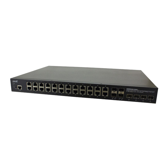
Page 21: Front Panels
Transition Networks SISPM1040-3xxx-L Install Guide Front Panels The SISPM1040-3248-L front panel is shown below: The SISPM1040-3166-L front panel is shown below: 33762 Rev. D https://www.transition.com Page 21 of 50... -
Page 22: Led Descriptions
Transition Networks SISPM1040-3xxx-L Install Guide LED Descriptions The LEDs on the front panel provide switch status checking and monitoring. There are three types of LEDs: System LED: Indicates if the switch is powered up correctly or not, or, indicates if there is a system alarm triggered for troubleshooting. -
Page 23: Reset Button
Transition Networks SISPM1040-3xxx-L Install Guide Port Status LEDs: Color Function Light off: port disconnected or link failed Green Light on: link-up (1G) TP Port Green/Amber Amber Light on: link-up (10/100M) Blinking: activity (receiving or transmitting data) Light off: port disconnected or link failed... -
Page 24: Back Panels
Transition Networks SISPM1040-3xxx-L Install Guide Back Panels The back panel of the -3166 and -3248 are shown below. AC Input: 100~ 250 VAC 50/60Hz: AC Input Voltage and Frequency: 100-250 VAC, 50~60 Hz DC INPUT 52-57 VDC (P1 and P2) and Ground Screw: DI/DO: Digital Input / Digital Output. -
Page 25: Manual Overview
Use a Web browser or the CLI to initially configure the switch, and • Troubleshoot the switch. Note that this manual provides links to third party web sites for which Transition Networks is not responsible. Related Manuals A printed Quick Start Guide is shipped with each device. -
Page 26: Chapter 2 - Installing The Switch
For 802.3at Environment B applications, i.e. building to building, copper to copper endpoint connections: 1) use an Ethernet network isolator module (PoE disabled), or 2) use mid-span injector(s), such as Transition Networks’ MIL-L100 or, L1000i-at, between this switch’s PSE port and link partner PD port. -
Page 27: Mounting The Switch In A 19-Inch Rack
Transition Networks SISPM1040-3xxx-L Install Guide Mounting the Switch in a 19-inch Rack 1. Attach the mounting brackets to both sides of the chassis. Insert screws and tighten with a screwdriver to secure the brackets. 2. Place the switch on a rack shelf in the rack. Push it in until the oval holes in the brackets align with the mounting holes in the rack posts. -
Page 28: Installing Sfp Modules
Transition Networks SISPM1040-3xxx-L Install Guide Installing SFP Modules You can install or remove a mini-GBIC SFP module from an SFP port without having to power off the switch. Note: The SFP ports should use UL Listed Optional Transceiver product, Rated 3.3Vdc, Laser Class 1. -
Page 29: Connecting The Ac Power Cord
Transition Networks SISPM1040-3xxx-L Install Guide Power Disconnection: To disconnect power from the switch after a successfully boot: 1. Turn off power to the switch. 2. Disconnect the cables. Connecting the AC Power Cord The SISPM1040-3xxx-L ships with one standard Power Supply installed. You can order one AC Power cord as a separate option. -
Page 30: Connecting The Dc Power Cord
Transition Networks SISPM1040-3xxx-L Install Guide Connecting the DC Power Cord The SISPM1040‐3248‐L/SISPM1040-3166-L has one AC power input and Dual DC power input. It doesn’t support a secondary AC Power Supply option. It provides redundancy between AC and dual DC power inputs and the AC power input has high priority. -
Page 31: Connecting The Di/Do Relay Wires
Transition Networks SISPM1040-3xxx-L Install Guide Connecting the DI/DO Relay Wires 1. Insert the negative (ground)/positive DI/DO Relay wires into the +/- terminals, respectively. 2. To keep the DI/DO Relay wires from pulling loose, use a small flat-blade screwdriver to tighten the wire- clamp screws on the front of the terminal block connector. - Page 32 Transition Networks SISPM1040-3xxx-L Install Guide Digital Input and Digital Output Use Case The switch supports Digital Input and Digital Output. The Digital Input enables the switch to detect and log external device status (such as door intrusion detector). The Digital Output could be used to tell administrators if the switch port shows link down, link up or power failure.
-
Page 33: Power Supply Specifications
Transition Networks SISPM1040-3xxx-L Install Guide Power Supply Specifications Power supply options include: • 25160 • 25104 • PS-DC-DUAL-56xxT Standalone Power Supply 25160 - 480W Din Rail Power Supply (SDR-480-48) TN Part number: 25160; see the 25160 webpage for product details. -
Page 34: Power Supply Views (25160)
Transition Networks SISPM1040-3xxx-L Install Guide Power Supply Views (25160) Front: Back: Top: Bottom: 33762 Rev. D https://www.transition.com Page 34 of 50... -
Page 35: Power Supply Dimensions (25160)
Transition Networks SISPM1040-3xxx-L Install Guide Power Supply Dimensions (25160) Width: 85.5 mm (3.36 in.) Height: 125.2 mm (4.92 in.) Depth: 128.5 mm (5.05 in.) ADMISSIBLE DIN-RAIL: TS35/7.5 OR TS35/15 33762 Rev. D https://www.transition.com Page 35 of 50... -
Page 36: Power Supply Pin Descriptions (25160)
Transition Networks SISPM1040-3xxx-L Install Guide Power Supply Pin Descriptions (25160) Terminal Pin No. Assignment (TB1) Pin No. Assignment AC/N AC/L Terminal Pin No. Assignment (TB2) Pin No. Assignment DC OUTPUT +V DC OUTPUT -V Relay Contact DC OK Relay Contact Contact Close PSU turns on / DC OK. -
Page 37: 25104 - Industrial Din Rail Mounted Power Supply
PS-DC-DUAL-56xxT 340W Standalone Power Supply Transition Networks PS‐DC‐DUAL‐56xxT Standalone Power Supplies are designed to provide power to the Transition Networks SISPM1040‐384‐LRT‐C. This standalone power supply can be installed in a 19” Rack with 1RU high. The Power Supply provides 340W at 56VDC and is targeted for PoE applications. -
Page 38: Chapter 3 - Initial Switch Configuration
Transition Networks SISPM1040-3xxx-L Install Guide Chapter 3 - Initial Switch Configuration Initial Switch Configuration via Web Browser After powering up the switch for the first time, you can perform the initial switch configuration using a web browser. For managing other switch features, see the Web User Guide for details. -
Page 39: Initial Switch Configuration Via Cli
Transition Networks SISPM1040-3xxx-L Install Guide If your PC is configured correctly, you will see the Login page of the switch as shown below. If you do not see the above login page, try these steps: Refresh the web page. Check to see if there is an IP conflict issue. -
Page 40: Chapter 4 - Troubleshooting
Transition Networks SISPM1040-3xxx-L Install Guide Chapter 4 - Troubleshooting Basic Troubleshooting 1. Make sure your switch model supports the feature or function attempted; see Key Features on page check the Release Notes for your particular firmware version. 2. Verify the install process; see Chapter 2 –... -
Page 41: Troubleshooting Table
Transition Networks SISPM1040-3xxx-L Install Guide Troubleshooting Table The following table provides information to help troubleshoot problems by taking actions based on the suggested solutions. Table 5: Troubleshooting Table Symptom Possible Cause Suggested Solution 1. Check if correct power cord is connected firmly to the switch and to the AC/DC outlet socket. -
Page 42: Led Troubleshooting
Transition Networks SISPM1040-3xxx-L Install Guide LED Troubleshooting Table 6: LED Troubleshooting Color State Description The port is enabled and established a link to connected device, and the Green connection speed is 1000Mbps. The port is transmitting/receiving packets, and the connection speed is... -
Page 43: Device Label And Packaging Label
Transition Networks SISPM1040-3xxx-L Install Guide Color State Description The port is enabled and established a link to connected device, and the Blue connection speed is 10Gbps. The port is transmitting/receiving packets, and the connection speed is Blue Blinking 10Gbps. The port is enabled and established a link to connected device, and the... -
Page 44: Record Device And System Information
After performing the troubleshooting steps, and before calling or emailing Technical Support, please record as much information as possible in order to help the Transition Networks Tech Support Specialist. 1. Select the Switch > System > System Information menu path. From the CLI, use the show commands needed to gather the information below or as requested by the TN Support Specialist. -
Page 45: Chapter 5 - Regulatory And Safety Information
Transition Networks SISPM1040-3xxx-L Install Guide Chapter 5 - Regulatory and Safety Information Compliance and Safety Statements FCC, Class A: This product has been tested and found to comply with the limits for a Class A digital device pursuant to Part 15 of the FCC Rules. These limits are designed to provide reasonable protection against harmful interference when the equipment is operated in a commercial environment. -
Page 46: Class I, Division 2 / Classe I, Division 2
Nuclear Facilities, Aircraft Navigation or Aircraft Communication Systems, Air Traffic Control, Life Support, or Weapons Systems ("High Risk Activities"). Transition Networks and its supplier(s) specifically disclaim any expressed or implied warranty of fitness for such High Risk Activities. -
Page 47: Electrical Safety Warnings
Transition Networks SISPM1040-3xxx-L Install Guide WARNING: A readily accessible, suitable National Electrical Code (NEC) or local electrical code approved disconnect device and branch-circuit protector must be part of the building's installed wiring to accommodate permanently connected equipment. Failure to observe this warning could result in an electric shock, even death. -
Page 48: Chapter 6 - Service, Warranty & Tech Support
In no event shall Transition Networks be liable for incidental or consequential damages, costs, or expenses arising out of or in connection with the performance of the product delivered hereunder. Transition Networks will in no case cover damages arising out of the product being used in a negligent fashion or manner. -
Page 49: Contact Us
Transition Networks reserves the right to charge a $50 fee for all testing and shipping incurred, if after testing, a return is classified as “No Problem Found.”... - Page 50 10900 Red Circle Drive Minnetonka, MN 55343 USA tel: +1.952.941.7600 | toll free: 1.800.526.9267 | fax: 952.941.2322 Copyright© 2018-2020 Transition Networks. All rights reserved. Printed in the U.S.A. SISPM1040-3xxx-L Rack Mount Industrial Ethernet Switch Install Guide, 33762 Rev. D 33762 Rev. D https://www.transition.com...
Need help?
Do you have a question about the SISPM1040-3 L Series and is the answer not in the manual?
Questions and answers