
Related Manuals for Kramer SID-X1


Summary of Contents for Kramer SID-X1
- Page 1 K R A ME R E LE CT R O N IC S L T D . USER MANUAL MODELS: SID-X1 Step-in Commander P/N: 2900-300754 Rev 5...
-
Page 3: Table Of Contents
Default EDID HDMI, DisplayPort and DVI PC-UXGA Figures Figure 1: SID-X1 Step-in Commander Front Panel Figure 2: SID-X1 Step-in Commander Rear Panel Figure 3: Connecting the SID-X1 Step-in Commander Figure 4: REMOTE STEP-IN Switch and LED Wiring Figure 5: REMOTE SELECT Switch and LED Wiring... -
Page 4: Introduction
Introduction Welcome to Kramer Electronics! Since 1981, Kramer Electronics has been providing a world of unique, creative, and affordable solutions to the vast range of problems that confront video, audio, presentation, and broadcasting professionals on a daily basis. In recent years, we have redesigned and upgraded most of our... -
Page 5: Getting Started
Do not secure the cables in tight bundles or roll the slack into tight coils • Avoid interference from neighboring electrical appliances that may adversely influence signal quality • Position your Kramer SID-X1 away from moisture, excessive sunlight and dust SID-X1 - Getting Started... -
Page 6: Shielded Twisted Pair/Unshielded Twisted Pair
Shielded Twisted Pair/Unshielded Twisted Pair Kramer engineers have developed special twisted pair cables to best match our digital twisted pair products; the Kramer BC-DGKat623 (CAT 6 23 AWG cable), and the Kramer BC-DGKat7a23 (CAT 7a 23 AWG cable). These specially built cables significantly outperform regular CAT 6 and CAT 7a cables. -
Page 7: Overview
Can be installed up to 50m (164ft) from the switcher • Features automatic live input detection when connected to a single input • Lockable EDID You can control the SID-X1 using the front panel buttons, or remotely via contact closure switches. SID-X1 - Overview... -
Page 8: Defining The Sid-X1 Step-In Commander
Press repeatedly to cycle and select one of the inputs to switch to the output STEP-IN Button Press to activate the input on the switcher that the SID-X1 is connected to ON LED Lights green when the device is powered on... -
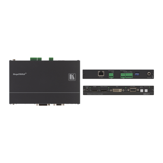
Page 9: Figure 2: Sid-X1 Step-In Commander Rear Panel
Figure 2 defines the rear panel of the SID-X1. Figure 2: SID-X1 Step-in Commander Rear Panel Feature Function TP OUT RJ-45 Connector Connect to a compatible switcher, for example, VP-81SID using CAT 6 or higher specification cable REMOTE STEP-IN 3-way... -
Page 10: Connecting The Sid-X1
Connecting the SID-X1 Switch off the power to all devices before connecting them to your SID-X1. After connecting your SID-X1 connect the power to other devices. Figure 3: Connecting the SID-X1 Step-in Commander To connect the SID-X1 and the as illustrated in Figure 1. -
Page 11: Connecting The Remote Step-In Switch And Led
LEDs (see Section 5.3). 7. Connect the power adapter to the SID-X1 and to the mains power. Note: All LED supplies include a current limiting resistor and are designed to work with any standard LED. Connecting the Remote Step-In Switch and LED... -
Page 12: Connecting The Remote Select Switch And Led
You can connect a remote, contact closure, input selection switch to activate an input (momentary contact is sufficient to switch inputs), as well as an indicator LED to the terminal block on the rear panel of the SID-X1. Figure 5 illustrates the connections from the terminal block to the switch and LED. -
Page 13: Connecting The Remote Input Selection Leds
Connecting the Remote Input Selection LEDs You can connect remote, input selection LEDS to the LED terminal block on the rear panel of the SID-X1 to indicate which is the active input. Figure 6 illustrates the connections from the terminal block to the LEDs. -
Page 14: Audio Mode Selection
Source Locking the EDID To prevent the stored EDID (either default or read from a device) from being overwritten, set DIP-switch 4 to ON. Note: The device must be power-cycled after you change DIP-switch 4. SID-X1 - Connecting the SID-X1... -
Page 15: Operating The Sid-X1
Taking Control of the Switcher Input To activate the input of the switcher to which the SID-X1 is connected, press the STEP-IN button. If the switcher grants the SID-X1 access to the input, the STEP- IN button lights. If the switcher does not grant access for some reason, the button flashes for a few seconds and then does not light. -
Page 16: Wiring The Twisted Pair Rj-45 Connectors
Brown Pair 1 4 and 5 Pair 2 1 and 2 Pair 3 3 and 6 Warning: Using a TP cable that is incorrectly wired will cause permanent damage to the device SID-X1 - Wiring the Twisted Pair RJ-45 Connectors... -
Page 17: Technical Specifications
18.8cm x 11.3cm x 2.5cm (7.4” x 4.5” x 1”) W, D, H rack-mountable WEIGHT: 0.48kg (1.1lbs) approx. ACCESSORIES: Power adapter OPTIONS: 19“ Rack adapter RK-T2B, RTBUS-12, RTBUS-22, SID-X1BP Kit (substitute black top plate for the SID-X1 to blend in with the color of the modular TBUS-10xl) SID-X1 - Technical Specifications... -
Page 18: Default Edid
Default EDID Each input on the SID-X1 is loaded with a factory default EDID. HDMI, DisplayPort and DVI Monitor Model name....SID-X1 Manufacturer..... KRM Plug and Play ID..KRM1200 Serial number.... 505-709990100 Manufacture date..2011, ISO week 255 ------------------------- EDID revision.... 1.3 Input signal type.. -
Page 19: Pc-Uxga
Screen size....520 x 320 mm (24.0 in) Power management..Standby, Suspend, Active off/sleep Extension blocs..None ------------------------- DDC/CI....n/a Color characteristics Default color space..sRGB Display gamma.... 2.20 Red chromaticity..Rx 0.674 - Ry 0.319 SID-X1 - Default EDID... - Page 20 CE vendor specific data (VSDB) IEEE registration number. 0x000C03 CEC physical address..1.1.0.0 Maximum TMDS clock..165MHz CE speaker allocation data Channel configuration..2.0 Front left/right..Yes Front LFE....No Front center..... No Rear left/right..No SID-X1 - Default EDID...
- Page 21 Rear center....No Front left/right center.. No Rear left/right center... No Rear LFE....No Raw data 00,FF,FF,FF,FF,FF,FF,00,2E,4D,00,12,01,01,01,01,FF,15,01,03,6E,34,20,78,EE,B3,25,AC,51,30,B4,26, 10,50,54,A5,4B,00,81,80,A9,40,71,4F,01,01,01,01,01,01,01,01,01,01,01,1D,00,72,51,D0,1E,20,6E,28, 55,00,07,44,21,00,00,1E,00,00,00,FF,00,35,30,35,2D,37,30,39,39,39,30,31,30,30,00,00,00,FC,00,53, 49,44,2D,4D,55,4C,54,49,00,00,00,00,00,00,00,FD,00,38,4C,1E,53,11,00,0A,20,20,20,20,20,20,00,A0, 02,03,1B,F1,48,10,05,84,03,02,07,16,01,23,09,07,07,65,03,0C,00,11,00,83,01,00,00,02,3A,80,18,71, 38,2D,40,58,2C,45,00,07,44,21,00,00,1E,01,1D,80,18,71,1C,16,20,58,2C,25,00,07,44,21,00,00,9E,01, 1D,00,72,51,D0,1E,20,6E,28,55,00,07,44,21,00,00,1E,8C,0A,D0,8A,20,E0,2D,10,10,3E,96,00,07,44,21, 00,00,18,00,00,00,00,00,00,00,00,00,00,00,00,00,00,00,00,00,00,00,00,00,00,00,00,00,00,00,00,46 SID-X1 - Default EDID...
- Page 23 For the latest information on our products and a list of Kramer distributors, visit our Web site where updates to this user manual may be found. We welcome your questions, comments, and feedback. Web site: www.kramerelectronics.com E-mail: info@kramerel.com SAFETY WARNING...
Need help?
Do you have a question about the SID-X1 and is the answer not in the manual?
Questions and answers