Table of Contents
Advertisement
Quick Links
Advertisement
Table of Contents

Related Manuals for Atmel SAM4E-EK


Summary of Contents for Atmel SAM4E-EK
- Page 1 SAM4E-EK User Guide SAM4E-EK Evaluation Kit 42067B−SAM4E−04/2013...
-
Page 2: Table Of Contents
ZigBee ……..................21 4.3.21 PIO expansion .................. 21 5. Configuration ..................23 PIO usage ....................... 23 Jumpers ......................26 6. Schematics ..................27 7. Revision History ................. 36 SAM4E-EK User Guide 42067B−SAM4E−04/2013... -
Page 3: Introduction
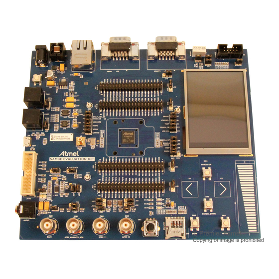
Introduction Scope This user guide introduces the SAM4E-EK Evaluation Kit (SAM4E-EK) and describes its development and debugging capabilities. Figure 1-1. Atmel SAM4E-EK board. User guide ® This guide gives details on how the Atmel SAM4E-EK has been designed. It is made up of six chapters: •... -
Page 4: Kit Contents
Kit Contents Deliverables The Atmel SAM4E-EK toolkit contains the following items: • An Atmel SAM4E-EK board • Power supply • Universal input AC/DC power supply with US, Europe and UK plug adapters • One USB cable • One serial RS232 cable •... -
Page 5: Electrostatic Warning
Electrostatic warning The Atmel SAM4E-EK board is shipped in a protective anti-static bag. The board must not be subjected to high electrostatic potentials. A grounding strap or similar protective device should be worn when handling the board. Avoid touching the components or any other metallic element of the board. -
Page 6: Power Up
Source code and technical support After boot up, you can run some sample code or your own application on the development kit. You can download sample code and get technical support from the Atmel web site: http://www.atmel.com. SAM4E-EK User Guide... -
Page 7: Board Description
Board Description Board overview This chapter introduces the Atmel SAM4E-EK Evaluation Kit design. It introduces system-level concepts, such as power distribution, memory, and interface assignments. ® The SAM4E-EK board is based on the integration of an ARM Cortex™-M4 processor with on-board NAND Flash and a set of popular peripherals. -
Page 8: Features List
BNC connector for ADC input • BNC connector for DAC output • User potentiometer connected to the ADC input • ® ZigBee connector • PIO connection interfaces (PIOA, PIOC and PIOD with 32-bit, PIOB with 16-bit, PIOE with 6-bit) SAM4E-EK User Guide 42067B−SAM4E−04/2013... -
Page 9: Function Blocks
The SAM4E16 features an External Bus Interface (EBI) that permits interfacing to a broad range of external memories and virtually to any parallel peripheral. The SAM4E-EK board is equipped with one NAND Flash MT29F2G08ABAEA on the EBI. This can change to other type of flash by setting the Static Memory Controller. -
Page 10: Clock Circuitry
Conversely, it can be asserted low from the outside to reset the microcontroller Core and the peripherals. The NRST pin integrates a permanent pull-up resistor of 100kΩ to VDDIO. On the SAM4E-EK board, the NRST signal is connected to the LCD module and JTAG port. Note: At power-on, the NRST signal is asserted with default duration of two clock cycles. -
Page 11: Power Supply And Management
Power supply and management The Atmel SAM4E-EK board is supplied with an external 5V DC block through input J1. It is protected by a PolyZen diode (MN2) and an LC combinatory filter (MN3). The PolyZen is used in the event of an incorrect power supply connection. -
Page 12: Uart
ADM3312EARU 4.7uF 100nF 100nF 100nF 100nF 100nF +3V3 100nF PA23 PA22 TXD1 T1IN T1OUT PA21_232 RXD1 R1OUT R1IN PA24 RTS1 T2IN T2OUT PA25 CTS1 R2OUT R2IN T3IN T3OUT +3V3 R3OUT R3IN PA21_485 FGND JP11 PA21 PA21_232 SAM4E-EK User Guide 42067B−SAM4E−04/2013... -
Page 13: Rs485
DMA interface. The Atmel SAM4E-EK is equipped with a MICREL KSZ8051MNL 10/100 Mbps Fast Ethernet Physical Layer transceiver. It contains the entire physical layer functions of 100BASE-TX as defined by IEEE 802.3u. -
Page 14: Can
CAN1 4.3.11 Display interface The SAM4E-EK carries a TFT transmissive LCD module with touch panel, FTM280C34D. Its integrated driver IC is ILI9325. The LCD display area is 2.8 inches diagonally measured, with a native resolution of 240 x 320 dots. -
Page 15: Backlight Control
On the anode drive line, a 0Ω resistor R18 is implemented in series for an optional current limitation. Figure 4-11. Backlight control. MN15 +3V3 AAT3155ITP-T1 PC13 EN/SET LED_A +3V3 OUTCP BN03K314S300R LED_K1 LED_K2 LED_K3 4.7uF LED_K4 LCD BACKLIGHT SAM4E-EK User Guide 42067B−SAM4E−04/2013... -
Page 16: Touch Screen Interface
AGND_TP 4.3.13 JTAG/ICE A standard 20-pin JTAG/ICE connector is implemented on the Atmel SAM4E-EK for the connection of a compatible ARM JTAG emulator interface, such as the SAM-ICE™ from Segger. Note that the NRST signal is connected to BP1 system button and is also used to reset the LCD module. The 0Ω... -
Page 17: Audio Interface
4.3.14 Audio Interface The Atmel SAM4E-EK evaluation kit supports mono/stereo audio driven by a TPA0223 audio amplifier connected to two DAC channels of the microcontroller. The TPA0223 is a 2W mono Bridge-Tied-Load (BTL) amplifier designed to drive speakers with as low as 4Ω... -
Page 18: Analog Interface
Each BNC input has an on-board 50Ω resistor termination that can be applied by closing jumper JP20, JP23 or JP26 • A 10kΩ potentiometer (VR1) is also connected to the AFE0_AD5 implement an easy access to ADC programming and debugging (or implement an analog user control like display brightness, volume, etc.) SAM4E-EK User Guide 42067B−SAM4E−04/2013... -
Page 19: Analog Output
JP21. A filter can be implemented on this output channel by replacing R74 and C69 with appropriate resistor and capacitor values, depending on the application requirements. Figure 4-18. DAC output. JP18 PB14 DAC1 2.2uF JP19 49.9R SAM4E-EK User Guide 42067B−SAM4E−04/2013... -
Page 20: Qtouch Elements
QTouch keys consist in a series of sensors formed by the association of a copper area and the capacitive effect of human fingers approaching it. Keys The Atmel SAM4E-EK implements two individual capacitive touch keys (RIGHT, LEFT). Slider A group of channels forms a Slider. A Slider is composed of eight channels for a QTouch acquisition method. Such a sensor is used to detect a linear finger displacement on a sensitive area. -
Page 21: Sd/Mmc Card
4.3.19 SD/MMC card The Atmel SAM4E-EK has a high-speed 4-bit multimedia MMC interface, which is connected to a 4-bit SD/MMC micro card slot featuring a card detection switch. Figure 4-21. SD card. +3V3 VDD_MCI SD POWER CTRL R161 SD CARD... - Page 22 PC29 PA13 PA29 PB13 PD14 PD30 PC14 PC30 PA14 PA30 PB14 PD15 PD31 PC15 PC31 PA15 PA31 +3V3 +3V3 +3V3 +3V3 +3V3 +3V3 +3V3 +3V3 PIO B & PIO E PIO A PIO D PIO C SAM4E-EK User Guide 42067B−SAM4E−04/2013...
-
Page 23: Configuration
Configuration This chapter describes the PIO usage, the jumpers, the test points and the solder drops of an Atmel SAM4E-EK board. PIO usage Table 5-1. PIO Port A pin assignments and signal descriptions. IO line Peripheral A Peripheral B Peripheral C... - Page 24 NCS1 PWML1 CANTX1 AFE0_AD7 CAN1_D PC16 A21/NANDALE NAND_ALE PC17 A22/NANDCLE NAND_CLE PC18 PWMH0 NAND_R/B# PC19 PWMH1 LCD_RS PC20 PWMH2 PC21 PWMH3 USB_VBUS PC22 PWML3 PC23 TIOA3 PC24 TIOB3 PC25 TCLK3 PC26 TIOA4 AFE0_AD12 PC27 TIOB4 AFE0_AD13 SAM4E-EK User Guide 42067B−SAM4E−04/2013...
- Page 25 PD28 ETH_INTR PD29 PD30 PD31 Table 5-5. PIO Port E pin assignments and signal descriptions. IO line Peripheral A Peripheral B Peripheral C Peripheral D Extra SYSIO Comments function and GPIO CAN0_Rs CAN0_EN CAN1_Rs CAN1_EN QTouch_CHANGE# SAM4E-EK User Guide 42067B−SAM4E−04/2013...
-
Page 26: Jumpers
Jumpers The Atmel SAM4E-EK board jumpers are essentially used for two main purposes: functional selection or current measurement. Details are given below. Table 5-6. 2 pin jumpers setting. Name Signal Close Open J37-1 SPI FLASH_CS (NPCS3) Connect (default) Disconnect J37-2... -
Page 27: Schematics
This chapter contains the following schematics: • Block diagram • Microcontroller • TFT-LCD and touch • COM and SD card and JTAG • Audio and USB • Ethernet • QTouch, CAN and Flash memories • I/O Peripheral SAM4E-EK User Guide 42067B−SAM4E−04/2013... - Page 28 Figure 6-1. Block diagram. SAM4E-EK User Guide 42067B−SAM4E−04/2013...
- Page 29 Figure 6-2. Microcontroller. SAM4E-EK User Guide 42067B−SAM4E−04/2013...
- Page 30 Figure 6-3. TFT-LCD and touch. SAM4E-EK User Guide 42067B−SAM4E−04/2013...
- Page 31 Figure 6-4. COM and SD card and JTAG. SAM4E-EK User Guide 42067B−SAM4E−04/2013...
- Page 32 Figure 6-5. Audio and USB. SAM4E-EK User Guide 42067B−SAM4E−04/2013...
- Page 33 Figure 6-6. Ethernet. SAM4E-EK User Guide 42067B−SAM4E−04/2013...
- Page 34 Figure 6-7. QTouch, CAN and Flash memories. SAM4E-EK User Guide 42067B−SAM4E−04/2013...
- Page 35 Figure 6-8. I/O Peripheral. SAM4E-EK User Guide 42067B−SAM4E−04/2013...
-
Page 36: Revision History
Revision History Doc. Rev. Date Comments 42067B 04/2013 A feature is added to the feature list in Chapter Some typos are fixed 42067A 01/2013 Initial document release. SAM4E-EK User Guide 42067B−SAM4E−04/2013... - Page 37 Disclaimer: The information in this document is provided in connection with Atmel products. No license, express or implied, by estoppel or otherwise, to any intellectual property right is granted by this document or in connection with the sale of Atmel products. EXCEPT AS SET FORTH IN THE ATMEL TERMS AND CONDITIONS OF SALES LOCATED ON THE ATMEL WEBSITE, ATMEL ASSUMES NO LIABILITY WHATSOEVER AND DISCLAIMS ANY EXPRESS, IMPLIED OR STATUTORY WARRANTY RELATING TO ITS PRODUCTS INCLUDING, BUT NOT LIMITED TO, THE IMPLIED WARRANTY OF MERCHANTABILITY, FITNESS FOR A PARTICULAR PURPOSE, OR NON-INFRINGEMENT.
- Page 38 Mouser Electronics Authorized Distributor Click to View Pricing, Inventory, Delivery & Lifecycle Information: Atmel ATSAM4E-EK...
Need help?
Do you have a question about the SAM4E-EK and is the answer not in the manual?
Questions and answers