Table of Contents
Advertisement
Advertisement
Table of Contents

Related Manuals for Brymen BM878


Summary of Contents for Brymen BM878
- Page 1 USER'S MANUAL BM878, BM877 & BM876 Insulation Tester Combination Multimeter...
- Page 2 1) SAFETY This manual contains information and warnings that must be followed for operating the instrument safely and maintaining the instrument in a safe operating condition. If the instrument is used in a manner not specified by the manufacturer, the protection provided by the instrument may be impaired.
-
Page 3: Cenelec Directives
The instrument is protected throughout by Double Insulation per IEC/UL/EN61010-1 Ed. 3.0, IEC/EN61010-2-030 Ed. 1.0, IEC/EN61010-2-033 Ed. 1.0, IEC/UL/EN61010- 031 Ed. 1.1 and CAN/CSA-C22.2 No. 61010-1-12 Ed. 3.0 to Measurement CAT-III 1kV and CAT-IV 600V, AC & DC. All input terminals are also rated to such Measurement Categories requirements. -
Page 4: Product Description
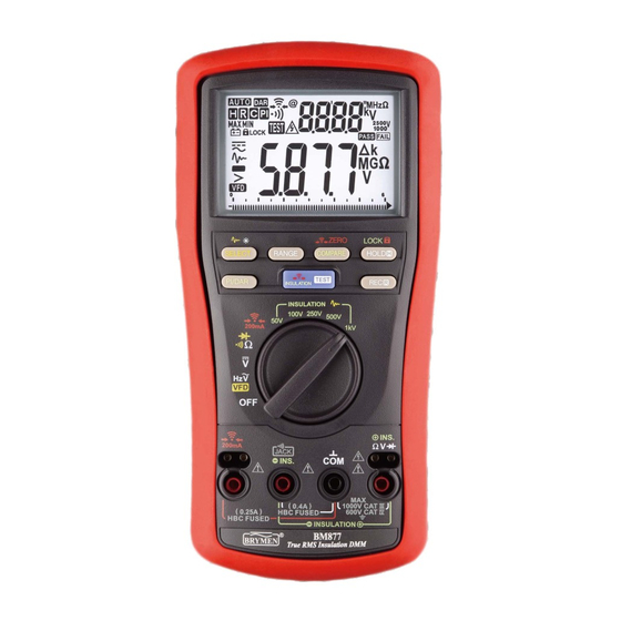
3) PRODUCT DESCRIPTION Note: Top of the line model is used as representative for illustration purposes. Please refer to your particular model for function availability. 1) 3-5/6 digits 6000 counts dual displays 2) Push-buttons for special functions & features 3) Selector to turn the Power On or Off and Select a function 4) Input Jack for... -
Page 5: Operation Caution
4) OPERATION CAUTION Before and after hazardous voltage measurements, test the voltage function on a known source such as line voltage to determine proper meter functioning. & VFD ACV functions Press the SELECT button momentarily to toggle the subject functions. Last selection will be saved as power up default for repeat measurement convenience. - Page 6 Resistance, Continuity functions Press the SELECT button momentarily to toggle the functions. Last selection will be saved as power up default for repeat measurement convenience. Continuity function is convenient for checking wiring connections and operation of switches. A continuous beep tone indicates a complete wire.
- Page 7 Diode Test, Capacitance (Model 878 only) functions Press the SELECT button momentarily to toggle the functions. Last selection will be saved as power up default for repeat measurement convenience. (Model 877 Diode Test function is combined to its / / Rotary Knob position) CAUTION Discharge capacitors before making any measurement.
- Page 8 DCmV, ACmV functions (Model 878 only) Press the SELECT button momentarily to toggle the subject functions. Last selection will be saved as power up default for repeat measurement convenience.
- Page 9 Temperature functions (Model 878 only) Press SELECT button momentarily to toggle C and F readings. Last selection will be saved as power up default for repeat measurement convenience. Note: Be sure to insert the banana plug type-K temperature bead probe Bkp60 with correct polarities.
- Page 10 Earth Continuity Test function (Models 878 & 877 only) WARNING This function measures the Resistance values of earth connection and equipotential bonding in Low Voltage Distribution Systems up to Nominal Voltage (U ) 830V, phase- to-phase. DO NOT use on Systems with Nominal Voltages above that. Measurements shall only be carried out on de-energized circuits.
- Page 11 range and 90mA for 21.99Ω range measurements, auto-ranging. Press the RANGE button momentarily to override auto-ranging and select a range. Press and hold for 1 second or more to resume auto-ranging. is active as long as the TEST button is pressed and hold. The TEST buttons on the meter and on the Remote Probe work alike.
- Page 12 ZERO mode is useful for offsetting measuring probes residue resistance reading in consecutive readings. Only residue readings from the 2.199Ω (200mA) range can be set as offset reference value. To apply, activate the Lock-Test as mentioned above. Connect the probes together to show the residue resistance reading and then press the ZERO button momentarily.
- Page 13 Insulation Resistance function WARNING The LCD icons used together throughout in this manual is referred as active measurements of Insulation Resistance function through the activation of the TEST button on the meter or on the Remote Probe. The sources a user selectable test voltage of 50V, 100V, 250V, 500V or 1000V to measure Insulation Resistance values.
- Page 14 is active as long as the TEST button is pressed and hold. The TEST buttons on the meter and on the Remote Probe work alike. The Insulation Resistance readings are shown on the primary display. Default startup primary display reading is “-.---”. Allow enough time for a good measuring result.
- Page 16 COMPARE mode (Models 877 & 876 only) This mode uses a preset insulation resistance threshold value for PASS/FAIL measuring comparison. The LCD annuciator turns on when the reading is higher than the selected threshold value. On the contrary, the LCD annuciator turns on and the meter chirps when the reading is below such value.
- Page 17 PI/DAR mode (Models 877 & 876 only) PI (Polarization Index) is the ratio of the 10-minute insulation resistance to the 1-minute insulation resistance. DAR (Dielectric Absorption Ratios) is the ratio of the 1-minute insulation resistance to the 30-second insulation resistance. A general guide to interpret the PI or DAR test results are: Insulation Condition PI (Polarization Index)
- Page 18 Then, activate Lock-Test mode & to start PI or DAR count-down measurements. The timer on the secondary display started to count down. The primary display shows the real-time resistance readings until the timer shows 00’00” for a result. The maximum display result is “5.0”, and the display shows “>5.0” for results beyond that.
- Page 19 Smooth mode (Insulation Resistance function only) Smooth mode displays the running average of the last eight measured readings having changes within 300 counts in sequence. On the contrary, it displays directly ,without smoothing, the measured reading that is beyond 300 counts in changes comparing to its former one.
-
Page 20: Maintenance Warning
Set Beeper Off Press the RANGE button while turning the meter on to temporarily disable the Beeper feature. Turn the rotary switch OFF and then back on to resume. Auto-Power-off (APO) The Auto-Power-off (APO) mode turns the meter off automatically to extend battery life after approximately 20 minutes of no rotary switch or push button operations. - Page 21 high impedance) like fuses to protect the user and the instrument. Most measuring functions through this terminal will then be open circuit. The series input protection resistors and the spark-gaps (or varistors) should then be replaced by qualified technician. Refer to the LIMITED WARRANTY section for obtaining warranty or repairing service.
-
Page 22: General Specification
GENERAL SPECIFICATION Display: 3-5/6 digits 6,000 counts Polarity: Automatic Update Rate: 5 per second nominal 61 Segments Bar graph: 40 per second max Operating Temperature: -10C to 40C Relative Humidity: Maximum relative humidity 90% for temperature up to 28C decreasing linearly to 50% relative humidity at 40C Pollution Degree: 2 IP Rating: IP40 Storage Temperature: -20C to 60C, <... - Page 23 110mA @20 Range 220mA @2.0 Range Tester can perform at least 3000 Earth Continuity Test measurements with new alkaline batteries at room temperature. These are standard tests of 1 with a duty cycle of 5 seconds on and 25 seconds off. Insulation Resistance @1mA test current: 50V output voltage: 25mA 100V output voltage: 45mA...
- Page 24 AC Voltage RANGE Accuracy 50Hz ~ 60Hz 6.000V, 60.00V, 600.0V, 1000V 1% + 3d 60Hz ~ 1kHz 6.000V, 60.00V, 600.0V, 1000V 2% + 3d 1kHz ~ 3kHz 6.000V, 60.00V 2% + 3d 600.0V, 1000V Unspecified 3kHz ~ 5kHz 6.000V, 60.00V 4% + 5d 600.0V, 1000V Unspecified...
- Page 25 Ohms RANGE Accuracy 0.9% + 5d 600.0 0.9% + 2d 6.000k, 60.00k, 600.0k 1.2% + 3d 6.000M 3.0% + 6d 60.00M Open Circuit Voltage: < 1.5VDC typical Audible Continuity Tester Audible threshold: between 20 and 200 Response time < 30ms Diode Tester Range Accuracy...
- Page 26 Temperature (Model 878 only) RANGE Accuracy -50.0C ~ 0.0C 2% + 3C 0.0C ~ 50.0C 2.2C 50.0C ~ 537.0C 2% + 2C -58.0F ~ 32.0F 2% + 6F 32.0F ~ 122.0F 4.4F 122.0F ~ 999.0F 2% + 4F Type-K thermocouple range & accuracy not included DCmA (Model 878 only) RANGE Accuracy...
- Page 27 ~ Hz Line Level Frequency Function RANGE Sensitivity (Sine RMS) Range 60mV 10Hz ~ 50kHz 600mV 60mV 10Hz ~ 100kHz 0.6V 10Hz ~ 20kHz 10Hz ~ 20kHz 600V 10Hz ~ 3kHz 1000V 600V 10Hz ~ 3kHz VFD 600V ~ 240V 10Hz ~ 440Hz 60mA 10Hz ~ 5kHz...
-
Page 28: Limited Warranty
BRYMEN's warranty does not apply to accessories, fuses, fusible resistors, spark gaps, varistors, batteries or any product which, in BRYMEN's opinion, has been misused, altered, neglected, or damaged by accident or abnormal conditions of operation or handling.
Need help?
Do you have a question about the BM878 and is the answer not in the manual?
Questions and answers