
Subscribe to Our Youtube Channel
Related Manuals for Brymen BM830 Series


Summary of Contents for Brymen BM830 Series
- Page 1 BRYMEN BM836, BM839 Mìøící a dílenské pøístroje / Multimetry USER'S MANUAL BRIGHT PEOPLE’S CHOICE Eshop: www.emareg.cz Email: shop@emareg.cz...
- Page 2 This manual contains information and warnings that must be followed for operating the meter safely and maintaining the meter in a safe operating condition. If the meter is used in a manner not specified by the manufacturer, the protection provided by the meter may be impaired. identifies conditions and actions that could result in serious injury or even death to the user. identifies conditions and acti ons that could cause damage or malfunction in the instrument. To reduce the risk of fire or electric shock, do not expose this product to rain or moisture. The meter is intended only for indoor use. Observe proper safety precautions when working with voltages above 33 Vrms, 46.7 Vpeak or 70 VDC. These voltage levels pose a potential shock hazard to the user. Before and after hazardous voltage measurements, check the voltage function on a known source such as line voltage to determine proper meter functioning. The meter meets UL/IEC/EN610101 Ed. 3.0, CAN/CSA C22.2 No. 61010 1 Ed. 3.0, UL/IEC/EN610102033 Ed. 1.0 to Measurement CATIII 1kV and CAT IV 600V, AC & The accompanied test probe assembly meets UL/IEC/EN61010 031 Ed. 1.1 to the same meter ratings or better. IEC 61010031 requires exposed conductive test probe tips ...
- Page 3 Disconnect the test leads from the test points before changing functions. Marking of Electrical and Electronic Equipment (EEE). Do not dispose of this product as unsorted municipal waste. Contact a qualified recycler Caution! Refer to the explanation in this Manual Caution! Possibility of electric shock Earth (Ground) Meter protected throughout by Double Insulation or Reinforced insulation Fuse Direct Current (DC) Alternating Current (AC) Threephase Alternating Current is applicable to test and measuring circuits connected at voltage MAINS installation. Examples are measurements on devices installed before the main fuse or circuit breaker in the building installation. is applicable to test and measuring circuits connected to voltage MAINS installation. Examples are measurements on distribu tion boards (including secondary meters), circuit breakers, wiring, including cables, bus bars, junction boxes, switches, socket outlets in the fixed installation, and equipment for industrial use and some other equipment such as stationary motors with permanent connection to the fixed installation. is applicable to test and measuring circuits connected directly to utilization points (socket outlets and similar points) of the low voltage MAINS installation. Examples are measurements on MAINS CIRCUITS of household appliances, portable tools and similar equipment.
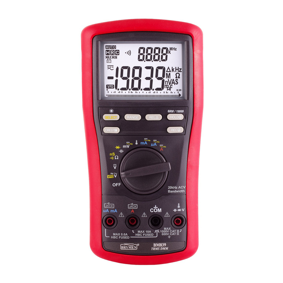
- Page 4 Note: Top of the line model is used as representative for illustration purposes. Please refer to your particular model for function availability. 1) 41/2 digits 20000 counts & 35/6 digits 6000 counts selectable dual displays 2) Pushbuttons for special functions & features 3) Selector to turn the Power On or Off and Select a function 4) Input Jack for mA/µA function positive input 5) Common (Ground reference) Input Jack for all functions 6) Input Jack for all functions EXCEPTA, mA and µA functions 7) Input Jack forA function positive input The analog bar graph provides a visual indication of measurement like a traditional...
- Page 5 Before and after hazardous voltage measurements, test the volta ge function on a known source such as line voltage to determine proper meter functioning. Press the button momentarily to toggle the subject functions. Last selection will be saved as power up default for repeat meas urement convenience. For function, press the button momentarily to select other ranges manually when needed. For function, default is set to 600V range to best cope with the measurements of most Variable Frequency Drives (VFD). Press the button momentarily to select1000V range when needed. Turn Rotary Knob to function position for measurements. Eshop: www.emareg.cz Email: shop@emareg.cz...
- Page 6 Press the button momentarily to select the subject functions. Last selection will be saved as power up default for repeat measurement convenience. function is having improved convenience for checking wiring connections and operation of switches. A continuous beep tone together with flashing display backlightindicate a complete wire. Such audible and visible indications improve continuity readabilities in noisy working environments. Conductance is the inverse of Resistance, that is S=1/ or nS=1/G . It virtually extends the Resistance measurements to the order of GigaOhms for leakage measurements. Using resistance, continuity or nS function in a live circuit will produce false results and may ...
- Page 7 When entering the range manually by button for high precision low resistance measurement, this feature will prompt you to short the inputs for temporary test lead resistance calibration on this range. The fastest way is to short the leads to auto range to the range, then press the button momentarily. The display sho Keep shorting the leads for further 3 seconds until the display shows zero . The lead resistance is then temporarily compensated. The compensation value stays until the next meter power reset, and can be as high as 5 . If you need a compensation value that is higher than that, Relative Zero mode is recommended.
- Page 8 Discharge capacitors before making any measurement. Large value capacitors should be discharged through an appropriate resistance load. Normal forward voltage drop (forwa rd biased) for a good silicon diode is between 0.400V to 0.900V. A reading higher than that indicates a leaky diode (defective). A zero reading indicates a shorted diode (defective). An OL indicates an open diode (defective). Reverse the test leads connect ions (reverse biased) across the diode. The digital display shows OL if the diode is good. Any other readings indicate the diode is resistive or shorted (defective). Eshop: www.emareg.cz Email: shop@emareg.cz...
- Page 9 Press the button momentarily to toggle the subject functions. Last selection will be saved as power up default for repeat measurement convenience. Eshop: www.emareg.cz Email: shop@emareg.cz...
- Page 10 Press button momentarily to toggle C and F readings. Last selection will be saved as power up default for repeat measurement convenience. Note: Be sure to insert the banana plug type K temperature bead probe Bkp60 with correct polarities. You can also use a plug adapter Bkb32 (Optional purchase) with banana pins to typeK socket to adapt other standard typeK mini plug temperature probes. Eshop: www.emareg.cz Email: shop@emareg.cz...
- Page 11 µ Press the button momentarily to toggle of the subject functions. Last selection will be saved as power up default for repeat measurement convenience. Press the button for 1 second or more to toggle the LCD backlight. The backlight will also be turned off automatically after approximate10 minutes to extend battery life. Press the button momentarily to select manual ranging, and the meter will remain in the range it was in, the LCD turns off. Press the button momentarily again to select an adjacent range. Press and hold the button for 1 second or more to resume autoranging. RelativeZero allows the user to offset the meter consecutive measurements with the main display displaying reading as the reference value. LCD turns on. Press the button momentarily to toggle RelativeZero mode. Eshop: www.emareg.cz Email: shop@emareg.cz...
- Page 12 The hold feature freezes the display for later view. LCD turns on. Press the button momentarily to toggle the hold feature. Press the button for one second or more to toggle between the Standard 6000 counts and 20000 counts High Resolution modes. The analog bar graph full scale shows accordingly. Last selectionis saved as power up default. 20000 counts High Resolution mode is available to AC/DC Voltage (except VFD ), AC/DC Current and Resistance functions. Press turn on. The meter beeps when a new MAX (maximum) or MIN (minimum) reading is updated. Press the button momentarily to read the Real time, MAX and MIN readings in sequence. Press the button for 1 second or more to exit MAX/MIN recording mode. When activated, AutoPowerOff is disabled automatically.
- Page 13 functions, especially voltage function, is selected. Press the button while turning the meter on to temporarily disable the Beeper feature. Turn the rotary switch OFF and then back on to resume. The AutoPoweroff (APO) mode turns the meter off automatically to extend battery life after approximately 20 minutes of no rotary switch or push button operations. To wake up the meter from APO, press the button momentarily or turn the rotary switch OFF and then back on. Always turn the rotary switch to the OFF positio n when the meter is not in use. Press the button while turning the meter on to temporarily disable the Auto PowerOff feature. Turn the rotary switch OFF and then back on to resume. To avoid electrical shock, disconnect the meter from any circuit, remove the test leads from the input jacks and turn OFF the meter before opening the case. Do not operate with open case. Install only the same type of fuse or equivalent Accuracy is specified for a period of one year after calibration. Periodic calibration at intervals of one year is recommended to maintain meter accuracy. Periodically wipe the meter and the test probe assembly with a damp cloth and mild detergent. Do not use abrasives or solvents. Allow to dry completely before operating. If the meter is not to be used for periods of longer than 60 days, remove the battery and store it separately If the instrument fails to operate, check battery, fuses, leads, etc., and replace as Refer to the LIMITED WARRANTY section for obtaining warranty or repairing service. Eshop: www.emareg.cz Email: shop@emareg.cz...
- Page 14 Four 1.5V AAalkaline batteries (IEC LR6) Fuse (F2) for input: 0.4A/1000Vac & Vdc, IR 30kA, F fuse; or better. Dimension: 6 x 32 mm Fuse (F3) forA input: 11A/1000Vac & Vdc, IR20kA, F fuse; or better. Dimension: 10 x 38 mm Loosen the screws from the access cover of the case bottom. Lift the access cover. Replace the batteries or fuse. Refasten the screws. Eshop: www.emareg.cz Email: shop@emareg.cz...
- Page 15 35/6 digits 6,000 counts &41/2 digits 20,000 counts max Automatic 5 per second nominal 5 per second nominal 40 per second max 10 C to50 C Maximum relative humidity 90% for temperature up to 28 C decreasing linearly to 50% relative humidity at50 C IP40 20 C to 60 C, < 80% R.H. (with battery removed) Operating below 2000m nominal 0.1 x (specified accuracy)/ C @(10 C ~ 18 C or 28 C ~50 C), or otherwise specified AC True RMS ETL certified per IEC/UL/EN610101 Ed. 3.0, IEC/UL/EN610102030 Ed. 1.0, IEC/UL/EN610102033 Ed. 1.0, IEC/UL/EN61010031 Ed. 1.1 and the corresponding CAN/CSAC22.2 regulations to MeasurementCategories: CAT III 1000 V AC & DC and Category IV 600V AC & DC µA &...
- Page 16 20 A typical L208mm X W103mm X H64.5mm with holster 635 gm with holster Test probe pair, Holster, User's manual, Bkp60 banana plug typeK thermocouple (Model 839 only) BKB32 banana plug to typeK socket plug adaptor (Model 839 only), BMH01 magnetic hanger; BMP86x soft carrying pouch VFD; Dual display +Hz Readings; Selectable 6,000 &20,000 Counts Resolution; HighUpdate Record MAX/MIN readings; Crest MAX/MIN readings; Relative Zero; Display Hold;LCD Backlight; BeepLit Continuity Tester, BeepJack audible & visible input warning Accuracy is (% reading digits + number of digits) or otherwise specified, at 23 5 C & less than 80% relative humidity. True RMS voltage & current accuracies are specified from 1% to 100 % of range or otherwise specified. Maximum Crest Factor < 1.
- Page 17 Add 20d @ reading >80% of range Unspecified forreadings < 5% of range Signal peak absolute values, includingDC bias, less than 1100mV peak 40Hz ~ 500Hz only for model 836 Model 839 Model 836 199.99mV , 1.9999V, 19.999V, 199.99V, 1000.0V 0.7% +30d 0.5% +30d 199.99mV , 1.9999V, 19.999V, 199.99V 1 % +30d 1000.0V 2 % +30d 199.99mV , 1.9999V, 19.999V, 199.99V 1.8% +40d 2% +40d 1000.0V Unspecified 199.99mV , 1.9999V, 19.999V, 199.99V 2% ...
- Page 18 Model 839 Model 836 600.0mV 0.09% +1d 0.18% +1d 6.000V, 60.00V 0.045% +1d 0.09% +1d 600.0V, 1000V 0.09% +1d 0.18% +1d Input impedance: 10M , 110pF nominal Model 839 Model 836 199.99mV 0.09% +6d 0.18% +6d 1.9999V, 19.999V, 199.99V 0.045% +6d 0.09% +6d 1000.0V 0.09% +6d 0.18% +6d Input impedance: 10M , ...
- Page 19 Model 839 Model 836 0.15% +20d 0.3% +20d 199.99 0.15% +6d 0.3% +6d 1.9999k , 19.999k 0.3% +6d 0.6% +6d 199.99k 0.5% +6d 0.7% +6d 1.9999M 1.5% +30d 2% +30d 19.999M Open Circuit Voltage:1.7VDC typical Specified with input lead resistance been offset by (short) feature Constant Test Current: 0.2 A Typical Constant Test Current: 0.02 A Typical Add 2% @ operation temperature >35 Continuity Threshold: Between 20 and 350 Response time: < 30ms...
- Page 20 40.0 C ~ 0.0 C 1% +2.0 C 0.0 C ~ 50.0 C 1% + 1.0 C 50.0 C ~1090.0 C 1% +1.5 C 40.0 F ~ 32.0 F 1% +3.6 F 32.0 F ~ 122.0 F 1% + 1.8 F 122.0 F ~1994.0 F 1% +2.7 F Accuracies assume meter interior has the same temperature of the ambient (isothermal stage) for a correct junction voltage compensation. Allow enough time to reach the isothermal stage for a significant change of ambient temperature. It can take up to an hour for changes > 5°C.
- Page 21 Model 839 Model 836 0.18% +40d 0.36% +40d 199.99 A 0.2mV/ A 0.18% +20d 0. 36% +20d 1999.9 A 0.2mV/ A 19.999mA 0.18% +40d 0. 36% +40d 3.0mV/mA 199.99mA 0.18% +30d 0. 36% +30d 3.0mV/mA 1.9999A 0.5% +40d 0.6% +40d 30mV/A 10.000A 0.7% ...
- Page 22 Model 839 Model 836 40Hz ~ 3kHz 199.99 A, 1999.9 A 0.2mV/ A 1% + 20d 1.2% + 20d 19.999mA, 199.99mA 3mV/mA 1.9999A, 10.000A 1% + 40d 1.2% + 40d 30mV/A 3kHz ~ 5kHz 199.99 A, 1999.9 A 0.2mV/ A 2% + 20d Unspecified 19.999mA, 199.99mA 3mV/mA 1.9999A, 10.000A Unspecified 30mV/A 10A continuous up to ambient 35 C; <15 mins on per >5 mins off @ 35 C ~ 50 >10A to 20A for <30 seconds on per >5 minsoff 199.99mV, 600.0mV 40mV 6Hz ~ 100kHz 1.9999V, 6.000V...
- Page 23 DC functions update interval100ms, nominal response to 85%; For changes > 200ms in duration: 6000count mode: Specified accuracy 12 counts 20000count mode: Specified accuracy 120 counts AC functions update interval 120ms,nominal response to 85%; For changes > 350ms in duration and input >5% of range: 6000count mode: Specified accuracy 30 counts 20000count mode:Specified accuracy 300 counts DC/AC functions For changes > 5ms in duration: 6000count mode only: Specified accuracy 150 counts Eshop: www.emareg.cz Email: shop@emareg.cz...
- Page 24 BRYMEN warrants to the original product purchaser that each product it manufactures will be free from defects in material and workmanship under normal use and service within a period of one year from the date of purchase. BRYMEN's warranty does not apply to accessories, fuses, fusible resistors, spark gaps, varistors, batteries or any product which, in BRYMEN's opinion, has been misused, altered, neglected, or damaged by accident or abnormal conditions of operation or handling. To obtain warranty service, contact your nearest BRYMEN authorized agent or send the product, with proof of purchase and description of the difficulty, postage and insurance prepaid, to BRYMEN TECHNOLOGY CORPORATION. BRYMEN assumes no risk for damage in transit. BRYMEN will, at its option, repair or replace the defective product free of charge. However, if BRYMEN deter mines that the failure was caused by misused, altered, neglected, or damaged by accident or abnormal conditions of operation or handling, you will be billed for the repair. THIS WARRANTY IS EXCLUSIVE AND IS IN LIEU OF ALL OTHER WARRANTIES, EXPRESSED OR IMPLIED, INCLUDING BUT NOT LIMITED TO ANY IMPLIED WARRANTY ...
Need help?
Do you have a question about the BM830 Series and is the answer not in the manual?
Questions and answers