
Subscribe to Our Youtube Channel
Related Manuals for MRC MH-4D


Summary of Contents for MRC MH-4D
- Page 1 Digital Hotplate With Stirrer MH-4D Operation Manual 3, Hagavish st. Israel 58817 Tel: 972 3 5595252, Fax: 972 3 5594529 mrclab...
- Page 2 MRC makes no representations or warranties with respect to this manual. In no event shall MRC be held liable for any damages, direct or incidental, arising out of or related to the use of this manual.
-
Page 3: Table Of Contents
Table of content Section 1 Warning and Cautions………….…..……………………………1-1 Section 2 General Description ………….………………..…………………2-1 Features Safety Convenience Construction Section 3 Unpacking and installation…………………….……….………3-1 Installation environment Connecting to Power Supply Location Condition Connecting to the main power Section 4 Operation……………………………………….…………………….4-1 Power On Change the Set Value (SV) Change the Alarm Value Autotuning (AT) -
Page 4: Warning And Cautions
After the smoke or odor disappears, contact your dealer or MRC if any repair is required. 3, Hagavish st. Israel 58817 Tel: 972 3 5595252, Fax: 972 3 5594529... - Page 5 Never disassemble, repair, or modify this equipment on your own. Doing so will void your warranty and may result in injuries or product damages. Do not heat any substances above temperature which will cause hazards of explosion, implosion or release of toxic or flammable gases from the material being heated.
- Page 6 Do not place heavy objects, including this equipment, on top of the power cord and do not strip, scratch, bend, twist, pull, or heat the power cord. A damaged power cord is a fire and electrical shock hazard. Make sure to set up this equipment on a flat, stable, clean, non-slip, dry, and fireproof surface inside a lab with proper safety measures.
- Page 7 Always disconnect from power supply prior to maintenance and servicing. Connect the instrument to a ground mains outlet, after ensuring that the Voltage is the same as given on the name plate The Instrument must be connected to an earthen (grounded) supply 3, Hagavish st.
-
Page 8: General Description
General Description Section 2 Congratulations of your purchase of MRC hotplate which is specially designed to provide maximum benefit for your investment with respect to performance, safety, ease of use, and durability. Item/Model MH-4D Dimension (W x D x H, mm) -
Page 9: Safety
Auto-tuning (AT) Automatic tuning of the PID parameters provides more accurate temperature control. Temperature Offsetting In case your own thermometer is to be used for temperature control for specific applications, there can be some differences between the temperature of your thermometer and the displayed temperature of this unit. -
Page 10: Construction
Construction (1) Top Plat (2) Radiation Sheets (3) Main Power Switch (4) FY-400 Temperature Controller (5) Stirring Control Knob (6) Stirring Switch (7) Stirring motor (8) Socket for Temperature Probe (9) Identification Label (10) Threaded Holes for Support Rod (Optional) (11) Power Cord 3, Hagavish st. -
Page 11: Unpacking And Installation
If such damage is found, notify the carrier immediately. After unpacking, check to ensure that all the following parts and accessories are included in the package. If not, contact your dealer or MRC immediately. Item Quantity Main Body... -
Page 12: Connecting To Power Supply
Location Conditions DANGER Never install or use this equipment in explosive atmospheres. Never install or use this equipment with or near to hazardous or flammable substances. Never expose this equipment to any heat sources including direct sunlight. ... -
Page 13: Connecting To The Main Power
Connecting to Main Power DANGER Check electrical requirements in the operation manual or on the ID plate attached to the back of this equipment before use. Make sure to connect this equipment only to properly grounded as well as dedicated power outlets to protect you and your equipment. -
Page 14: Operation
Operation Section 4 FY-401 Digital controller SYMBOL NAME FUNCTION Measured value Displays PV or various parameter symbols (PV) display (Red) Set value Displays SV or various parameter set values (SV) display (Green) Used for parameter calling up and set value Set key registration Auto/Manual key... -
Page 15: Power On
Operations Power On Controller will display as below Change the Set Value (SV) Change SV for example from 0 to 100 NOTICE You can change the temperature setting even during operation. Changing the temperature setting is allowed only within the low and high temperature limits. -
Page 16: Change The Alarm Value
Change the Alarm Value Change AL1 value for example to "5.0" (AL1 active, if PV exceeds SV over 5.0) Autotuning (AT) Temperature control using digital PID controllers have automatic auto-tune functions. During the auto-tune period the PID controller controls the power to the process and measures the rate of change, overshoot and response time of the plant. -
Page 17: Temperature Offsetting (Offset)
Temperature Offsetting (OFFSET) The temperature shown on the Actual Temperature Display is measured by a temperature sensor inside the unit. However, this temperature can be different from the temperature of your own thermometer which you may use as a standard for your specific applications. -
Page 18: External Temperature Probe Input (Optional)
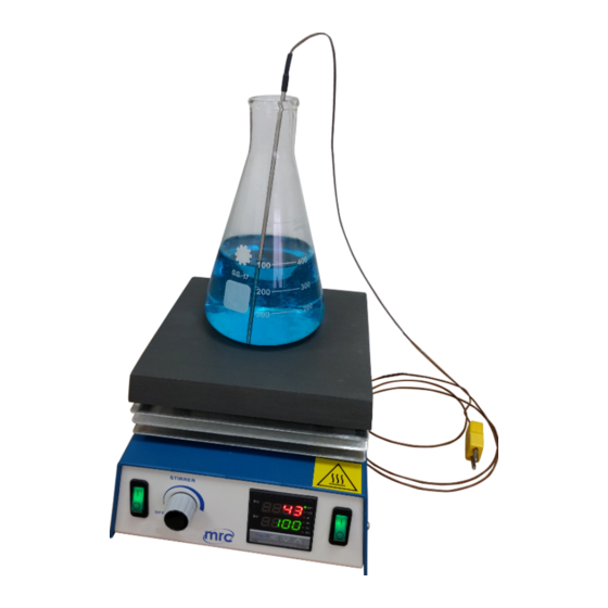
External Temperature Probe Input Connect the K type optional External Temperature probe into the back socket. To Connect the External Temperature Controller 1. Turn the Stir Control Knob and the main switch to the OFF position. 2. Disconnect power cord. 3. -
Page 19: Maintenance
Maintenance Section 5 Inspection Interval Item Daily Weekly Connection status of power cord or plug Damages in power cord or plug Cleanliness of top plate Cleanliness of main body and accessories Damages in plate, switches, buttons, Controller ... -
Page 20: Relocation
Cleaning Product (continued) Always make sure to keep top plate, main body, and accessories clean. Dirt and other foreign substances can cause fire or electric shock. Before attempting cleaning, (1) Disconnect the power cord from the power outlet and ensure that the equipment is cool enough, (2) Wipe with a soft dry cloth first to remove any foreign matter and, if not enough,... -
Page 21: Troubleshooting
Replace the damaged part with a Power outlets, plug, controller proper one. Internal circuit failure Contact MRC for service Disconnect all the appliances connected to the breaker first and reconnect them Electrical overload one by one to find the reason for the Repetitive tripping of overload. -
Page 22: Warranty Information
The Technical Services Department must give prior approval for return of any components or equipment. Your MRC Sales Office is ready to help with comprehensive site preparation information before your equipment arrives. Printed instruction manuals carefully detail equipment installation, operation and preventive maintenance.
Need help?
Do you have a question about the MH-4D and is the answer not in the manual?
Questions and answers