Advertisement
Quick Links
Download this manual
See also:
User Manual
Introduction
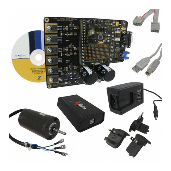
This quick start guide describes how to set up Zilog's Z8FMC16100 Series Motor Control
Development Kit and use it to evaluate your motor control designs and applications.
The Z8FMC16100 Series Motor Control Development Kit features a Motor Control Mod-
ular Development System (MC MDS) daughter board mounted on a 3-Phase Motor Con-
trol Application Board (see Figure 1). The MC MDS board consists of 32-LQFP
Z8FMC16100 chip and a DBG connector to connect the kit to a host development PC via
the USB Smart Cable. The 3-Phase Motor Control Application Board provides spade lug
connectors for the 3-phase motor and fused spade lug connectors for an adjustable 24 V
DC, 3 A workbench power source.
This document guides you through the following:
•
Power supply requirements to power the 3-phase motor supplied with the kit
•
How to run the kit's preloaded sample code in standalone mode
•
How to connect the kit to your development PC
•
Running the sample code in Zilog Developer System II (ZDS II) Debug mode
Kit Contents
All hardware (except an external adjustable power supply) software and documentation
required to evaluate the Zilog motor control solution is included within the Z8FMC16100
Series Motor Control Development Kit. For details about kit contents, refer to the
Z8FMC16100 Series Motor Control Development Kit Packing List (PAK0006). The sam-
ple code used in this development kit is based on the
trol with Z8 Encore! MC Microcontrollers Application Note
code
for this project (AN0226-SC01) can be downloaded at www.zilog.com.
System Requirements
Table 1 lists the system requirements for running ZDS II.
Z8 Encore! MC
Z8FMC16100 Series Motor
Control Development Kit
Quick Start Guide
®
Copyright ©2011 Zilog
www.zilog.com
™
Product Family
Sensorless Brushless DC Motor Con-
(AN0226). The
, Inc. All rights reserved.
QS005406-0111
latest sample
Advertisement

Subscribe to Our Youtube Channel
Related Manuals for ZiLOG Z8FMC16100 Series


Summary of Contents for ZiLOG Z8FMC16100 Series
- Page 1 QS005406-0111 Introduction This quick start guide describes how to set up Zilog’s Z8FMC16100 Series Motor Control Development Kit and use it to evaluate your motor control designs and applications. The Z8FMC16100 Series Motor Control Development Kit features a Motor Control Mod- ular Development System (MC MDS) daughter board mounted on a 3-Phase Motor Con- trol Application Board (see Figure 1).
-
Page 2: External Power Supply Requirements
3 A. The adjustable power supply leads must be fitted with spade lugs that connects to spade lugs (P4 and P5) on the 3-Phase Motor Control Application Board (see Figure 1). Running in Standalone Mode The Z8FMC16100 Series Motor Control Development Kit is shipped with the sample code from the application note AN0226 preloaded into the Z8FMC16100 chip’s internal... -
Page 3: Step 2. Set Switches And Jumpers
Z8FMC16100 Series Motor Control Development Kit Quick Start Guide Step 1. Connect the 3-Phase Motor to the Kit The 24 V DC 3-phase motor included with the kit features three spade connectors that plug into spade lugs P1, P2 and P3 on the 3-Phase Motor Control Application Board. Connect the motor leads to the spade lugs on the 3-Phase Motor Control Application Board as shown in Figure 2. - Page 4 Quick Start Guide • Speed Potentiometer R7 to its mid-point Refer to the Z8FMC16100 Series Motor Control Motor Control Development Kit User Manual (UM0192) for detailed jumper descriptions. Figure 2. Z8FMC16100 Series Motor Control Development Kit Motor and DBG Connections...
- Page 5 Z8FMC16100 Series Motor Control Development Kit Quick Start Guide Step 3. Configure the 5 V DC Universal Power Supply The universal power supply kit features different plug adapters in one box and the power supply in another. The power supply ships with a slide-out plate that must be removed to insert the location-specific plug adapter.
- Page 6 1. Stop the preloaded sample code and turn power to the 3-phase motor and MC MDS board off. 2. Install ZDS II – Z8FMC16100 Series Motor Control Series Software. 3. Install the USB Smart Cable driver software and USB Smart Cable.
- Page 7 Quick Start Guide Explorer, browse to your CD-ROM drive, and double-click the launch.exe file to launch the installer. b. DemoShield provides several installation options. Select Install Zilog Developer Studio to install now. You can install other software and accompanying documentation later.
- Page 8 Observe the following steps to install the USB Smart Cable for Windows XP systems. a. Connect the Zilog USB device to the Host PC. The Wizard Found New Hardware should activate automatically after connecting the Zilog USB device for the first ® time; Select if asked to connect to Windows Update.
- Page 9 Observe the following steps to install the USB Smart Cable for Windows 2000 systems. a. Connect the Zilog USB device to the Host PC. The Wizard Found New Hardware should activate automatically after connecting the Zilog USB device for the first time. b. Click in the Wizard after it has been activated.
- Page 10 Caution: the USB Smart Cable is connected both to the host PC and to the devel- opment board’s DBG port. c. Run the ZDS II software. By default, the Zilog Developer Studio II program is located in the menu under Start ...
- Page 11 IDE interface. Double-click the individual Project Files file to open the file in the ZDS II file editor. Figure 4. Zilog Developer Studio II Opening Screen The above figure is for reference only. You may have a newer version of Note: the software.
- Page 12 Z8FMC16100 Series Motor Control Development Kit Quick Start Guide g. Select the correct debug tool using ← ← ← Project Settings Debugger Debug . For example, Select when using the USB Smart Cable. Tool USBSmartCable Click for additional information about how to set up the debugger.
- Page 13 Use the Direction Switch S1 to change the direction in which the motor spins. Use Speed Potentiometer R7 to adjust the motor RPM. For more information about using Zilog Developer Studio II and building projects for your Z8FMC16100 Series Motor Control Development Kit, refer to the Zilog Developer Studio II –...
-
Page 14: Troubleshooting Tips
Try reloading the sample project as described in Executing Sample Code in Debug Mode using ZDS II on page 6. If you perform these steps and cannot get the sample code to run, contact Zilog Technical Support at www.zilog.com. QS005406-0111 Page 14 of 15... - Page 15 Z8, Z8 Encore!, Z8 Encore! XP, Z8 Encore! MC, Crimzon, eZ80, and ZNEO are trademarks or registered trademarks of Zilog, Inc. All other product or service names are the property of their respective owners.
Need help?
Do you have a question about the Z8FMC16100 Series and is the answer not in the manual?
Questions and answers