Sign In
Upload
Download
Table of Contents
Contents
Add to my manuals
Delete from my manuals
Share
URL of this page:
HTML Link:
Bookmark this page
Add
Manual will be automatically added to "My Manuals"
Print this page
×
Bookmark added
×
Added to my manuals
Manuals
Brands
Clarke Manuals
Power Tool
6505512
Operation & maintenance instructions manual
Clarke 6505512 Operation & Maintenance Instructions Manual
5-speed drill press
Hide thumbs
1
2
3
4
5
6
7
8
9
10
11
12
13
14
15
16
17
18
19
20
21
22
23
24
Table Of Contents
25
page
of
25
Go
/
25
Contents
Table of Contents
Troubleshooting
Bookmarks
Table of Contents
Environmental Protection
General Safety Rules
Electrical Connections
Head to Column
Settings and Adjustments
Trouble Shooting
Parts Diagram
Parts List
Declaration of Conformity
Advertisement
Quick Links
1
Parts Diagram
2
Parts List
Download this manual
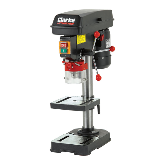
5-SPEED DRILL PRESS
MODEL NO: CDP102B
PART NO: 6505512
OPERATION & MAINTENANCE
INSTRUCTIONS
GC1115
Table of
Contents
Previous
Page
Next
Page
1
2
3
4
5
Advertisement
Table of Contents
Need help?
Do you have a question about the 6505512 and is the answer not in the manual?
Ask a question
Questions and answers
Related Manuals for Clarke 6505512
Power Tool Clarke BJ300 User Instructions
Biscuit jointer (17 pages)
Power Tool Clarke CDP152B Operation & Maintenance Instructions Manual
12-speed drill press (29 pages)
Power Tool Clarke COEBS1 Operation & Maintenance Instructions Manual
Oscillating belt/bobbin sander (25 pages)
Power Tool Clarke CBM 2 Operating & Maintenance Instructions
Mortising machine (14 pages)
Power Tool Clarke CBS43 Operation & Maintenance Instructions Manual
Drill bit sharpener (9 pages)
Power Tool Clarke Metalworker CDP202B Operation & Maintenance Instructions Manual
16-speed drill presses (29 pages)
Power Tool Clarke CJS380 Operating & Maintenance Instructions
(20 pages)
Power Tool Clarke METALWORKER CMPS1 Operation & Maintenance Instructions Manual
Multi purpose sharpener (17 pages)
Power Tool Clarke Metalworker CDP502F Operation & Maintenance Instructions Manual
12-speed drill press (29 pages)
Power Tool Clarke METALWORKER CBS20 Original Instructions Manual
Electric drill bit sharpener (17 pages)
Power Tool Clarke CDP5EB Operation & Maintenance Instructions Manual
(25 pages)
Power Tool Clarke CONTRACTOR CON 750 Operation & Maintenance Instructions Manual
(17 pages)
Power Tool Clarke Woodworker CBM1-C Operating & Maintenance Instructions
Bench mortiser (25 pages)
Power Tool Clarke CEW1000 Operating And Maintenance Instructions Manual
Electric impact wrench (20 pages)
Power Tool Clarke CMPS2 Operation & Maintenance Instructions Manual
Metalworker multi purpose sharpener (17 pages)
Power Tool Clarke METALWORKER CDP430VS Operation & Maintenance Instructions Manual
Variable speed digital (25 pages)
This manual is also suitable for:
Metalworker cdp102b
Table of Contents
Print
Rename the bookmark
Delete bookmark?
Delete from my manuals?
Login
Sign In
OR
Sign in with Facebook
Sign in with Google
Upload manual
Upload from disk
Upload from URL


Need help?
Do you have a question about the 6505512 and is the answer not in the manual?
Questions and answers