
Related Manuals for Clarke BJ300


Summary of Contents for Clarke BJ300
- Page 1 BISCUIT JOINTER BISCUIT JOINTER Model No: BJ300 Part No: 6462070 USER INSTRUCTIONS 0406...
-
Page 2: Table Of Contents
Please Note that details and specifications herein, are correct of time of going to print. However CLARKE International reserve the right to change specifications at any time without prior notice. Copyright CLARKE International All rights Reserved 2006. - 1 -... -
Page 3: General Safety Precautions
GENERAL SAFETY PRECAUTIONS WARNING: PLEASE READ ALL INSTRUCTIONS CAREFULLY BEFORE OPERATING As with all machinery, there are certain hazards involved with their operation and use. Exercising respect and caution will considerably lessen the risk of personal injury. However, if normal safety precautions are overlooked or ignored, personal injury to the operator or damage to property, may result. -
Page 4: Additional Safety Precautions For Power Tools
GENERAL SAFETY PRECAUTIONS CONTINUED • ALWAYS keep your proper footing and balance at all times DO NOT over reach. For best footing wear rubber soled footwear. Keep floor clear of oil, scrap wood etc. • ALWAYS use recommended accessories, the use of improper accessories could be hazardous. -
Page 5: Additional Safety Precautions For Biscuit Jointers
• DO NOT use high speed steel (HSS) blades or blades that are deformed or cracked etc. Replacement blades are available from your CLARKE dealer. ELECTRICAL CONNECTIONS This product is provided with a standard 13 amp, 230 volt (50Hz) BS1363 plug, for connection to a standard, domestic electrical supply. -
Page 6: Technical Specification
TECHNICAL SPECIFICATION Description: Model No: ....................BJ300 Part No: ....................6462070 Product use: ................ DIY/Light Industrial Product Specification: Typical Application: ..............Wood Joining No Load Speed: ................11,000 RPM IP Rating: ......................20 Fence Adjustment: ................0°-135° Cutting Depth Preset Modes: 0: .............. 8mm 10: ............ -
Page 7: Parts Description
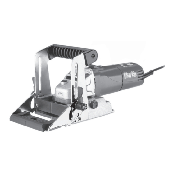
PARTS DESCRIPTION Handle Fence Bevel Adjustment Lever Sight Depth Adjustment Knob Window Kerf Guide Spindle Lock Lock ‘ON’ Switch Base Dust Extraction Port Fig.1 SETUP ADJUSTING THE CUTTING DEPTH ALWAYS Switch the tool OFF and unplug from the power supply BEFORE making any adjustments. - Page 8 SETUP CONTINUED ADJUSTING THE CUTTING HEIGHT NOTE: Always unplug the biscuit jointer before making any adjustments. • The height can be set by unlocking both of the bevel adjustment levers and sliding the fence to the desired level with the aid of the scale. (refer to fig.1).
-
Page 9: Operation
OPERATION MAKING EDGE TO EDGE JOINTS NOTE: Always unplug the biscuit jointer before making any adjustments. Draw a reference mark ‘A’ at 90° to the centre point of each proposed joint location ‘B’, space additional joints along the timbers edge approx. 100mm apart. - Page 10 OPERATION CONTINUED MAKING MITRE JOINTS NOTE: Always unplug the biscuit jointer before making any adjustments. Using a combination square draw a reference mark ‘A’ through the centre point of each joint perpendicular to the mitred edge ‘B’. Follow the cutting instructions (2-14) for edge to edge jointing on page 8.
- Page 11 OPERATION CONTINUED MAKING ‘T’ JOINTS NOTE: Always unplug the biscuit jointer before making any adjustments. A ‘T’ joint is used when the end of one piece is joined to the face of another, a typical application would be connecting the shelves of a bookcase to the vertical supports.
-
Page 12: Blade Replacement
BLADE REPLACEMENT ALWAYS switch off and isolate from the mains supply by removing the plug from the mains socket BEFORE changing the blade. Remove the kerf guide by unscrewing the two screws with a cross head screwdriver. (circled in fig.3). Place the biscuit jointer upside down on a workbench. -
Page 13: Parts List
PARTS LIST - 12 -... - Page 14 PARTS LIST ITEM: DESCRIPTION: PART NO: ITEM: DESCRIPTION: PART NO: Rubber bearing shoe ..HT30001 Spring washer ....HT30040 Bearing ....... HT30002 Nut ........HT30041 Armature ......HT30003 Screw ........HT30042 Check ring ......HT30004 Slide switch knob ....HT30043 Bearing cap .......
-
Page 15: Maintenance
Do not use for heavy duty work, do Tool is being overloaded. not apply excessive pressure. PROBLEM: Excessive Sparking Occurs. CAUSE: TROUBLE SHOOTING: Consult your CLARKE dealer for parts Worn motor brushes. and advise. PROBLEM: Biscuit Jointer does not operate when switched ON. CAUSE: TROUBLE SHOOTING: Check the fuse is sound and replace Blown fuse. -
Page 16: Hand Arm Vibration Explanation
HAND-ARM VIBRATION Employers are advised to refer to the HSE publication “Guide for Employers”. All hand held power tools vibrate to some extent, and this vibration is transmitted to the operator via the handle, or hand used to steady the tool. Vibration from about 2 to 1500 herz is potentially damaging and is most hazardous in the range from about 5 to 20 herz. -
Page 17: Declaration Of Conformity
- 16 -...
Need help?
Do you have a question about the BJ300 and is the answer not in the manual?
Questions and answers