
Subscribe to Our Youtube Channel
Related Manuals for Clarke Metalworker CDP202B


Summary of Contents for Clarke Metalworker CDP202B
- Page 1 16-SPEED DRILL PRESSES MODEL NO: CDP202B, 302B, 352F, 452B & 452F PART NO: 6505532, 6505552, 6505562, 6505575 & 6505582 OPERATION & MAINTENANCE INSTRUCTIONS GC1216...
-
Page 2: Environmental Protection
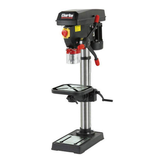
INTRODUCTION Thank you for purchasing this CLARKE Drill Press. Before attempting to use this product, please read this manual thoroughly and follow the instructions carefully. In doing so you will ensure the safety of yourself and that of others around you, and you can look forward to your purchase giving you long and satisfactory service. -
Page 3: General Safety Rules
2. Always keep guards in place and in working order. A guard or other part that is damaged should be properly repaired or replaced by your Clarke service department, unless otherwise indicated in this instruction manual. -
Page 4: Additional Safety Rules For Drill Presses
Check for alignment of moving parts, binding of moving parts, breakage of parts, mounting or other condition that may affect its operation. 7. Have defective switches repaired by your Clarke Service Dept. Do not use a power tool if the switch does not turn it on and off. -
Page 5: Protective Clothing
3. Always use clamps or a drill vice bolted to the table, to hold the work. It should never be held with bare hands. 4. Always shut off the power before leaving the drill press. 5. Always make all adjustments with the power off. 6. -
Page 6: Safety Symbols
SAFETY SYMBOLS The following symbols are shown on the product or it’s packaging. Read instruction CE Mark manual before use Do not wear gloves Falls within Waste Electrical Equipment (WEEE) Directive Wear eye protection Parts & Service: 020 8988 7400 / E-mail: Parts@clarkeinternational.com or Service@clarkeinternational.com... -
Page 7: Electrical Connections
ELECTRICAL CONNECTIONS WARNING! READ THESE ELECTRICAL SAFETY INSTRUCTIONS THOROUGHLY BEFORE CONNECTING THE PRODUCT TO THE MAINS SUPPLY. Before switching the product on, make sure that the voltage of your electricity supply is the same as that indicated on the rating plate. This product is designed to operate on 230VAC 50Hz. -
Page 8: Parts Inventory
PARTS INVENTORY Feed Handle Assembly Chuck Guard Assembly Head & Motor Assembly Chuck with key Table Elevating Crank Handle Base Casting (bench mounting style shown) Rack Securing Collar Bolts & washer kit Column Hex Keys (3, 4 & 6mm) Table Elevating Rack Drift Wedge Table with Support Bracket (wet T-slot style shown) -
Page 9: Column To Base
The drill press is delivered with the components shown on page 8. Check the parts against the list. Should there be any deficiencies or damage, you should contact your CLARKE dealer immediately where the product was originally purchased. Do not discard the packaging until the drill press is assembled. The packaging consists of cardboard and appropriately marked materials which can be sent to a re-cycling facility. - Page 10 TABLE TO COLUMN 1. Push the crank onto the worm drive spigot protruding from the gear housing. Tighten the crank set screw onto the flat side of the spigot using a hex key supplied. 2. Position the rack in the slot in the table support, so that the rack teeth engage with the worm gear.
-
Page 11: Head To Column
7. Ensure there is sufficient clearance to allow the complete table assembly to move around the column. If necessary, reposition the collar to achieve good movement. 8. Check that the table moves smoothly from top to bottom of the rack by turning the crank handle. -
Page 12: Chuck Guard Assembly
2. Tap the chuck firmly with a rubber mallet until the tapered end of the chuck engages with the drive spindle. CAUTION: IF A RUBBER MALLET IS NOT AVAILABLE, PROTECT THE CHUCK WITH A BLOCK OF SCRAP TIMBER BEFORE STRIKING WITH A HAMMER. ALWAYS ENSURE THE CHUCK JAWS ARE FULLY OPEN BEFORE STRIKING THE CHUCK. -
Page 13: Checking The Operation Of The Microswitch
NOTE: If the belt slips whilst drilling, increase the belt tension. CHECKING THE OPERATION OF THE MICROSWITCH When closing the cover, check the operation of the micro-switch. It is important that it operates as soon as the cover is opened in order to prevent the drill press from operating whilst the cover is open. -
Page 14: Spindle Depth Stop
large drill bit in the chuck, place a set-square on the table, and bring it up to the drill. Adjust the table if necessary, so that it is perfectly level. SPINDLE DEPTH STOP Located on the spindle feed shaft is a depth stop collar, displaying a graduated scale (A, in Fig.15). -
Page 15: Drill Operating Speeds
3. When the belt has been correctly positioned, re-tension by levering the motor away from the head until the belt deflects by approx 10 mm at its centre when using reasonable thumb pressure. Lock the motor in this position with the belt tension locking screws. DRILL OPERATING SPEEDS The table below gives the belt arrangement for given drilling speeds. -
Page 16: Operation
OPERATION 1. Insert the drill bit into the jaws of the chuck by approx 1", ensuring that the jaws do not touch the flutes of the drill bit. Before tightening the chuck, ensure that the drill bit is correctly centred. 2. - Page 17 8. When completely satisfied that the setup is correct, lower the chuck guard into position and switch the drill press on by pushing the ‘I’ button. To switch off, push the ‘O’ button, see Fig 18. 9. During use, the emergency stop button will drop down over the other buttons.
-
Page 18: Drilling Speeds
12.5 Steel DRILL VICES In order to secure the workpiece to the table, a complete range of drill vices, cross vices and clamps is available from your Clarke dealer. Parts & Service: 020 8988 7400 / E-mail: Parts@clarkeinternational.com or Service@clarkeinternational.com... -
Page 19: Maintenance
Always unplug from the power supply before carrying out any adjustment, servicing or maintenance. Please refer to the Troubleshooting chart on page 20. If you are unable to rectify any faults, please contact your local dealer or Clarke International for assistance. MONTHLY (IF IN CONSTANT USE) 1. -
Page 20: Troubleshooting
Close pulley cover. g. Micro switch on cover g. Check operation of micro not operating. switch, and renew/adjust as necessary. (Consult your Clarke dealer for advice). Drill binds in work- a. Excessive feed a. Apply less pressure. piece. pressure. - Page 21 Drill bit burns or a. Incorrect speed. a. Refer to Cutting Speed chart smokes. & adjust drill speed accordingly. b. Swarf is not discharging b. Clean drill. c. Dull drill or not proper c. Check sharpness & taper. clearance for material. d.
-
Page 22: Suitable Accessories
SUITABLE ACCESSORIES Drill Press Vices available from your Clarke dealer include: Model Jaw Width Max Opening Depth Weight Part No CDV30C 76 mm 78 mm 19 mm 2 kg 6504019 CDV40C 102 mm 97 mm 28 mm 3 kg 6504020... -
Page 23: Specification
SPECIFICATION Model CDP202B CDP302B CDP352F CDP452B CDP452F Part Number 6505532 6505552 6505562 6505575 6505582 Mounting Style Bench Bench Floor Bench Floor Product Weight (kgs) Overall Height 970 mm 1560mm 990mm 1560mm Table Dimensions (mm) 248 x 248 290 dia 290 dia 290x290 288x288 Base Dimensions (mm) -
Page 24: Component Parts
COMPONENT PARTS Parts & Service: 020 8988 7400 / E-mail: Parts@clarkeinternational.com or Service@clarkeinternational.com... - Page 25 COMPONENT PARTS No Description No Description Base (floor or bench mounting) Slip Shaft Column Flange Adjusting Shaft Spring Washer Flat Washer Hex Bolt M8x25 Hex Bolt M8x25 Rack Flat Washer Column (state short or tall) Motor Connection Plate Cross Pan Head Screw Nut M12 Rack Collar Hex Socket Head Screw...
- Page 26 Belt 0-565 Cross Head ST Screw M5x12 Spindle Pulley Crank Circlip 40mm Hex Socket Head Screw M6x8 Keyway Spindle Circlip 14mm Bearing Worm Drive Hex Wrench S4 Worm Gear Hex Wrench S6 Table Support Drift Wedge (chuck removal) Worm Pin Cross Head Screw M5x16 Angle Label Cable Clamp...
-
Page 27: Declaration Of Conformity
DECLARATION OF CONFORMITY Parts & Service: 020 8988 7400 / E-mail: Parts@clarkeinternational.com or Service@clarkeinternational.com...
Need help?
Do you have a question about the Metalworker CDP202B and is the answer not in the manual?
Questions and answers