Sign In
Upload
Download
Table of Contents
Contents
Add to my manuals
Delete from my manuals
Share
URL of this page:
HTML Link:
Bookmark this page
Add
Manual will be automatically added to "My Manuals"
Print this page
×
Bookmark added
×
Added to my manuals
Manuals
Brands
Clarke Manuals
Power Tool
CDP5EB
Operation & maintenance instructions manual
Clarke CDP5EB Operation & Maintenance Instructions Manual
Hide thumbs
1
2
3
4
5
6
7
8
9
10
11
12
13
14
15
16
17
18
19
20
21
22
23
24
Table Of Contents
25
page
of
25
Go
/
25
Contents
Table of Contents
Troubleshooting
Bookmarks
Table of Contents
General Safety Rules
General Safety in the Workplace
Care of Power Tools
Protective Clothing
Electrical Connections
Product Overview
Column to Base
Head to Column
Chuck Guard Assembly
Assembling the Depth Stop
Installing the Chuck
Tensioning the Drive Belt
Settings and Adjustments
Spindle Depth Stop
Changing Drill (Spindle) Speed
Drill Speed Table
Operation
Cutting Speeds
Maintenance
Environmental Protection
Troubleshooting
Suitable Accessories
Specification
Parts Diagram
Parts List
Declaration of Conformity
Advertisement
Quick Links
Download this manual
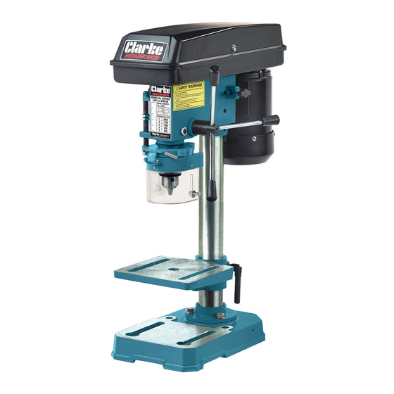
DRILL PRESS
MODEL NO: CDP5EB/RB
PART NO: 655030 & 655035
OPERATION & MAINTENANCE
INSTRUCTIONS
GC0513
Table of
Contents
Previous
Page
Next
Page
1
2
3
4
5
Advertisement
Table of Contents
Need help?
Do you have a question about the CDP5EB and is the answer not in the manual?
Ask a question
Questions and answers
Related Manuals for Clarke CDP5EB
Power Tool Clarke Metalworker CDP501F Operating & Maintenance Manual
20mm drill press (23 pages)
Power Tool Clarke METALWAORKER CDP502F Operation & Maintenance Instructions Manual
12-speed drill press (29 pages)
Power Tool Clarke CDP5RB Operation & Maintenance Instructions Manual
(25 pages)
Power Tool Clarke Metalworker CDP101B Operating & Maintenance Manual
13mm drill press (19 pages)
Power Tool Clarke MetalWorker CDP151B Operating & Maintenance Manual
13mm drill press (19 pages)
Power Tool Clarke Metalworker CDP301B Operating & Maintenance Manual
16mm (21 pages)
Power Tool Clarke METALWORKER CDP201B Operating And Maintenance Instructions Manual
13mm drill press (21 pages)
Power Tool Clarke CDP10B Operation & Maintenance Instructions Manual
(29 pages)
Power Tool Clarke METALWORKER CDP10B Operating & Maintenance Instructions
12 speed drill press (19 pages)
Power Tool Clarke CDP152B Operation & Maintenance Instructions Manual
12-speed drill press (29 pages)
Power Tool Clarke Metalworker CDP102B Operation & Maintenance Instructions Manual
5-speed drill press (25 pages)
Power Tool Clarke METALWORKER CDP401B Operating & Maintenance Instructions
16mm (32 pages)
Power Tool Clarke METALWORKER CDP451F Operating & Maintenance Instructions
16mm (32 pages)
Power Tool Clarke Metalworker CDP202B Operation & Maintenance Instructions Manual
16-speed drill presses (29 pages)
Power Tool Clarke METALWORKER CDP430VS Operation & Maintenance Instructions Manual
Variable speed digital (25 pages)
Power Tool Clarke METALWORKER CDP425RA Operation & Maintenance Instructions Manual
Radial arm (29 pages)
This manual is also suitable for:
Cdp5rb
655030
655035
Table of Contents
Print
Rename the bookmark
Delete bookmark?
Delete from my manuals?
Login
Sign In
OR
Sign in with Facebook
Sign in with Google
Upload manual
Upload from disk
Upload from URL


Need help?
Do you have a question about the CDP5EB and is the answer not in the manual?
Questions and answers