
Subscribe to Our Youtube Channel
Related Manuals for AXIOMTEK MPC103-845


Summary of Contents for AXIOMTEK MPC103-845
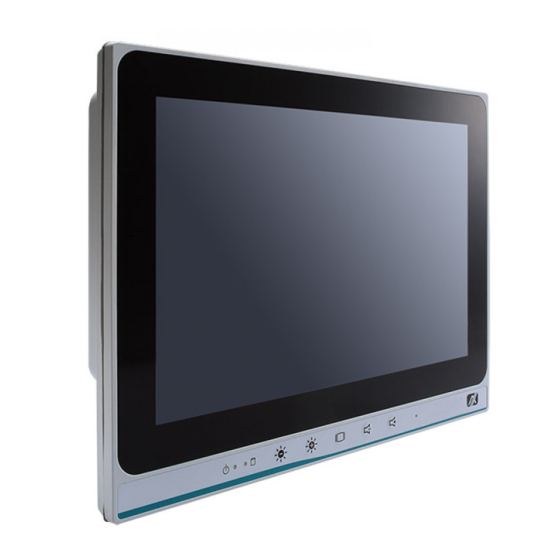
- Page 1 MPC103-845 All-in-One 10.1” WXGA TFT Fanless Touch Panel Computer with Intel® Celeron® Processor N3060 onboard User’s Manual...
- Page 2 Axiomtek does not make any commitment to update the information in this manual. Axiomtek reserves the right to change or revise this document and/or product at any time without notice. No part of this document may be reproduced, stored in a retrieval system, or transmitted, in any form or by any means, electronic, mechanical, photocopying, recording, or otherwise, without the prior written permission of Axiomtek Co., Ltd.
-
Page 3: Safety Precautions
Most electronic components are sensitive to static electrical charge. Disconnect the power cords from the MPC103-845 Series before making any installation. Be sure both the system and the external devices are turned OFF. Sudden surge of power could ruin sensitive components. Make sure the MPC103-845 Series is properly grounded. -
Page 4: Table Of Contents
Table of Contents Disclaimers ..................... ii Safety Precautions ..................iii Chapter 1 Introduction ..........1 General Description ................1 Specifications ..................2 1.2.1 Main CPU Board ..................2 1.2.2 I/O System ....................2 1.2.3 System Specifications ................. 3 Dimensions ..................4 I/O Outlets .................... - Page 5 3.3.2 Hardware Monitor ..................32 3.3.3 ACPI Settings .................... 33 3.3.4 CPU Configuration ..................34 3.3.5 SATA Configuration ................... 35 3.3.6 USB Configuration..................36 3.3.7 Utility Configuration ................... 36 3.3.8 PCIE/mSATA Mini Card Configuration ............37 Chipset Menu ..................38 3.4.1 North Bridge ....................
- Page 6 This page is intentionally left blank.
-
Page 7: Chapter 1 Introduction
Windows 8.x, Windows 10 and Windows embedded OS. This panel computer can house an mSATA for storage and two Mini card slots for wireless connection. Its excellent ID and friendly user interface make it a professional yet easy-to-use panel computer. The MPC103-845 is an ideal for space-limited in medical application. -
Page 8: Specifications
One Mini-card slot (mSATA supported as an option) Storage One mSATA One half slim SSD Power connector MPC103-845-J: 12 VDC with external 65W AC adapter and screw type connector; MPC103-845-DC : 9~36 VDC with phoenix power connector Introduction... -
Page 9: System Specifications
Power output: 12 VDC, Max. 5.42 A — NOTE All specifications and images are subject to change without notice. NOTE The DC power source to be used with MPC103-845 must be galvanically isolated according to IEC60601-1 safety of medical devices! Introduction... -
Page 10: Dimensions
MPC103-845 User’s Manual Dimensions This diagram shows you dimensions and outlines of the MPC103-845. Introduction... -
Page 11: I/O Outlets
MPC103-845 User’s Manual I/O Outlets Please refer to Figures 1-1 and Table 1-1 for I/O locations at the bottom of the MPC103-845. Figure 1-1 Front view of the MPC103-845 Figure 1-2 Bottom view of the MPC103-845 Table 1-1 Descriptions of I/O Functions at the bottom of the MPC103-845... -
Page 12: Packing List
Driver CD x1 Screws for HDD x4 Phoenix connector x 1 (for MPC103-845-DC) Power Adapter & power cord (for MPC103-845-J) If you can’t find the package or any items are missing, please contact Axiomtek distributors immediately. Introduction... -
Page 13: Hardware And Installation
MPC103-845 User’s Manual Chapter 2 Hardware and Installation The MPC103-845 provides rich I/O ports and flexible expansions for users to meet different demands. The Section is describing hardware installation, including the following subsections: Jumper and Connector Settings Port Definitions ... -
Page 14: Jumper Settings
Diagram 2-2 Solder Side of the Board 2.1.1 Jumper Settings Users can make proper jumper settings to configure the board SBC87845 to suit the needs of their applications. Table 2-1 shows the default jumper settings for the MPC103-845. Table 2-1 Default jumper settings Jumper Description Default Settings ★... -
Page 15: Connector Settings
MPC103-845 User’s Manual ★ NOTE shown above is for default setting. 2.1.2 Connector Settings The connectors on the CPU Board allow the CPU Board to connect with other parts of the system. Ensure that all connectors are in place and firmly attached. Table2-2 lists the function of each connector on the Board SBC87845。... - Page 16 MPC103-845 User’s Manual LVDS connector: CN2 Table 2-4 CN2 pin assignment Diagram 2-4 CN2 pin mapping Signal Signal LVDSA_DATAN0 LVDSB_DATAN2 LVDSA_DATAP0 LVDSB_DATAP2 Resolution selection[0] Resolution selection[1] LVDSA_DATAN1 LVDSA_DATAN3 LVDSB_DATAN3 LVDSA_DATAP1 LVDSB_DATAN0 LVDSA_DATAP3 LVDSB_DATAP3 LVDSB_DATAP0 LVDSA_DATAN2 LVDSA_CLKN LVDSB_CLKN LVDSA_DATAP2 LVDSB_DATAN1 LVDSA_CLKP...
- Page 17 MPC103-845 User’s Manual Full-size PCI-Express Mini Card: CN7 This is a full-size PCI-Express Mini Card connector on the top side complying with PCI-Express Mini Card Spec. V1.2. It supports either PCI-Express or USB 2.0. Signal Signal PCIE_WAKE3_N +3.3V_SBY No use No use +1.5V...
- Page 18 MPC103-845 User’s Manual SIM card connector: CN8 Table 2-6 CN8 pin assignment Diagram 2-6 CN8 pin mapping Signal Signal UIM PWR UIM RST UIM VPP UIM CLK UIM DATA DIO connector: CN9 Table 2-7 CN9 pin assignment Diagram 2-7 CN9 pin mapping...
- Page 19 MPC103-845 User’s Manual Full-size PCI-Express Mini Card and mSATA Connector: CN11 This is a full-size PCI-Express Mini Card connector on the top side complying with PCI-Express Mini Card Spec. V1.2. It supports either PCI-Express, USB 2.0 or SATA (mSATA). Signal...
- Page 20 MPC103-845 User’s Manual TOUCH connector: CN13 Table 2-11 CN13 pin assignment Diagram 2-10 CN13 pin mapping Signal Sense Lin/Mic In connector: CN16 Table 2-11 CN16 pin assignment Diagram 2-11 CN16 pin mapping Signal Signal LIN IN R LIN IN L...
-
Page 21: Port Definitions
MPC103-845 User’s Manual USB2.0 connector: CN19 Table 2-14 CN19 pin assignment Diagram 2-14 CN19 pin mapping Signal Signal USB- USB- USB+ USB+ +5V Standby Power connector: CN28, CN29 Table 2-15 CN28/ 29 pin assignment Diagram 2-15 CN28/ 29 pin mapping... -
Page 22: Ethernet Port
MPC103-845 User’s Manual 2.2.2 Ethernet Port The MPC103-845 is equipped with two high-performance Plug and Play Ethernet interfaces which are fully compliant with IEEE 802.3 standards and can be connected with a RJ-45 LAN connector. Please refer to detailed pin assignment for the Ethernet ports below in Table 2-18. -
Page 23: Mountings - Panel/Wall/Desktop/Vesa
There are several mounting ways for the MPC103-845, Wall, Desktop , VESA and panel mountings. 2.3.1 Panel-Mounting The MPC103-845 is designed for panel mount application. A set of standard mounting kit are bundled with the system package that you can use it to mount the MPC103-845. Step1 Sticks 4 sealing pads on the edges of chassis. -
Page 24: Vesa-Arm/Wall-Mount
MPC103-845 User’s Manual 2.3.2 VESA-ARM/Wall-Mount The MPC103-845 provides VESA mount: 75x75 mm. Screw four screws to fix the kit in the back chassis. Step1 Find out the screws as marked on the back side of chassis. Step2 Assemble the VESA bracket to the back side of the chassis, and fix the screws. -
Page 25: Hdd Installation
MPC103-845 User’s Manual HDD Installation 2.4.1 Half-slim SSD Installation The MPC103-845 provides an optional half-slim SSD for users to install. Please refer to the following instructions for installation: Step 1 Turn off the system, and unplug the power cord. Step 2 Remove the back cover. - Page 26 MPC103-845 User’s Manual Step 4 Plug the data and power cable to half-slim SSD. Screws the half-slim SSD into the system, and Installation complete. Hardware and Installation...
-
Page 27: Dram Installation
MPC103-845 User’s Manual DRAM Installation The MPC103-845 provides one 204-pin DDR3L SODIMM socket that support system memory up to 8GB. Please follow steps below to install the memory modules: Step 1 Open the back cover and find out the DIMM socket on main board(SBC87845). - Page 28 MPC103-845 User’s Manual Step 3 Install the memory module into the socket and push it firmly down until it is fully seated. The socket latches are levered upwards and clipped on to the edges of the DIMM. Hardware and Installation...
-
Page 29: Mini Card Installation
Mini Card Installation 2.6.1 Wireless LAN Card Installation The MPC103-845 provides two Mini card slots for user to install wireless LAN cards. You can choose either slot 1 or slot 2 to install the wireless LAN card and refer to the following... - Page 30 MPC103-845 User’s Manual Step 3 Sticks antenna cables on the chassis as below. Step 4 There are two connectors on wireless LAN card. One is MAIN, and the other is Secondary. Connect antenna cable to MAIN connector on wireless LAN card.
-
Page 31: Msata Card Installation
MPC103-845 User’s Manual 2.6.2 mSATA Card Installation The MPC103-845 provides one Mini card slot for user to install mSATA. Please choose the slot 2 when installing the mSATA card and refer to the following instructions and illustration: Step 1 Open the back cover and find out the mini-card slot on main board. -
Page 32: Power Input (Phoenix Type)
MPC103-845 User’s Manual Power Input (Phoenix type) MPC103-845 equips with a phoenix type power connector. It adopts 9~36 VDC. Please follow the signs on power connector to connect DC power source. -:Power negative +: Power positive NOTE The safety ground must be connected to ensure the unit working appropriately. -
Page 33: Ami Bios Setup Utility
MPC103-845 User’s Manual Chapter 3 AMI BIOS Setup Utility This Section provides users with detailed descriptions about how to set up basic system configuration through the AMI BIOS setup utility. Navigation Keys The BIOS setup/utility uses a key-based navigation system called hot keys. Most of the hot keys for the BIOS setup utility can be used at any time during the setup navigation process. -
Page 34: Main Menu
MPC103-845 User’s Manual Main Menu Figure 3-1 Main menu System Time/Date Use this option to change the system time and date. Highlight System Time or System Date using the up/ down/ left and right arrow keys (see Figure 3-1).. Enter new values through the keyboard. -
Page 35: Advanced Menu
MPC103-845 User’s Manual Advanced Menu Figure 3-2 Advanced Menu The Advanced menu allows users to set configurations of the CPU and other system devices. Select any item on the left to go to the sub-menus (as shown in Figure 3-2). -
Page 36: Nct6102D Super Io Configuration
MPC103-845 User’s Manual 3.3.1 NCT6102D Super IO Configuration The ‘NCT6102D Super IO Configuration’ page is to change the value of the Super IO Configuration. The description of the selected item will appear on the right side of the screen (as shown in Figure 3-3). For items marked with “”, please press <Enter> for further options (as shown in Figure 3-4). - Page 37 MPC103-845 User’s Manual ► Serial Port 1 (COM1) / Serial Port 2 (COM2) Serial port This option is used to enable or disable serial port COM1/COM2. Device Setting This item specifies the base I/O port address and Interrupt Request (IRQ) address of serial port.
-
Page 38: Hardware Monitor
MPC103-845 User’s Manual 3.3.2 Hardware Monitor Figure 3-5 shows a screen reflecting the ‘PC Health Status’ of the hardware in real time. Figure 3-5 Entering ‘Hardware Monitor’ AMI BIOS Setup Utility... -
Page 39: Acpi Settings
MPC103-845 User’s Manual 3.3.3 ACPI Settings This screen is used to select options of the ACPI Configuration, and change the value of the selected option. A description of the selected item appears on the right side of the screen. ACPI Sleep State This item allows users to select the Advanced Configuration and Power Interface (ACPI) state to be used for system suspension. -
Page 40: Cpu Configuration
MPC103-845 User’s Manual 3.3.4 CPU Configuration Figure 3-7 shows a page of CPU configuration with item Intel Virtualization Technology highlighted for [Enabled] or [Disabled]. Figure 3-7 Entering ‘CPU Configuration’ AMI BIOS Setup Utility... -
Page 41: Sata Configuration
MPC103-845 User’s Manual 3.3.5 SATA Configuration This screen allows users to select options for SATA Configuration, and change the value of the selected option (see Figure 3-8). SATA Controller Highlight this item to set up SATA Controller to be [Enable] or [Disable]. -
Page 42: Usb Configuration
MPC103-845 User’s Manual 3.3.6 USB Configuration Please see Figure 3-9 to see what items can be set up under the page of USB Configuration. Figure 3-9 Entering ‘USB Configuration’ 3.3.7 Utility Configuration Figure 3-10 shows the page once entering Utility Configuration. -
Page 43: Pcie/Msata Mini Card Configuration
MPC103-845 User’s Manual 3.3.8 PCIE/mSATA Mini Card Configuration Figure 3-11 shows the page once entering PCIE/mSATA Mini Card Configuration. There are two options to choose from [PCIE] and [mSATA]. Figure 3-11 Entering ‘PCIE/mSATA Mini Card Configuration’ AMI BIOS Setup Utility... -
Page 44: Chipset Menu
MPC103-845 User’s Manual Chipset Menu The Chipset menu gives memory information about the North Bridge and South Bridge (see Figure 3-12). Figure 3-12 Chipset Menu 3.4.1 North Bridge North Bridge memory information is shown in Figure 3-13. Figure 3-13 Entering ‘North Bridge’... -
Page 45: South Bridge
MPC103-845 User’s Manual 3.4.2 South Bridge South Bridge TXE information is shown in Figure 3-14. Figure 3-14 Entering ‘South Bridge’ AMI BIOS Setup Utility... -
Page 46: Security Menu
MPC103-845 User’s Manual Security Menu Figure 3-15 Security Menu AMI BIOS Setup Utility... -
Page 47: Boot Menu
MPC103-845 User’s Manual Boot Menu The Boot menu allows users to change boot options of the system. Users can highlight any of the items on the left frame of the screen to go to any particular sub menus (as shown in Figure 3-16). -
Page 48: Save & Exit Menu
MPC103-845 User’s Manual Save & Exit Menu Figure 3-17 Save & Exit Menu AMI BIOS Setup Utility... -
Page 49: Chapter 4 Drivers Installation
Chapter 4 Drivers Installation System MPC103-845 supports Windows 7, Windows 8.1, Windows 10 ,WES 7 and WE8S. To facilitate the installation of system driver, please carefully read the instructions in this chapter before start installing. 4.1.1 Windows 7, 8.X, 10 Insert Driver CD and select the “\Drivers”. -
Page 50: Touch Screen
Windows 7 & Windows 8.x support. 4.2.2 Driver Installation- Windows 7/8.X/10 The MPC103-845 (resistive touch model )provides a touch screen driver that users can install it under the operating system Windows 7/8.x/10. To facilitate installation of the touch screen driver, you should read the instructions in this chapter carefully before you attempt installation. -
Page 51: Embedded O.s
MPC103-845 User’s Manual Embedded O.S. The MPC103-845 provides the WES 7, WE8S and Win10 IoT Embedded. The O.S. is supported devices which are listed below. 4.3.1 WES 7 & WE8S Here are supported onboard devices: Onboard Multi I/O Half-Sim SATA HDD ... - Page 52 MPC103-845 User’s Manual This page is intentionally left blank. Drivers Installation...
-
Page 53: Appendix A Watchdog Timer & Dio Programming
MPC103-845 User’s Manual Appendix A Watchdog Timer & DIO Programming About Watchdog Timer Software stability is major issue in most application. Some embedded systems are not watched by human for 24 hours. It is usually too slow to wait for someone to reboot when computer hangs. -
Page 54: Wdt Sample Program
MPC103-845 User’s Manual WDT Sample Program Enable WDT 1. Enable configuration -O 2E 87 -O 2E 87 2. Select Logic device: -O 2E 07 -O 2F 08 3. WDT Device Enable -O 2E 30 -O 2F 01 4. Set timer unit -O 2E F0 -O 2F 00 ... -
Page 55: How To Use Dio Software Programming
MPC103-845 User’s Manual How to Use DIO Software Programming Digital I/O Software Programming I2C to GPIO PCA9554 I2C address: 0b01000000. Watchdog Timer & DIO Programming... - Page 56 MPC103-845 User’s Manual Watchdog Timer & DIO Programming...
-
Page 57: Appendix B Volume Control
Volume Control About Volume Control Axiomtek offers the volume control tool under Windows 7 Windows 8 and Windows 10, people can adjust the system volume depending on your personal taste and the amount of ambient volume in the room after installing the volume control tool. - Page 58 MPC103-845 User’s Manual Volume Control...
- Page 59 MPC103-845 User’s Manual Volume Control...
- Page 60 MPC103-845 User’s Manual Volume Control...
- Page 61 MPC103-845 User’s Manual Volume Control...
- Page 62 MPC103-845 User’s Manual Step 2 System auto reboot, installation completed. Volume Control...
- Page 63 MPC103-845 User’s Manual Select “△” icon then finding out the “Axiomtek” to ensure the volume driver Step 3 is installed appropriately. Step 4 How to use the Volume Control Select volume +- to adjust the system volume. Volume Control...
-
Page 64: Removed Volume Control Tool
MPC103-845 User’s Manual Removed Volume Control Tool Step 1 Go to Control Panel -> Programs -> Programs and Features. Select Uninstall on AxAVC_Setup. Volume Control... - Page 65 MPC103-845 User’s Manual Follow the procedures and press “Close”. Step 2 Volume Control...
- Page 66 MPC103-845 User’s Manual Step 3 System auto reboot, uninstallation completed. Volume Control...
Need help?
Do you have a question about the MPC103-845 and is the answer not in the manual?
Questions and answers