Table of Contents
Advertisement
Quick Links
Advertisement
Table of Contents

Subscribe to Our Youtube Channel
Related Manuals for AXIOMTEK MPC170-831-DC


Summary of Contents for AXIOMTEK MPC170-831-DC
- Page 1 MPC170-831-DC All-In-One 17” Medical Grade PANEL PC User’s Manual...
- Page 2 AXIOMTEK does not warrant or assume any legal liability or responsibility for the accuracy, completeness or usefulness of any information in this document. AXIOMTEK does not make any commitment to update the information in this manual.
-
Page 3: Safety Approvals
Safety Approvals CE Marking FCC Class B FCC Compliance This equipment has been tested in compliance with the limits for a Class B digital device, pursuant to Part 15 of the FCC Rules. These limits are meant to provide reasonable protection against harmful interference in a residential installation. -
Page 4: Safety Precautions
Safety Precautions Before getting started, read the following important safety precautions. The MPC170-831-DC does not come equipped with an operating system. An operating system must be loaded first before installing any software into the computer. Be sure to ground yourself to prevent static charge when installing the internal components. -
Page 5: Classification
input/out or other connectors, shall comply with relevant UL/IEC standard (e.g. UL 60950 for IT equipment and UL 60601-1/IEC 60601 series for medical electrical equipment). In addition, all such combinations shall comply with the standard IEC 60601-1-1, safety requirements for medical electrical systems. -
Page 6: General Cleaning Tips
General Cleaning Tips You may need the following precautions before you begin to clean the computer. When you clean any single part or component for the computer, please read and understand the details below fully. When you need to clean the device, please rub it with a piece of dry cloth. - Page 7 Cotton swabs: Cotton swaps moistened with rubbing alcohol or water are excellent tools for wiping hard to reach areas in your keyboard, mouse, and other locations. Foam swabs: Whenever possible it is better to use lint free swabs such as foam swabs. Note We strongly recommended that you should shut down the system before you start to clean any single components.
-
Page 8: Scrap Computer Recycling
Trademarks Acknowledgments AXIOMTEK is a trademark of AXIOMTEK Co., Ltd. IBM, PC/AT, PS/2, VGA are trademarks of International Business Machines Corporation. -
Page 9: Ul Module Description
UL Module Description MPC170-831-DC DC module is developed to suitable for the Classification Mark requirement. Safty Symbol Description Medical equipment with respect to electric shock, fire and mechanical hazards only in accordance with UL 60601-1, and CAN/CSA C22.2 NO. 601.1 Danger of explosion if the system is on running. -
Page 10: Table Of Contents
Table of Contents Disclaimers ......................ii Safety Approvals ....................iii Safety Precautions ....................iv Classification ......................v General Cleaning Tips ..................vi Scrap Computer Recycling ................viii FCC Safety ......................viii UL Module Description ..................ix Safty Symbol Description ................... ix Chapter 1 Introduction ..............1 General Description................. - Page 11 3.16 Exit Without Saving ................67 Chapter 4 Driver Installation............69 System ....................69 Touch Screen ..................70 4.2.1 Specification ................... 70 4.2.2 Driver Installation- Windows 98/2000/XP/CE.NET/XP-Embedded 71...
- Page 12 MEMO...
-
Page 13: Chapter 1 Introduction
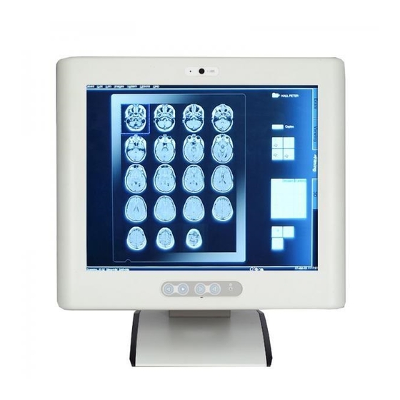
System Specification Dimensions I/O Outlets Package List General Description The MPC170-831-DC is a medical grade and fanless touch panel computer, and is equipped with a 17” TFT LCD display and low power ® ® ® consumption CPU, the LV Intel... - Page 14 Linux. For storage device, the MPC170-831- DC supports 2.5" HDD or USB-DOM. Medical-grade Product Design The MPC170-831-DC has an incredible design that can be used in different medical environments. Certify with Medical Certification Whole Unit IPX1 Water Resistant...
-
Page 15: System Specifications
MPC170-831-DC Series Panel PC User’s Manual System Specifications 1.2.1 Main CPU Board ® ® ® ® LV Intel Core2 Duo L7400 or ULV Intel Celeron M 423 System Chipset ® Intel 945GME + ICH7M BIOS Phoenix-Award BIOS, 4Mbit with RPL/PXE LAN Boot ROM,... -
Page 16: System Specification
MPC170-831-DC Series Panel PC User’s Manual 1.2.3 System Specification 17” SXGA TFT LCD Brightness -- 420 nits Resolution -- 1280 x 1024 Disk Drive Supports one 2.5” SATA HDD Power Supply ATX150W 24VDC Power Supply Power Input 18-36VDC, 10-5A Fuse Rating Fuse 3.15A/250V Slow Blow 5φ* 20mm Glass Body... -
Page 17: Dimensions
MPC170-831-DC Series Panel PC User’s Manual Dimensions The following diagrams show you dimensions and outlines of the MPC170-831-DC. Introduction... -
Page 18: I/O Outlets
MPC170-831-DC Series Panel PC User’s Manual I/O Outlets The following figures show you the locations of the MPC170-831-DC I/O outlets. Introduction... - Page 19 MPC170-831-DC Series Panel PC User’s Manual Connector Connector BRIGHTNESS ADJUST SPEAKER (R) VOLUME ADJUST PC/2 FOR K/B & M/S POWER LED VGA PORT MICROPHONE USB PORTS X 4 POWER SWITCH MIN-IN/LINE-OUT COM 1 DC POWER CONNECTOR ETHERNET PORT X 2...
-
Page 20: Packing List
MPC170-831-DC Series Panel PC User’s Manual Packing List The package bundled with your MPC170-831-DC should contain the following items: MPC170-831-DC Unit x 1 CD x 1 (For Driver and User’s Manual) Quick Manual x 1 CD-ROM Cover x 2 SATA cable x 1... -
Page 21: Chapter 2 Hardware Installation
The chapter 2 will show you how to install the hardware. It includes: Installing the the Hard Disk Drive The MPC170-831-DC offers a convenient drive bay module for users to install HDD. The MPC170-831-DC offers users one 2.5” Hard Disk Drive for installation. Please follow the steps: Step 1 Turn off the MPC170-831-DC. - Page 22 MPC170-831-DC Series Panel PC User’s Manual Step 3 Release 8 screws which are marked on the following picture. Hardware Installation...
- Page 23 MPC170-831-DC Series Panel PC User’s Manual Step 4 Remove the heatsink. Hardware Installation...
- Page 24 MPC170-831-DC Series Panel PC User’s Manual Step 5 Prepare HDD Assembly Parts HDD Bracket x 1 2.5inch HDD (Parallel ATA I/F) Screws x 4 Hardware Installation...
- Page 25 MPC170-831-DC Series Panel PC User’s Manual Step 6 Assembly the HDD with HDD bracket. Hardware Installation...
- Page 26 MPC170-831-DC Series Panel PC User’s Manual Step 7 Assembly the HDD assembly into MPC170 by following screws. Step 8 Plug-in the SATA & Power Cable to HDD. Hardware Installation...
- Page 27 MPC170-831-DC Series Panel PC User’s Manual Step 9 Assembly back the Heatsink. Hardware Installation...
-
Page 28: Installing The Add-On Card
MPC170-831-DC Series Panel PC User’s Manual Installing the Add-On Card If you need to install an Add-On card, please follow these steps for ADD-On card installation: Step 1 Turn off the MPC170-831-DC. Step 2 Unplug the DC power cable. Step 3 Release 8 screws which are marked on the following picture. - Page 29 MPC170-831-DC Series Panel PC User’s Manual Step 4 Remove the heatsink. Hardware Installation...
- Page 30 MPC170-831-DC Series Panel PC User’s Manual Step 5 Remove the two screws of IO Cover. Hardware Installation...
- Page 31 MPC170-831-DC Series Panel PC User’s Manual Step 6 Release the PCI Holder and Dummy Plate. Hardware Installation...
- Page 32 MPC170-831-DC Series Panel PC User’s Manual Step 7 Install the Add-On Card. Hardware Installation...
- Page 33 MPC170-831-DC Series Panel PC User’s Manual Step 8 Screw back the PCI Holder. Hardware Installation...
- Page 34 MPC170-831-DC Series Panel PC User’s Manual Step 9 Install back the IO Cover & Heatsink. Hardware Installation...
-
Page 35: Mountings - Wallmount/Vesa
MPC170-831-DC Series Panel PC User’s Manual Mountings – Wallmount/VESA The MPC170-831-DC provides mounting for Wallmount and VESA- Arm by applying Wallmount/VESA Bracket as below. Hardware Installation... -
Page 36: Installing Desktop Stand (Optional)
MPC170-831-DC Series Panel PC User’s Manual Installing Desktop Stand (Optional) The MPC170-831-DC provides Desktop Stand (Option) that customer can install as below. Step 1 Prepare the parts of Desktop Stand. Hardware Installation... - Page 37 MPC170-831-DC Series Panel PC User’s Manual Screw A Screw B Screw C Screw D Hardware Installation...
- Page 38 MPC170-831-DC Series Panel PC User’s Manual Step 2 Assembly the Desktop Stand. Step 2-1 Assembly the Backplane (Use Screw C). Hardware Installation...
- Page 39 MPC170-831-DC Series Panel PC User’s Manual Step 2-2 Assembly the Hinge Cover (Use Screw A). Hardware Installation...
- Page 40 MPC170-831-DC Series Panel PC User’s Manual Step 2-3 Assembly the Base (Use Screw D). Hardware Installation...
- Page 41 MPC170-831-DC Series Panel PC User’s Manual Step 3 Assembly the Desktop Stand onto MPC170-831-DC (Use Screw B). Hardware Installation...
-
Page 42: Installing Memory Module
MPC170-831-DC Series Panel PC User’s Manual Installing Memory Module Step 1 Turn-off the MPC170-831-DC. Step 2 Un-plug the DC power cable. Step 3 Release 8 screws which are marked on the following picture. Hardware Installation... - Page 43 MPC170-831-DC Series Panel PC User’s Manual Step 4 Remove the heatsink. Hardware Installation...
- Page 44 MPC170-831-DC Series Panel PC User’s Manual Step 5 Install the Memory Module. Hardware Installation...
- Page 45 MPC170-831-DC Series Panel PC User’s Manual Step 6 Install the Heatsink. Hardware Installation...
-
Page 46: Installing Wireless Module (Optional)
MPC170-831-DC Series Panel PC User’s Manual Installing Wireless Module (Optional) You can follow the steps below to install an optional wireless module. Step 1 Turn-off the MPC170-831-DC. Step 2 Un-plug the DC power cable Step 3 Release 8 screws which are marked on the following picture. - Page 47 MPC170-831-DC Series Panel PC User’s Manual Step 4 Remove the heatsink. Hardware Installation...
- Page 48 MPC170-831-DC Series Panel PC User’s Manual Step 5 Install Wireless Module & Plug-In the Antenna. Hardware Installation...
- Page 49 MPC170-831-DC Series Panel PC User’s Manual Step 6 Install back the Heatsink. Hardware Installation...
- Page 50 MPC170-831-DC Series Panel PC User’s Manual MEMO Hardware Installation...
-
Page 51: Chapter 3 Phoenix-Award Bios Utility
MPC170-831-DC Series Panel PC User’s Manual C h a p t e r 3 Phoenix-Award BIOS Utility The Phoenix-Award BIOS provides users with a built-in Setup program to modify basic system configuration. All configured parameters are stored in a battery-backed-up RAM (CMOS RAM) to save the Setup information whenever the power is turned off. -
Page 52: Control Keys
MPC170-831-DC Series Panel PC User’s Manual Control Keys Move cursor to the previous item Up arrow Move cursor to the next item Down arrow Move cursor to the item on the left hand Left arrow Move to the item in the right hand... -
Page 53: The Main Menu
MPC170-831-DC Series Panel PC User’s Manual The Main Menu Once you enter the Award BIOS CMOS Setup Utility, the Main Menu appears on the screen. In the Main Menu, there are several Setup functions and a couple of Exit options for your selection. Use arrow keys to select the Setup Page you intend to configure then press <Enter>... -
Page 54: Standard Cmos Setup Menu
MPC170-831-DC Series Panel PC User’s Manual Standard CMOS Setup Menu The Standard CMOS Setup Menu displays basic information about your system. Use arrow keys to highlight each item, and use <PgUp> or <PgDn> key to select the value you want in each item. - Page 55 MPC170-831-DC Series Panel PC User’s Manual <PgUp>/<+> or <PgDn>/<−> to select a numbered hard disk type, or directly type the number and press <Enter>. Please be noted your drive’s specifications must match the drive table. The hard disk will not work properly if you enter improper information. If your hard disk drive type does not match or is not listed, you can use Type User to manually define your own drive type.
- Page 56 MPC170-831-DC Series Panel PC User’s Manual Halt On This item determines whether the system will halt or not, if an error is detected while powering up. No errors The system booting will halt on any errors detected. (default) All errors Whenever BIOS detects a non-fatal error, the system will stop and you will be prompted.
-
Page 57: Advanced Bios Features
MPC170-831-DC Series Panel PC User’s Manual Advanced BIOS Features This section allows you to configure and improve your system, to set up some system features according to your preference. CPU Feature Scroll to this item and press <Enter> to view the CPU Feature sub menu. - Page 58 MPC170-831-DC Series Panel PC User’s Manual Hard Disk Boot Priority Scroll to this item and press <Enter> to view the CPU Feature sub menu. Press <Esc> to return to the Advanced BIOS Features page. CPU L1 & L2 Cache These two options speed up memory access. However, it depends on the CPU/chipset design.
- Page 59 MPC170-831-DC Series Panel PC User’s Manual First/Second/Third Boot Device These items let you select the 1st, 2nd, and 3rd devices that the system will search for during its boot-up sequence. The wide range of selection includes Floppy, LS120, Hard Disk, CDROM, ZIP100, USB-FDD, USB-ZIP, USB-CDROM, LAN and Disabled.
- Page 60 MPC170-831-DC Series Panel PC User’s Manual Typematic Rate Setting This item determines the typematic rate of the keyboard. The default value is “Disabled”. Enable typematic rate and typematic delay Enabled programming. Disable typematic rate and typematic delay Disabled programming. The system BIOS will use default value of these 2 items, controlled by keyboard.
- Page 61 MPC170-831-DC Series Panel PC User’s Manual asked to enter a password. Do not type anything, just press <Enter> and it will disable the security. Once the security is disabled, the system will boot and you can enter Setup freely. APIC Mode...
-
Page 62: Advanced Chipset Features
MPC170-831-DC Series Panel PC User’s Manual Advanced Chipset Features Since the features in this section are related to the chipset on the CPU board and are completely optimized, you are not recommended to change the default settings in this setup table unless you are well oriented with the chipset features. - Page 63 MPC170-831-DC Series Panel PC User’s Manual PCI Express Root Port Func. Scroll to this item and press <Enter> to view the sub menu to decide the PCI Express Port. Press <Esc> twice to return to the Main Menu page. *** VGA Setting ***...
- Page 64 MPC170-831-DC Series Panel PC User’s Manual DVMT/Fixed Memory Size DVMT (Dynamic Video Memory Technology) allows you to select a maximum size of dynamic amount usage of the video memory. The system would configure the video memory dependent on your application.
-
Page 65: Integrated Peripherals
MPC170-831-DC Series Panel PC User’s Manual Integrated Peripherals This section allows you to configure your SuperIO Device, IDE Function and Onboard Device. OnChip IDE Device Scroll to this item and press <Enter> to view the sub menu OnChip IDE Device. - Page 66 MPC170-831-DC Series Panel PC User’s Manual of the optimal number of block read/writes per sector the drive can support. IDE DMA transfer access Automatic data transfer between system memory and IDE device with minimum CPU intervention. This improves data throughput and frees CPU to perform other tasks.
- Page 67 MPC170-831-DC Series Panel PC User’s Manual Onboard Device Scroll to this item and press <Enter> to view the sub menu Onboard Device. USB Controller Enable this item if you are using the USB in the system. You should disable this item if a higher-level controller is added.
- Page 68 MPC170-831-DC Series Panel PC User’s Manual Super IO Device Scroll to this item and press <Enter> to view the sub menu Super IO Device. Onboard FDC Controller Select Enabled if your system has a floppy disk controller (FDC) installed on the system board and you wish to use it.
-
Page 69: Power Management Setup
MPC170-831-DC Series Panel PC User’s Manual ECP Mode Use DMA Select a DMA channel for the parallel port for use during ECP mode. PWRON After PWR-Fail This item enables your computer to automatically restart or return to its operating status. - Page 70 MPC170-831-DC Series Panel PC User’s Manual [S1(POS)] The S1 sleep mode is a low power state. In this state, no system context is lost (CPU or chipset) and hardware maintains all system context. [S3(STR)] The S3 sleep mode is a lower power state where the...
- Page 71 MPC170-831-DC Series Panel PC User’s Manual Soft-Off by PWR-BTTN This option only works with systems using an ATX power supply. It also allows the user to define which type of soft power OFF sequence the system will follow. The default value is “Instant-Off”.
-
Page 72: Pnp/Pci Configuration Setup
MPC170-831-DC Series Panel PC User’s Manual 3.10 PnP/PCI Configuration Setup This section describes configuring the PCI bus system. PCI, or Personal Computer Interconnect, is a system which allows I/O devices to operate at speeds nearing the speed the CPU itself uses when communicating with its own special components. - Page 73 MPC170-831-DC Series Panel PC User’s Manual IRQ Resources When resources are controlled manually, assign each system interrupt to one of the following types in accordance with the type of devices using the interrupt: 1. Legacy ISA Devices compliant with the original PC AT bus specification, requiring a specific interrupt (such as IRQ4 for serial port 1).
-
Page 74: Pc Health Status
MPC170-831-DC Series Panel PC User’s Manual 3.11 PC Health Status This section supports hardware monitering that lets you monitor those parameters for critical voltages, temperatures and fan speed of the board. Current CPU Temperature These read-only fields reflect the functions of the hardware thermal sensor that monitors the chip blocks and system temperatures to ensure the system is stable. -
Page 75: Frequency/Voltage Control
MPC170-831-DC Series Panel PC User’s Manual 3.12 Frequency/Voltage Control This section is to control the CPU frequency and Supply Voltage, DIMM OverVoltage and AGP voltage. Auto Detect DIMM/PCI Clk This item automatically detects the clock speeds of the system memory installed as well as the PCI interface. The options available are Enabled and Disabled. -
Page 76: Load Optimized Defaults
MPC170-831-DC Series Panel PC User’s Manual 3.13 Load Optimized Defaults This option allows you to load the default values to your system configuration. These default settings are optimal and enable all high performance features. To load SETUP defaults value to CMOS SRAM, enter “Y”. If not, enter “N”. -
Page 77: Set Supervisor/User Password
MPC170-831-DC Series Panel PC User’s Manual 3.14 Set Supervisor/User Password You can set either supervisor or user password, or both of then. The differences between are: Supervisor password: can enter and change the options of the setup menus. User password: just can enter but do not have the right to change the options of the setup menus. -
Page 78: Save & Exit Setup
MPC170-831-DC Series Panel PC User’s Manual 3.15 Save & Exit Setup This allows you to determine whether or not to accept the modifications. Typing “Y” quits the setup utility and saves all changes into the CMOS memory. Typing “N” brigs you back to Setup utility. -
Page 79: Exit Without Saving
MPC170-831-DC Series Panel PC User’s Manual 3.16 Exit Without Saving Select this option to exit the Setup utility without saving the changes you have made in this session. Typing “Y” will quit the Setup utility without saving the modifications. Typing “N” will return you to Setup utility. - Page 80 MPC170-831-DC Series Panel PC User’s Manual MEMO Phoenix-Award BIOS Utility...
-
Page 81: Chapter 4 Driver Installation
C h a p t e r 4 Driver Installation System MPC170-831-DC supports Windows 2000/XP. To facilitate the installation of system driver, please carefully read the instructions in this chapter before start installing. Insert Driver CD and select the \ MPC170-831\Driver\.. -
Page 82: Touch Screen
MPC170-831-DC Series Panel PC User’s Manual Touch Screen 4.2.1 Specification Touch Screen For 8-wire analog resistive type Touch Screen Controller DMC9000 Communications RS-232 Baud Rate 19200 baud rate fixed Resolution 1024 x 1024 (10-bit A/D converter inside) Power Input 5V to 12V DC... -
Page 83: Driver Installation- Windows 98/2000/Xp/Ce.net/Xp-Embedded
MPC170-831-DC Series Panel PC User’s Manual 4.2.2 Driver Installation- Windows 98/2000/XP/CE.NET/XP-Embedded The touch screen of MPC170-831-DC provides a driver for use with Windows 2000/XP. To facilitate installation of the touch screen driver, you should read the instructions in this chapter carefully before you attempt installation. - Page 84 MPC170-831-DC Series Panel PC User’s Manual Select the “Standard Calibrate” tab Calibration: To adjust the display with touch panel, click “Calibration” and follow the calibrate point to do calibration; there are five points on screen for calibration. Press OK. Driver Installation...
Need help?
Do you have a question about the MPC170-831-DC and is the answer not in the manual?
Questions and answers