
Related Manuals for AXIOMTEK GOT315WL-845-PCT


Summary of Contents for AXIOMTEK GOT315WL-845-PCT
- Page 1 GOT315WL-845-PCT All-in-One 15.6” WXGA TFT Fanless PCT Multi-Touch PANEL PC User’s Manual...
-
Page 2: Disclaimers
Axiomtek does not make any commitment to update any information in this manual. Axiomtek reserves the right to change or revise this document and/or product at any time without notice. No part of this document may be reproduced, stored in a retrieval system, or transmitted in any forms or by any means, electronic, mechanical, photocopying, recording, among others, without prior written permission from Axiomtek Co., Ltd. -
Page 3: Safety Precautions
Most electronic components are sensitive to static electrical charge. Disconnect the power cord from the GOT315WL-845-PCT series prior to any installation. Be sure both the system and all external devices are turned off. Sudden surge of power could ruin sensitive components. Make sure the GOT315WL-845-PCT Series is properly grounded. -
Page 4: Table Of Contents
Table of Contents Disclaimers ..................... ii Safety Precautions ..................iii Section 1 Introduction ..........1 General Descriptions ................1 Specifications ..................2 Dimensions and Outlines ..............4 I/O Outlets .................... 6 Packing List ..................7 Section 2 Hardware and Installation ...... 9 Board Layout .................. - Page 5 3.4.1 North Bridge....................... 31 3.4.2 South Bridge ...................... 32 Security Menu ..................33 Boot Menu ..................34 Save & Exit Menu ................35 Section 4 Driver and Installation ......37 Operating System ................37 4.1.1 Installing System Drivers ................37 Touch Screen ..................
- Page 6 This page is intentionally left blank.
-
Page 7: Introduction
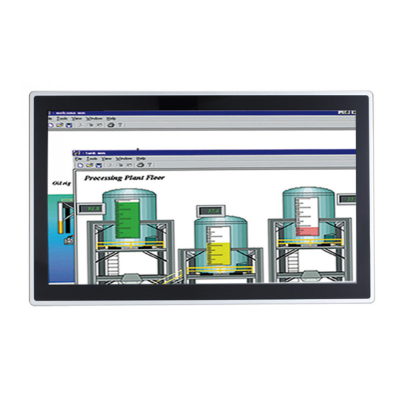
Packing List General Descriptions The GOT315WL-845-PCT adopts a 15.6-inch WXGA TFT LCD with 400-nit brightness and an Intel® Pentium® Processor N3710 (2M Cache, up to 2.56 GHz), providing excellent computing performance and thermal resistance. This fanless platform is especially designed for operation under a harsh environment including steel refinery, oil pipe, ship, machine maker, and many more. -
Page 8: Specifications
WLAN antenna supported (optional) The GOT315WL-845-PCT comes with 2 PCI Express Mini Card slots as an add-on option to connect a wireless LAN card under 802.11 a/b/g/n protocols, or with other 3G/GPRS applications, etc. These slots also come with 3 optional fixed rotational WLAN/3G antennas for wireless network connection. - Page 9 GOT315WL-845-PCT User’s Manual Power connector Phoenix power connector or screw power connector System Specifications 15.6” WXGA (1366x768) LCD with LED backlight Multi- PCAP touch A design of fanless heat dispensation IP65 aluminum front bezel ...
-
Page 10: Dimensions And Outlines
GOT315WL-845-PCT User’s Manual Dimensions and Outlines Diagram 1-1 shows the dimensions and outlines of the front panel of the GOT315WL-845-PCT Diagram 1-1 Front dimensions and outline of the GOT315WL-845-PCT Front dimensions: 396.81 x 247.12 x 59 mm Introduction... - Page 11 GOT315WL-845-PCT User’s Manual Diagram 1-2 Back outline of the GOT315WL-845-PCT Diagram 1-3 Cutting-out dimensions of the GOT315WL-845-PCT Cut out dimensions: 386.6 x 236.9 mm NOTE: The limited of wall depth is 9 mm in panel mount. Introduction...
-
Page 12: I/O Outlets
GOT315WL-845-PCT User’s Manual I/O Outlets Please refer to Figures 1-2 and 1-3 for I/O locations of the GOT315WL-845-PCT. Figure 1-2 Bottom view of the GOT315WL-845-PCT Figure 1-3 Side view of the GOT315WL-845-PCT Introduction... -
Page 13: Packing List
Power Adapter & power cord (AC adapter version only) Panel mount kit x 12 Screws for HDD x 2 SATA data cable x 1 SATA power cable x 1 Please contact an Axiomtek distributor immediately if any of the above-mentioned items is missing. Introduction... - Page 14 GOT315WL-845-PCT User’s Manual This page is intentionally left blank. Introduction...
-
Page 15: Hardware And Installation
GOT315WL-845-PCT User’s Manual Section 2 Hardware and Installation The GOT315WL-845-PCT provides rich I/O ports and flexible expansion for users to meet different demands; for example, in a case of CF card expansion. This Section describes hardware installation, including the following subsections: ... -
Page 16: Jumper And Connector Settings
Pins 1-2 open Pins 1-2 close Pins 1-2 close All pins open Before applying power to GOT315WL-845-PCT, please make sure all of the jumpers and connectors are in default position as listed in Table 2-1. Table 2-1 Factory mode of jumper settings... -
Page 17: Com Port Connector
No use Ethernet Connector There are two RJ-45 connectors, LAN1 and LAN2, inside the GOT315WL-845-PCT. Ethernet connection can be established by plugging one end of the Ethernet cable into this RJ-45 connector and the other end (phone jack) to a 1000/100/10-Base-T hub. -
Page 18: Mounting Methods
There are four ways to install the GOT315WL-845-PCT, namely: panel/ VESA/ wall/ desktop mount. The GOT315WL-845-PCT provides a standard panel mount kit. It can be installed by way of panel mount (see Figure 2-1, 2-2). Figure 2-1 Panel mount (back chassis) - Page 19 GOT315WL-845-PCT User’s Manual Alternatively, the GOT315WL-845-PCT can be installed by way of VESA mount which is in the dimensions of 100x100 mm. Simply fix four screws to fasten the kit from the back chassis, as shown in Diagram 2-3. Additionally, users can otherwise go for wall mount as an option, as shown in Diagram2-4.
-
Page 20: Hardware Installation
Hardware Installation 2.5.1 Installing a HDD The GOT315WL-845-PCT provides a convenient Hard Disk Drive (HDD) bracket for users to install a 2.5” SATA HDD. Please follow the steps: Step 1 Refer to Section 2.1 to open the back cover and dissemble the HDD tray by un-screwing the 2 screws (as shown in the red circles in Figure 2-5). - Page 21 GOT315WL-845-PCT User’s Manual Step 3 Lodge the two points on to the holes on the HDD tray (see red circles in Figure 2-7) and fix the bracket onto the HDD tray with two screws. Also, please make sure the two holes at the back of the HDD are embedded into the...
-
Page 22: Installing A Dram
GOT315WL-845-PCT User’s Manual 2.5.2 Installing a DRAM The GOT315WL-845-PCT provides one 204-pin DDR3L SODIMM socket that supports system memory up to 8GB. Please follow steps below to install a memory module: Step 1 Refer to Section 2.1 to open the back cover. -
Page 23: Installing A Wireless Lan Card
GOT315WL-845-PCT User’s Manual 2.5.3 Installing a Wireless LAN Card The GOT315WL-845-PCT comes with two Mini card slots for users to install wireless LAN cards. Users can choose either Slot 1 or Slot 2 to install the wireless LAN card. Please refer to the following instructions and illustration for the installation of the wireless LAN card. - Page 24 GOT315WL-845-PCT User’s Manual Step 3 Locate the antenna cable and connect it to the wireless LAN card (see Figure 2-13). Figure 2-13 Connecting the antenna to the wireless LAN card Step 4 Remove the antenna plug from the top of back cover, and then install the antenna on the antenna connector (see Figures 2-14 and 2-15).
-
Page 25: Connecting The Power Input
GOT315WL-845-PCT User’s Manual 2.5.4 Connecting the Power Input The GOT315WL-845-PCT is equipped with a Phoenix type of power connector which adopts 24VDC. Please follow the signs on the power connector to connect DC power source (see Figure 2-16). Figure 2-16 Power connector -:Power negative... - Page 26 GOT315WL-845-PCT User’s Manual This page is intentionally left blank. Hardware and Installation...
-
Page 27: Ami Bios Setup Utility
GOT315WL-845-PCT User’s Manual Section 3 AMI BIOS Setup Utility This Section provides users with detailed descriptions about how to set up basic system configurations through the AMI BIOS setup utility. Navigation Keys The BIOS setup/utility uses a key-based navigation system called hot keys. Most of the hot keys for the BIOS setup utility can be used at any time during the setup navigation process. -
Page 28: Main Menu
GOT315WL-845-PCT User’s Manual Main Menu Figure 3-1 Main menu System Date / Time Use this option to change the system time and date. Highlight System Time or System Date using the up/ down/ left and right arrow keys (see Figure 3-1). Enter new values through the keyboard. -
Page 29: Advanced Menu
GOT315WL-845-PCT User’s Manual Advanced Menu Figure 3-2 Advanced Menu The Advanced menu allows users to set configurations of the CPU and other system devices. Select any item on the left to go to the sub-menus (as shown in Figure 3-2). -
Page 30: Nct6106D Super Io Configuration
GOT315WL-845-PCT User’s Manual 3.3.1 NCT6106D Super IO Configuration The ‘NCT6106D Super IO Configuration’ page is to change the value of the Super IO Configuration. The description of the selected item will appear on the right side of the screen (as shown in Figure 3-3). For items marked with “”, please press <Enter> for further options (as shown in Figure 3-4). -
Page 31: Hardware Monitor
GOT315WL-845-PCT User’s Manual COM Port Type This option is used to select COM Port Type: RS-232/422/ or 485. Figure 3-4 ‘NCT6106D Super IO Configuration’ -> ‘Serial Port 1 (COM1)’ 3.3.2 Hardware Monitor Figure 3-5 shows a screen reflecting the health status of the hardware in real time. -
Page 32: Acpi Settings
GOT315WL-845-PCT User’s Manual 3.3.3 ACPI Settings This screen is used to select options of the ACPI Configuration, and change the value of the selected option. A description of the selected item appears on the right side of the screen. ACPI Sleep State This item allows users to select the Advanced Configuration and Power Interface (ACPI) state to be used for system suspension. -
Page 33: Cpu Configuration
GOT315WL-845-PCT User’s Manual 3.3.4 CPU Configuration Figure 3-7 shows a page of CPU configuration with item Intel Virtualization Technology [enable/disable] highlighted. Figure 3-7 Entering ‘CPU Configuration’ AMI BIOS Setup Utility... -
Page 34: Sata Configuration
GOT315WL-845-PCT User’s Manual 3.3.5 SATA Configuration This screen allows users to select options for SATA Configuration, and change the value of the selected option (see Figure 3-8). SATA Controller Highlight this item to set up SATA Controller to be Enable or Disable. -
Page 35: Usb Configuration
GOT315WL-845-PCT User’s Manual 3.3.6 USB Configuration Please see Figure 3-9 to see what items can be set up under the page of USB Configuration. Figure 3-9 Entering ‘USB Configuration’ 3.3.7 Utility Configuration Figure 3-10 shows the page once entering Utility Configuration. -
Page 36: Pcie/Msata Mini Card Configuration
GOT315WL-845-PCT User’s Manual 3.3.8 PCIE/mSATA Mini Card Configuration Highlighting item PCIE/mSATA Mini Card Configuration under the Advanced Menu, hit <Enter> to enter a sub-screen as shown in Figure 3-11. There are two choices for Mino Card Mode: PCIE and mSATA. -
Page 37: Chipset Menu
GOT315WL-845-PCT User’s Manual Chipset Menu The Chipset menu gives memory information about the North Bridge and TXE information about the South Bridge (see Figure 3-12). Figure 3-12 Chipset Menu 3.4.1 North Bridge Memory information about the North Bridge is show in Figure 3-13. -
Page 38: South Bridge
GOT315WL-845-PCT User’s Manual 3.4.2 South Bridge TXE information about the South Bridge is show in Figure 3-14. Figure 3-14 Entering ‘South Bridge’ AMI BIOS Setup Utility... -
Page 39: Security Menu
GOT315WL-845-PCT User’s Manual Security Menu Figure 3-15 Security Menu AMI BIOS Setup Utility... -
Page 40: Boot Menu
GOT315WL-845-PCT User’s Manual Boot Menu The Boot menu allows users to change boot options of the system. Users can highlight any of the items on the left frame of the screen to go to any particular sub menus (as shown in Figure 3-16). -
Page 41: Save & Exit Menu
GOT315WL-845-PCT User’s Manual Save & Exit Menu Figure 3-17 Save & Exit Menu AMI BIOS Setup Utility... - Page 42 GOT315WL-845-PCT User’s Manual This page is intentionally left blank. AMI BIOS Setup Utility...
-
Page 43: Driver And Installation
Section 4 Driver and Installation Operating System The GOT315WL-845-PCT is compatible with operating systems Windows 10 and Windows 10 IoT Enterprise. To facilitate the installation of system drivers, please carefully read the instructions in this Section before any of such installation. -
Page 44: Touch Screen
GOT315WL-845-PCT User’s Manual Touch Screen The GOT315WL-845-PCT is designed based on the technology of projected capacitive multi-touch screen of which specifications are listed below. The touch driver will be installed automatically and can drive the touch panel to get two fingers touch function that based on the Windows 10 and Windows 10 IoT Enterprise support.
Need help?
Do you have a question about the GOT315WL-845-PCT and is the answer not in the manual?
Questions and answers