Table of Contents
Advertisement
Quick Links
A Beijer Electronics Group Company
JetNet 2005/2005f Industrial Ethernet Switch
Quick Installation Guide V1.2
Overview
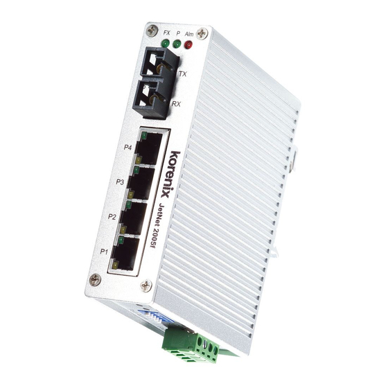
JetNet 2005/2005f Industrial Ethernet Switch supports 5 10/100Base TX (JetNet 2005) or 4
10/100TX plus one 100FX Ethernet port (JetNet 2005f ). In order to survive under harsh
environment, JetNet 2005/2005f chooses industrial-grade aluminum case with IP30 standard
protection.
It provides one relay output to alarm port break events, which is enabled/ disabled by the
dip switch. JetNet 2005/2005f is recommended to be powered by DC24V (18~32V) from
the 2-pin terminal block.
Package Check List
JetNet 2005/2005f Switch
Quick Installation Guide
Installation
Mounting the Unit
Din-Rail mount: Mount the din-rail clip screwed on the rear
of JetNet 2005/2005f on the DIN rail.
Grounding JetNet 2005/2005f Switch
ere is one grounding screw on the bottom side of
JetNet 2005/2005f. Connect the frame grounding of
Port Alam
switchto the grounding surface to ensure safety
andprevent noise to interfere communication.
Wiring the Power Inputs
1. Insert the positive and negative wires into the V+
Fault
and V- contact on the terminal block connector
2. Tighten the wire-clamp screws to prevent the DC
wires from being loosened.
Notes:
e recommended working voltage is DC24V
(DC18~ 32 V)
Wiring the Relay Output
e relay output alarm contacts are in the middle of
Fault
the terminal block connector as shown in the gure.
By inserting the wires and set the DIP switch of Port
Alarm to "ON", relay output alarm will detect any
port failures, and form a short circuit.
e alarm
relay output is "Normal Open".
Connecting to Network
1. Connecting the Ethernet Ports: Connect one end of an Ethernet cable into the UTP
port of JetNet 2005/2005f, while the other end is connected to the attached networking
device. All UTP ports support auto MDI/MDIX function.
Yellow for 10M Ethernet or Green for 100M Ethernet.
2. Connecting the Fiber Port (JetNet 2005f ): Connect the ber port on your JetNet
2005f to another Fiber Ethernet device, by following the gure below. Wrong connection
will cause the ber port not working properly.
ATTENTION
is is a Class 1 Laser/LED product.
!
Don't look into the Laser/LED Beam.
A Beijer Electronics Group Company
DIP Switch Settings for Alarm Relay Output
JetNet 2005/2005f Industrial Ethernet Switch
Quick Installation Guide V1.2
Overview
DIP Switch Settings for Alarm Relay Output
JetNet 2005/2005f Industrial Ethernet Switch supports 5 10/100Base TX (JetNet 2005) or 4
10/100TX plus one 100FX Ethernet port (JetNet 2005f ). In order to survive under harsh
environment, JetNet 2005/2005f chooses industrial-grade aluminum case with IP30 standard
protection.
It provides one relay output to alarm port break events, which is enabled/ disabled by the
dip switch. JetNet 2005/2005f is recommended to be powered by DC24V (18~32V) from
the 2-pin terminal block.
Package Check List
A Beijer Electronics Group Company
standard, supports 5 10/100Base TX (JetNet 2005) or 4 10/100TX plus one
e tNet 2005/2005f Industrial Ethernet Switch, conforming IEEE 802.3 and 802.3u
J
Overview
JetNet 2005/2005f Industrial Ethernet Switch
Quick Installation Guide V1.2
JetNet 2005/2005f Switch
case with IP30 standard protection.
under harsh environment, JetNet 2005/2005f chooses industrial-grade aluminum
design to save rail space of compact system requirement. In order to survive
100FX Ethernet port (JetNet 2005f). JetNet 2005/2005f adopts slim industrial
(18~32V) from the 2-pin terminal block.
by the dip switch. JetNet 2005/2005f is recommended to be powered by DC24V
Unpack the box, you will find
Package Check List
It provides one relay output to alarm port break events, which is enabled/ disabled
Pin No. # Status
Description
Quick Installation Guide
of JetNet 2005/2005f on the DIN rail.
Mounting the Unit
JetNet 2005/2005f Switch
Quick Installation Guide
Din-Rail mount: Mount the din-rail clip screwed on the rear
Installation
Mounting the Unit
Din-Rail mount: Mount the din-rail clip screwed on the rear
of JetNet 2005/2005f on the DIN rail.
ON
To enable port break alarm at this port.
P1 to P5
(Pin1 ~5)
O
To disable port break alarm at this port.
Support
5 Years Warranty
Fault V+ V- DC24
Each of Korenix's product line is designed, produced, and tested with high industrial
standard. Korenix warrants that the Product(s) shall be free from defects in materials and
workmanship for a period of ve (5) years from the date of delivery provided that the
Product was properly installed and used.
is warranty is voided if defects, malfunctions or failures of the warranted Product are
V+
V-
caused by damage resulting from force measure (such as oods, re, etc.), other external
Power Inputs
forces such as power disturbances, over spec power input, or incorrect cabling; or the
warranted Product is misused, abused, or operated, altered and repaired in an unauthorized
or improper way.
Attention! To avoid system damage caused by sparks, please DO NOT plug in power
connector when power is on.
e product is in compliance with Directive 2002/95/EC and 2011/65/EU of the European
V+
V-
Parliament and of the Council of 27 January 2003 on the restriction of the use of certain
Relay Output,
hazardous substances in electrical and electronics equipment(RoHS Directives & RoHS 2.0)
Carry ability
1A @24V
Korenix Customer Service
KoreCARE is Korenix Technology's global service center, where our professional sta s are
ready to solve your problems at any time Korenix global service center's e-mail is
e LNK / ACT LED will turn
KoreCARE@korenix.com.
For more information and documents download please visit our website:
http://www.korenix.com/downloads.htm
RX
RX
TX
TX
Cable Wiring(SC to SC)
TX A
RX B
RX A
TX B
Alarm Switch
1 2
3
4
5
Advertisement
Table of Contents

Subscribe to Our Youtube Channel
Related Manuals for Korenix JetNet 2005f


Summary of Contents for Korenix JetNet 2005f
- Page 1 Overview http://www.korenix.com/downloads.htm 2. Connecting the Fiber Port (JetNet 2005f ): Connect the ber port on your JetNet JetNet 2005/2005f Industrial Ethernet Switch supports 5 10/100Base TX (JetNet 2005) or 4 2005f to another Fiber Ethernet device, by following the gure below. Wrong connection 10/100TX plus one 100FX Ethernet port (JetNet 2005f ).
- Page 2 JetNet 2005/2005f Industrial Ethernet Switch supports 5 10/100Base TX (JetNet 2005) or 4 P1 to P5 10/100TX plus one 100FX Ethernet port (JetNet 2005f ). In order to survive under harsh environment, JetNet 2005/2005f chooses industrial-grade aluminum case with IP30 standard ...
Need help?
Do you have a question about the JetNet 2005f and is the answer not in the manual?
Questions and answers