VIA Technologies AMOS-820 User Manual
Fanless ultra-compact quad-core
edge computing system ruggedized for
extreme environments
Hide thumbs
Also See for AMOS-820:
- Manual (49 pages) ,
- User manual (28 pages) ,
- Quick start manual (27 pages)

Subscribe to Our Youtube Channel
Related Manuals for VIA Technologies AMOS-820


Summary of Contents for VIA Technologies AMOS-820
- Page 1 USER MANUAL VIA AMOS-820 Fanless ultra-compact quad-core Edge Computing system ruggedized for extreme environments 1.21-11212018-153100...
- Page 2 VIA Technologies, Inc. reserves the right the make changes to the products described in this manual at any time without prior notice. Regulatory Compliance FCC-A Radio Frequency Interference Statement This equipment has been tested and found to comply with the limits for a class A digital device, pursuant to part 15 of the FCC rules.
- Page 3 Battery Recycling and Disposal Only use the appropriate battery specified for this product. Do not re-use, recharge, or reheat an old battery. Do not attempt to force open the battery. Do not discard used batteries with regular trash. Discard used batteries according to local regulations. Safety Precautions Always read the safety instructions carefully.
- Page 4 VIA AMOS-820 User Manual Box Contents VIA AMOS-820-QP SKU 1 x VIA AMOS-820 system (with 1.0GHz NXP i.MX 6QuadPlus Cortex-A9 SoC) 1 x Phoenix plug to DC jack 1 x COM/CAN conversion cable 1 x COM port cable 1 x Screw pack for miniPCIe card...
- Page 5 VIA AMOS-820 User Manual Optional Accessories Wireless Accessories Part Number Description 00GO27100BU2B0D0 VNT9271BU0DB IEEE 802.11 b/g/n USB Wi-Fi dongle VAB-820-W-M IEEE 802.11b/g/n miniPCIe Wi-Fi & Bluetooth module EMIO-2531-00A1 with assembly kit and antenna EMIO-2550-00A1 3.75G HSPA/UMTS mobile broadband full size miniPCIe module with...
-
Page 6: Table Of Contents
4. Hardware Installation ........................ 16 4.1. Installing the Micro SD Card ..........................16 4.2. Installing the Rubber Feet ..........................17 4.3. Mounting the VIA AMOS-820 System ......................18 5. Software and Technical Supports ................... 19 5.1. Android and Linux Support..........................19 5.2. Technical Supports and Assistance ......................19 Appendix A. - Page 7 VIA AMOS-820 User Manual A.2. Installing VIA EMIO-2531 miniPCIe Wi-Fi & Bluetooth Module ..............21 A.3. Installing VIA EMIO-2550 Mobile Broadband Module................26...
- Page 8 Figure 1: Front panel I/O layout ............................6 Figure 2: Back panel I/O layout ............................6 Figure 3: Dimensions of the VIA AMOS-820 (front view) ..................7 Figure 4: Dimensions of the VIA AMOS-820 (top view) .....................7 Figure 5: Dimensions of the VIA AMOS-820 (rear view) ....................7 Figure 6: DC-in jack diagram ..............................8...
- Page 9 VIA AMOS-820 User Manual List of Tables Table 1: DC-in jack pinouts ...............................8 Table 2: CAN/COM2 port pinouts ...........................9 Table 3: COM1 port pinouts ............................10 Table 4: USB 2.0 port pinouts ............................11 Table 5: Micro USB 2.0 OTG port pinouts ........................11 Table 6: Audio jack receptacle pinouts ........................
-
Page 10: Product Overview
VIA AMOS-820. 1.1.4. Optimize Integration with Multiple I/O Access With front and back I/O access, the VIA AMOS-820 can be easily configured to support a wide variety of applications with easy integration and quick setup. -
Page 11: Wide Range Of Operating Temperature
The VIA AMOS-820 is equipped with an optional integrated Powered Device (PD) controller and switching regulator intended for high-power IEEE 802.3at and 802.3af applications. The power over Ethernet (PoE) PD board can output 25W of power. The VIA AMOS-820 can be operated using either PoE or external adaptors (12V). -
Page 12: Product Specifications
1GB DDR3 SDRAM onboard Storage 4GB eMMC Flash memory Boot Loader 4MB SPI Serial Flash ROM Graphics o Vivante GC2000+ GPU (AMOS-820-QP SKU) / Vivante GC2000 GPU (AMOS-820 SKU) • Three independent, integrated graphics processing units • Supports an OpenGL ®... - Page 13 2 x Antenna holes for 3G/Wi-Fi Power Supply 12V DC-in (typical: 7W) Smart ETK o Watchdog timer, CAN bus, GPIO, UART PoE Function o Supports IEEE802.3at compliant (type 2) PD (AMOS-820-2Q10A1, AMOS-820-6Q10A1) Mechanical Construction • Aluminum top cover • Metal chassis housing •...
- Page 14 VIA AMOS-820 User Manual Operating System o Android 6.0, Linux kernel 4.1.15 Notes: As the operating temperature provided in the specifications is a result of testing performed in VIA’s chamber, a number of variables can influence this result. Please note that the working temperature may vary depending on the actual situation and environment.
-
Page 15: Layout Diagram
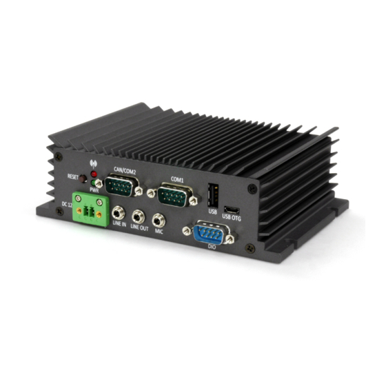
VIA AMOS-820 User Manual 1.3. Layout Diagram Figure 1: Front panel I/O layout Figure 2: Back panel I/O layout... -
Page 16: Product Dimensions
VIA AMOS-820 User Manual 1.4. Product Dimensions Figure 3: Dimensions of the VIA AMOS-820 (front view) Figure 4: Dimensions of the VIA AMOS-820 (top view) Figure 5: Dimensions of the VIA AMOS-820 (rear view) -
Page 17: External I/O Pin Descriptions And Functionality
VIA AMOS-820 User Manual 2. External I/O Pin Descriptions and Functionality The VIA AMOS-820 has a wide selection of interfaces. It includes a selection of frequently-used ports as part of the external I/O coastline. 2.1. DC-In Jack The VIA AMOS-820 comes with a 2-pole Phoenix DC jack on the front panel that carries 12V external power input. -
Page 18: Led Indicator
VIA AMOS-820 User Manual 2.3. LED Indicator There are two LEDs on the front panel of the VIA AMOS-820 that indicate the status of the system: • Power LED is green and indicates the status of the system’s power. • WPAN/WWAN/Wi-Fi LED is red and indicates network status of the system. -
Page 19: Com1 Port
VIA AMOS-820 User Manual 2.5. COM1 Port The integrated 9-pin COM port uses a male DE-9 connector. The COM1 port supports the RS-232 standard. The pinouts of the COM1 port are shown below. Figure 10: COM1 port diagram Signal DCD1... -
Page 20: Usb 2.0 Port
Figure 12: Micro USB 2.0 OTG port diagram Signal VBUS Table 5: Micro USB 2.0 OTG port pinouts Note: The VIA AMOS-820 Micro USB 2.0 OTG port is regarded as an USB device by default when connected to a USB host. -
Page 21: Audio Jack
Table 6: Audio jack receptacle pinouts 2.9. DIO Port The VIA AMOS-820 comes with a 9-pin DIO port which uses a male DE-9 connector. It offers Digital IO communication interface port to support 8-bit GPIO. The pinouts of the DIO port are shown below. -
Page 22: Micro Sd/Spi Boot Switch
Figure 15: Micro SD/SPI boot switch diagram 2.11. Gigabit Ethernet Port The VIA AMOS-820 comes with one Gigabit Ethernet port on the back panel which uses an 8 Position and 8 Contact (8P8C) receptacle connector commonly known as RJ-45. It is fully compliant with the IEEE 802.3 (10BASE-T), 802.3u (100BASE-TX), and 802.3ab (1000BASE-T) standards. -
Page 23: Hdmi ® Port
2.13. Composite RCA Jack The VIA AMOS-820 is equipped with a Composite RCA jack labeled as “AV IN” on the back panel. The Composite RCA jack connects to external composite video input device. Figure 18: Composite RCA jack diagram... -
Page 24: Onboard I/O
3.2. Micro SD Card Slot The VIA AMOS-820 comes with a Micro SD card slot located on the bottom side of the chassis. The Micro SD card slot offers expandable storage of Micro SD card memory up to 32GB capacity. -
Page 25: Hardware Installation
VIA AMOS-820 User Manual 4. Hardware Installation This chapter provides information about the hardware installation procedures. It is recommended to use a grounded wrist strap before handling computer components. Electrostatic discharge (ESD) can damage some components. 4.1. Installing the Micro SD Card Step 1 Locate the bottom access cover of the chassis. -
Page 26: Installing The Rubber Feet
VIA AMOS-820 User Manual 4.2. Installing the Rubber Feet Step 1 Locate the area where to install the rubber feet. Step 2 Attach carefully each rubber foot. Firmly press it down to ensure the rubber foot is properly in place. -
Page 27: Mounting The Via Amos-820 System
820 system can be mounted on walls, tables or any flat surface suitable for mounting. Reminders: Make sure to remove the rubber feet before mounting the VIA AMOS-820 system. The rubber feet are not required when mounting the system on walls or tables. -
Page 28: Software And Technical Supports
VIA AMOS-820 User Manual 5. Software and Technical Supports 5.1. Android and Linux Support The VIA AMOS-820 features a complete software evaluation image featuring the Android and Linux kernel operating systems. Android 6.0, Linux kernel 4.1.15 5.2. Technical Supports and Assistance •... -
Page 29: Appendix A. Installing Wireless Accessories
Appendix A. Installing Wireless Accessories This chapter provide information on how to install the VNT9271 USB Wi-Fi dongle, EMIO-2531 miniPCIe Wi-Fi & Bluetooth module and EMIO-2550 miniPCIe mobile broadband module in the VIA AMOS-820 system. A.1. Installing the VNT9271 USB Wi-Fi Dongle Step 1 Locate a USB 2.0 port on the front or back panel I/O. -
Page 30: Figure 26: Removing The Bottom Access Cover
VIA AMOS-820 User Manual A.2. Installing VIA EMIO-2531 miniPCIe Wi-Fi & Bluetooth Module Step 1 Take off the screw of VIA EMIO-2531 to remove the bottom access cover. Figure 26: Removing the bottom access cover Step 2 Remove the screw and nut from the EMIO-2531 module as shown in the figure below. -
Page 31: Figure 28: Installing The Emio-2531 Module
VIA AMOS-820 User Manual Step 3 Align the notch on the EMIO-2531 module with its counterpart on the miniPCIe slot. Then insert the module at a 30° angle. Figure 28: Installing the EMIO-2531 module Step 4 Once the module has been inserted, push down the module until the screw hole aligns with the mounting hole on the standoff. -
Page 32: Figure 30: Removing The Screws Of The Top Cover Chassis, And Front, Back And Bottom Panel Plates
VIA AMOS-820 User Manual Step 5 Loosen the thirteen screws of the front, back and bottom plates. Figure 30: Removing the screws of the top cover chassis, and front, back and bottom panel plates Step 6 Carefully pull the back panel plate and the top cover chassis. Then remove the antenna hole cover. -
Page 33: Figure 32: Installing Wi-Fi Antenna Cable And Antenna
VIA AMOS-820 User Manual Step 7 Insert the Wi-Fi antenna cable into the antenna hole from inside of the back panel plate. Insert the washer, fasten it with the nut, and install the antenna. Pull the other end of the Wi-Fi antenna cable and insert it to the available space going down to the bottom side of the board. -
Page 34: Figure 34: Reinstalling Bottom Access Cover
VIA AMOS-820 User Manual Step 9 Reinstall the bottom access cover. Figure 34: Reinstalling bottom access cover... -
Page 35: Figure 35: Removing The Bottom Access Cover
VIA AMOS-820 User Manual A.3. Installing VIA EMIO-2550 Mobile Broadband Module Step 1 Take off the screw of VIA EMIO-2550 to remove the bottom access cover. Figure 35: Removing the bottom access cover Step 2 Remove the thirteen screws of the top cover chassis, and front, back and bottom panel plates. -
Page 36: Figure 37: Pulling Out The Top Cover Chassis, Back Panel Plate, And Removing The Antenna Holes Cover
VIA AMOS-820 User Manual Step 3 Pull the back panel plate and the top cover chassis. Then remove the antenna holes cover. Figure 37: Pulling out the top cover chassis, back panel plate, and removing the antenna holes cover Step 4 Insert the 3G and GPS antenna cables into the antenna holes from the inside of the back panel plate. -
Page 37: Figure 39: Inserting The 3G Sim Card
VIA AMOS-820 User Manual Step 5 On the bottom side of the EMIO-2550 module, insert the 3G SIM card to the SIM card slot. Figure 39: Inserting the 3G SIM card Step 6 Connect the other end of the GPS antenna cable to the micro-RF connector labeled “GPS” on the bottom side of the EMIO-2550 module (EMIO-2550-00A1). -
Page 38: Figure 41: Installing The Emio-2550 Module
VIA AMOS-820 User Manual Step 7 Align the notch on the EMIO-2550 module with its counterpart on the miniPCIe slot. Then insert the module at a 30° angle. Figure 41: Installing the EMIO-2550 module Step 8 Once the EMIO-2550 module has been fully inserted, push down the module until the screw hole aligns with the mounting hole on the standoff. -
Page 39: Figure 43: Connecting The 3G Antenna Cable To The Micro-Rf Connecter On The Emio-2550
VIA AMOS-820 User Manual Step 9 Connect the other end of the 3G antenna cable to the micro-RF connector labeled “MAIN” on the EMIO- 2531 module. Figure 43: Connecting the 3G antenna cable to the micro-RF connecter on the EMIO-2550 Step 10 Reinstall the bottom access cover.
Need help?
Do you have a question about the AMOS-820 and is the answer not in the manual?
Questions and answers