VIA Technologies AMOS-825 User Manual
Fanless ultra-compact quad-core arm system ruggedized for demanding transportation environments
Hide thumbs
Also See for AMOS-825:
- Quick start manual (22 pages) ,
- Quick start manual (22 pages) ,
- Quick start manual (22 pages)

Related Manuals for VIA Technologies AMOS-825


Summary of Contents for VIA Technologies AMOS-825
- Page 1 USER MANUAL VIA AMOS-825 Fanless ultra-compact quad-core ARM system ruggedized for demanding transportation environments 1.07-09272018-161500...
- Page 2 VIA Technologies, Inc. reserves the right the make changes to the products described in this manual at any time without prior notice. Regulatory Compliance FCC-A Radio Frequency Interference Statement This equipment has been tested and found to comply with the limits for a class A digital device, pursuant to part 15 of the FCC rules.
- Page 3 Do not cover the ventilation holes. The openings on the enclosure protect the equipment from overheating WARNING: WARNING The operating temperature of VIA AMOS-825 is from 0°C to 60°C, please must installed the device in a restricted access location HOT SURFACE to avoid the hot surface of housing, and make more aware of DO NOT TOUCH potential hazards and reduce the risk.
- Page 4 7” Projective capacitive touch monitor (800x480, -20°C ~ 70°C) Wireless Accessories Part Number Description EMIO-2550-00A1 3.75G HSPA/UMTS mobile broadband full size miniPCIe module with GPS, SIM card slot, assembly kit and antenna (Note: GPS function is not supported - VIA AMOS-825 already includes GPS support)
-
Page 5: Table Of Contents
4.3. Installing the miniPCIe WPAN/WWAN/WLAN module and antenna ..........17 4.4. Installing the rubber feet ..........................21 4.5. Mounting the VIA AMOS-825 system ......................22 4.6. Connecting the LCD touch screen monitor ....................23 4.7. Unplugging the monitor cable ........................25 5. Software and Technical Supports ................... 26 5.1. - Page 6 Figure 32: Mounting the VIA AMOS-825 system ....................... 22 Figure 33: Connecting the other end of the monitor’s cable to the LCD monitor ..........23 Figure 34: Connecting the monitor’s cable to the VIA AMOS-825 system ............24 Figure 35: Unlocking the monitor’s cable head ......................25 Figure 36: Unplugging the monitor’s cable head ......................
- Page 7 VIA AMOS-825 User Manual List of Tables Table 1: DC-in jack pinouts ...............................8 Table 2: SCSI connector pinouts ............................9 Table 3: Micro USB 2.0 OTG port pinouts ........................10 Table 4: COM/CAN port pinouts ..........................10 Table 5: USB 2.0 ports pinouts ............................11 Table 6: Gigabit Ethernet port pinouts ........................
-
Page 8: Product Overview
Front and back panel I/O access enables the VIA AMOS-825 to easily support various applications as well as for easy integration and quick setup. 1.1.7. Storage Expansion The Micro SD card slot enables the VIA AMOS-825 to have a flexible storage of Micro SD card memory. -
Page 9: Shock And Vibration Resistant
Support multiple methods for mounting the chassis securely. The rugged embedded system can be mounted to a side-panel of a car, floor bed, or any flat surface. 1.1.11. Embedded Operating System Ready The VIA AMOS-825 features a complete evaluation image featuring Android 6.0 operating system. -
Page 10: Product Specifications
VIA AMOS-825 User Manual 1.2. Product Specifications Processor o 1.0GHz NXP i.MX 6Quad ARM Cortex-A9 SoC System Memory o 1GB DDR3 SDRAM onboard Storage o 16GB eMMC Flash memory Boot Loader o 4MB SPI Flash ROM Graphics o Vivante GC2000 GPU Three independent, integrated 3D/2D and video graphics processing units ®... - Page 11 VIA AMOS-825 User Manual Back Panel I/O o 1 x Gigabit Ethernet port o 2 x USB 2.0 ports o 1 x Antenna connector for Wi-Fi/Bluetooth o 1 x Antenna connector for GPS Bottom Side (open window with removable cover)
- Page 12 VIA AMOS-825 User Manual o Vibration Loading during Operation (with onboard eMMC) • 7Grms, IEC 60068-2-64, random, 5 ~ 500Hz, 1hr/axis o Shock During Operation (with onboard eMMC) • 70G, IEC 60068-2-27, half size, 11ms duration Compliance o CE, FCC Operating System o Android 6.0...
-
Page 13: Layout Diagram
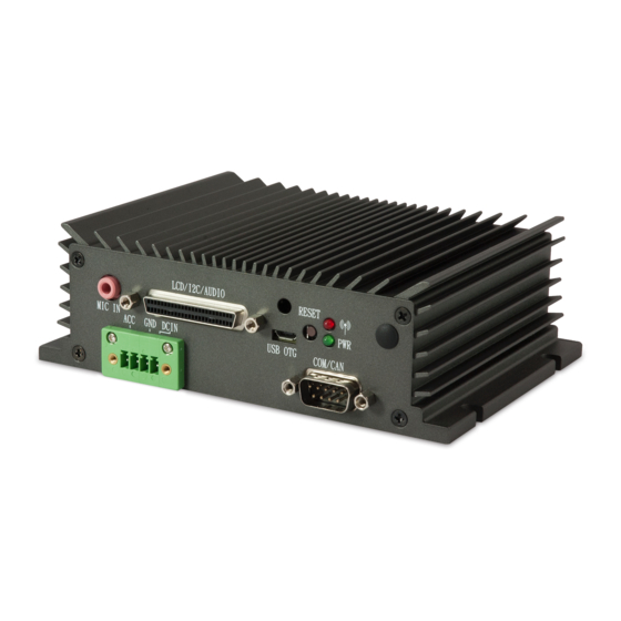
VIA AMOS-825 User Manual 1.3. Layout Diagram SCSI connector Reset (LCD/I C/Audio) WPAN/WWAN/WLAN LED Antenna hole MIC IN LCD / I C / AUDIO Mic-in RESET Power LED GND DCIN USB OTG COM/CAN COM/CAN DC-in Micro USB 2.0 OTG Figure 1: Front panel I/O layout USB 2.0... -
Page 14: Product Dimensions
LCD / I C / AUDIO RESET 48.1mm 41.7mm 5.2mm GND DCIN USB OTG COM/CAN 9.6mm Figure 3: Dimensions of the VIA AMOS-825 (front view) WiFi/BT 124.5mm 132.5mm 136.12mm 150.5mm Figure 4: Dimensions of the VIA AMOS-825 (rear view) 21.02mm 101.3mm 103.3mm... -
Page 15: External I/O Pin Descriptions And Functionality
ACC (Automatic Combustion Control) Table 1: DC-in jack pinouts 2.2. Reset Button The VIA AMOS-825 comes with a reset button on the front panel. The reset button allows the user to reboot or reset the system forcibly. Figure 7: Reset button diagram 2.3. -
Page 16: Mic-In Jack
VIA AMOS-825 User Manual 2.4. Mic-in Jack The Mic-in jack receptacle is used to attach a microphone. The jack receptacle can fit a 3.5mm Tip Ring Sleeve (TRS) connector. Mic-in Figure 9: Mic-in jack receptacle diagram ² 2.5. SCSI Connector (LCD/I C/Audio) The SCSI connector is a 50-pin D-sub connector located on the front panel. -
Page 17: Micro Usb 2.0 Otg Port
2.6. Micro USB 2.0 OTG Port The VIA AMOS-825 comes with a Micro USB 2.0 OTG port (Micro USB Type B connector) located on the front panel. The Micro USB 2.0 OTG port supports OTG (On-The-Go). The pinouts of the Micro USB 2.0 OTG port are shown below. -
Page 18: Usb 2.0 Ports
VIA AMOS-825 User Manual 2.8. USB 2.0 Ports The VIA AMOS-825 provides two USB 2.0 ports located on the back panel. Each USB port gives complete Plug and Play and hot swap capability for external devices. The USB interface complies with USB UHCI, Rev. -
Page 19: Onboard I/O
This chapter provides information about the onboard I/O on the VIA AMOS-825 system’s mainboard. 3.1. MiniPCIe Slot The VIA AMOS-825 is equipped with a miniPCIe slot for wireless networking option such as WPAN/WWAN/WLAN. The miniPCIe slot is compatible with miniPCIe 2.0 module that is full-length or half-length. -
Page 20: Micro Sd Card Slot
VIA AMOS-825 User Manual 3.2. Micro SD Card Slot The VIA AMOS-825 comes with a Micro SD card slot with support for a maximum storage capacity of 32GB. The pinouts of the Micro SD card slot are shown below. Figure 16: Micro SD card slot diagram... -
Page 21: Hardware Installation
VIA AMOS-825 User Manual 4. Hardware Installation This chapter provides information about hardware installation procedures. 4.1. Installing the GPS and Wi-Fi/Bluetooth antenna Step 1 Install the GPS and Wi-Fi/Bluetooth antennas to the antenna connectors respectively as shown in the figure below. -
Page 22: Installing The Micro Sd Card
VIA AMOS-825 User Manual 4.2. Installing the Micro SD card Step 1 Locate the bottom window access cover of the chassis. Loosen the screw to remove the cover. Figure 20: Unscrewing of bottom access cover Step 2 Remove the bottom window access cover. -
Page 23: Figure 22: Inserting The Micro Sd Card
VIA AMOS-825 User Manual Step 3 Gently insert the Micro SD card into the card slot with the label side facing down then press the card until it locks into place. Figure 22: Inserting the Micro SD card Note: To remove the Micro SD card, press the card to disengage from the slot reader then gently pull out the card. -
Page 24: Installing The Minipcie Wpan/Wwan/Wlan Module And Antenna
VIA AMOS-825 User Manual 4.3. Installing the miniPCIe WPAN/WWAN/WLAN module and antenna Step 1 Insert the SIM card on the bottom side of the miniPCIe module (EMIO-2550-00A1). Note: The Step 1 is only intended for installing of the SIM card on the EMIO-2550-00A1 module. Should the users be using a different module, they can skip Step 1 and go directly to Step 2. -
Page 25: Figure 25: Unscrewing The Front Panel I/O Plate
VIA AMOS-825 User Manual Step 4 Loosen four screws of the front panel I/O plate. Figure 25: Unscrewing the front panel I/O plate Step 5 Remove the hex standoff screws of COM/CAN port and SCSI connector. Figure 26: Removing the hex standoff screws... -
Page 26: Figure 27: Removing The Front Panel I/O Plate And The Antenna Hole Cover
VIA AMOS-825 User Manual Step 6 Pull the front panel I/O plate then remove the WPAN/WWAN/WLAN antenna hole cover. / A U Figure 27: Removing the front panel I/O plate and the antenna hole cover Step 7 Insert the WPAN/WWAN/WLAN antenna cable into the antenna hole from the inside of the front panel plate. -
Page 27: Figure 29: Connecting The Wpan/Wwan/Wlan Antenna Cable To The Micro-Rf Connector
VIA AMOS-825 User Manual Step 8 Gently connect the other end of the WPAN/WWAN/WLAN antenna cable to the micro-RF connector on the miniPCIe WPAN/WWAN/WLAN module. Figure 29: Connecting the WPAN/WWAN/WLAN antenna cable to the micro-RF connector Step 9 Reinstall the bottom access cover. -
Page 28: Installing The Rubber Feet
VIA AMOS-825 User Manual 4.4. Installing the rubber feet Optional rubber feet are available for VIA AMOS-825 system. It would make the VIA AMOS-825 system ideal to any flat surface or desk. Step 1 Locate the area where to install the rubber feet. -
Page 29: Mounting The Via Amos-825 System
Reminders: 1. Make sure to remove the rubber feet before mounting the VIA AMOS-825 system. The rubber feet are not required when mounting the system on the side panel or floor bed of a car. -
Page 30: Connecting The Lcd Touch Screen Monitor
VIA AMOS-825 User Manual 4.6. Connecting the LCD touch screen monitor Prepare a suitable location where to install the 7” LCD touch screen monitor. Make sure the monitor is properly secured before plugging the monitor’s cable (SCSI connector cable). Step 1 Locate the connector on back of the monitor, and visually inspect the ends of the monitor’s cable (SCSI... -
Page 31: Figure 34: Connecting The Monitor's Cable To The Via Amos-825 System
AMOS-825 system, and then tighten the thumb screws to secure the connection. M /C C /A D /I M IC Figure 34: Connecting the monitor’s cable to the VIA AMOS-825 system Reminder: Make sure to turn off the VIA AMOS-825 before connecting the LCD monitor. -
Page 32: Unplugging The Monitor Cable
VIA AMOS-825 User Manual 4.7. Unplugging the monitor cable Step 1 Turn off the LCD monitor. Step 2 Press and hold the lock button on the cable head to release a pair of latches that holds it in place. Figure 35: Unlocking the monitor’s cable head Step 3 Gently unplug the cable head. -
Page 33: Software And Technical Supports
The VIA AMOS-825 features a complete software evaluation image featuring Android 6.0 operating system. 5.2. Technical Supports and Assistance • For utilities downloads and the latest documentation and information about the VIA AMOS-825, please visit our website at http://www.viatech.com/en/systems/industrial-fanless-pcs/amos-825/. • For technical support and additional assistance, always contact your local sales representative or board distributor, or go to https://www.viatech.com/en/support/driver-support-faq/technical-support/... -
Page 34: Appendix A. Com/Can Conversion Cable
VIA AMOS-825 User Manual Appendix A. COM/CAN Conversion Cable The COM/CAN conversion cable is a splitter cable used to plug-in to COM/CAN port on the VIA AMOS- 825. The COM/CAN conversion cable supports two CAN bus ports and one COM debug port (TX/RX). -
Page 35: Can2 Bus Port
VIA AMOS-825 User Manual A.2. CAN2 Bus Port Signal CANL2 CANH2 VCC5 Table 11: CAN2 bus port pinouts A.3. COM Debug Port Signal COM2_RX COM2_TX Table 12: COM debug port pinouts...
Need help?
Do you have a question about the AMOS-825 and is the answer not in the manual?
Questions and answers