Table of Contents
Advertisement
Quick Links
Advertisement
Table of Contents

Subscribe to Our Youtube Channel
Related Manuals for VIA Technologies ARTiGO-A1250


Summary of Contents for VIA Technologies ARTiGO-A1250
- Page 1 USER MANUAL ARTiGO-A1250 Slim Size System with EPIA-P910 1.01-06252013-093300...
-
Page 2: Regulatory Compliance
The information and product specifications within this document are subject to change at any time, without notice and without obligation to notify any person of such change. VIA Technologies, Inc. reserves the right the make changes to the products described in this manual at any time without prior notice. -
Page 3: Safety Precautions
Battery Recycling and Disposal Only use the appropriate battery specified for this product. Do not re-use, recharge, or reheat an old battery. Do not attempt to force open the battery. Do not discard used batteries with regular trash. Discard used batteries according to local regulations. CAUT CAUT CAUT... -
Page 4: Ordering Information
ARTiGO A1250 A1250 User Manual User Manual Box Content 1 x ARTiGO-A1250 system 1 x AC-to-DC adapter, 2-pole, DC 12V/5A, 60W 1 x Power cable, 180 cm , USA type 1 x Quick Guide Ordering Information Part Number Part Number... -
Page 5: Table Of Contents
Networking Support................2 1.1.5. Embedded OS ready ................2 1.2. Product Specifications................. 3 1.3. ARTiGO-A1250 Dimensions ..............7 1.4. ARTiGO-A1250 Layout ................8 2. 2. 2. 2. External I/O Pin Descriptions and Functionality External I/O Pin Descriptions and Functionality........ External I/O Pin Descriptions and Functionality External I/O Pin Descriptions and Functionality ........ - Page 6 ARTiGO- - - - A1250 ARTiGO A1250 User Manual User Manual ARTiGO ARTiGO A1250 A1250 User Manual User Manual 4. 4. 4. 4. BIOS Setup Utility ........ BIOS Setup Utility ................................29 BIOS Setup Utility BIOS Setup Utility ........
- Page 7 ARTiGO- - - - A1250 ARTiGO A1250 User Manual User Manual ARTiGO ARTiGO A1250 A1250 User Manual User Manual 4.8.7. Discard Changes..................53 4.8.8. Restore Defaults ..................53 5. 5. 5. 5. Driver Installation Driver Installation........ Driver Installation Driver Installation ........
- Page 8 User Manual User Manual Lists of Figures Figure 1: Dimensions of the ARTiGO-A1250 (front view) ........7 Figure 2: Dimensions of the ARTiGO-A1250 (side view) ........7 Figure 3: Front Panel layout .................... 8 Figure 4: Rear Panel layout....................8 Figure 5: Power button switch diagram ...............
- Page 9 ARTiGO- - - - A1250 ARTiGO A1250 User Manual User Manual ARTiGO ARTiGO A1250 A1250 User Manual User Manual Lists of Tables Table 1: USB 2.0 port pinout..................10 Table 2: Audio jack receptacle description.............. 11 Table 3: Power input jack pinout................. 12 Table 4: Gigabit Ethernet port pinout ................
-
Page 10: Product Overview Product Overview
Product Overview The VIA ARTiGO-A1250 is a compact, ultra-slim and fan-base embedded system with an elegant chassis design. The ARTiGO-A1250 is based on the VIA EPIA-P910 Pico-ITX embedded board and powered by high performance 64- bit VIA QuadCore 1.0+ GHz Processor which is superb in multi-tasking performance, high power computing operation with lower power ®... -
Page 11: Wide Range Of Operating Temperatures
0°C up to 40°C. 1.1.4. Networking Support The ARTiGO-A1250 is equipped with one RJ-45 port that supports Gigabit Ethernet. The ARTiGO-A1250 also has WLAN module option that gives the ARTiGO-A1250 a freedom of WiFi network connectivity through WLAN USB module. -
Page 12: Product Specifications
ARTiGO- - - - A1250 ARTiGO A1250 User Manual User Manual ARTiGO ARTiGO A1250 A1250 User Manual User Manual 1.2. Product Specifications Processor Processor Core Logic System Core Logic System Processor Processor Core Logic System Core Logic System VIA QuadCore U4650E@1.0+ GHz ... - Page 13 ARTiGO- - - - A1250 ARTiGO A1250 User Manual User Manual ARTiGO ARTiGO A1250 A1250 User Manual User Manual Gigabit Ethernet Gigabit Ethernet Gigabit Ethernet Gigabit Ethernet Controller Controller Controller Controller VIA VT6130 Gigabit Ethernet Controller for PCI Express Interface ...
- Page 14 ARTiGO- - - - A1250 ARTiGO A1250 User Manual User Manual ARTiGO ARTiGO A1250 A1250 User Manual User Manual Rear I/O panel Rear I/O panel Rear I/O panel Rear I/O panel 1 x Gigabit Ethernet port (1 x RJ-45) 2 x USB 3.0 ports ...
- Page 15 The ambient temperature and the CPU loadings affect the system fan rpm. Therefore, the higher rpm will generate higher fan noise (dB). The smart fan of ARTiGO-A1250 system runs at lowest speed (default) at 25°C room temperature and when the CPU loading is less than 60%.
-
Page 16: Artigo-A1250 Dimensions
User Manual ARTiGO ARTiGO A1250 A1250 User Manual User Manual 1.3. ARTiGO-A1250 Dimensions Figure Figure Figure Figure 1 1 1 1 : Dimensions of the ARTiGO : Dimensions of the ARTiGO : Dimensions of the ARTiGO : Dimensions of the ARTiGO- - - - A A A A 1250... -
Page 17: Artigo-A1250 Layout
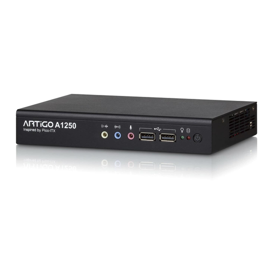
A1250 User Manual User Manual ARTiGO ARTiGO A1250 A1250 User Manual User Manual 1.4. ARTiGO-A1250 Layout Figure Figure 3 3 3 3 : : : : Front Panel l Front Panel layout ayout Figure Figure Front Panel l Front Panel l... -
Page 18: External I/O Pin Descriptions And Functionality
Functionality and Functionality and Functionality and Functionality The VIA ARTiGO-A1250 has a wide selection of interfaces located on the front and rear panels as part of the external I/O. 2.1. Front Panel 2.1.1. Power Button The ARTiGO-1250 comes with a Power On/Off button, that supports Soft Power-On/Off (Instant Off or 4 second delay) and Suspend. -
Page 19: Usb 2.0 Port
User Manual User Manual 2.1.3. USB 2.0 Port The ARTiGO-A1250 provides two USB 2.0 ports in the front panel for Plug & Play and hot swapping access to external devices. The USB interface complies with USB UHCI, Rev. 2.0. Figure... -
Page 20: Audio Jacks
User Manual User Manual 2.1.4. Audio Jacks The ARTiGO-A1250 offers High Definition Audio through three 3.5 mm TRS jack connectors: Line-in, Line-out and Mic-in. The Line-In jack is for connecting an external audio devices such as CD player, tape player and etc. The Line-out jack is for connecting to external speakers or headphones. -
Page 21: Rear Panel
A1250 A1250 User Manual User Manual 2.2. Rear Panel 2.2.1. Power Input (DC-In) Jack The ARTiGO-A1250 comes with a DC power input jack on the real panel that carries 12V . External power input. Figure Figure Figure Figure 9 9 9 9 : Power... -
Page 22: Lan Port: Gigabit Ethernet
User Manual 2.2.2. LAN Port: Gigabit Ethernet The ARTiGO-A1250 system is equipped with one Gigabit Ethernet port (LAN1) on rear panel. The port is fully compliant with IEEE 802.3 (10BASE-T), 802.3u (100BASE-TX), and 802.3ab (1000BASE-T) standards. The pinout of the LAN1... -
Page 23: Usb 3.0 Port
ARTiGO- - - - A1250 ARTiGO A1250 User Manual User Manual ARTiGO ARTiGO A1250 A1250 User Manual User Manual 2.2.3. USB 3.0 Port The ARTiGO-1250 is equipped with two USB 3.0 ports, also known as SuperSpeed USB. The USB 3.0 port has a maximum data transfer rate up to 5 Gbps and offers a backwards compatible with previous USB 2.0 specifications. -
Page 24: Vga Connector
User Manual 2.2.4. VGA Connector The ARTiGO-A1250 provides a high resolution VGA interface through a 15-pin D-sub female connector to support analog VGA monitors. It supports up to 2560 x 1600 @ 60Hz resolution and up to 512 MB shared memory. -
Page 25: Mini Hdmi ® Port
ARTiGO- - - - A1250 ARTiGO A1250 User Manual User Manual ARTiGO ARTiGO A1250 A1250 User Manual User Manual ® 2.2.5. Mini HDMI Port ® ® The integrated 19-pin HDMI port uses an HDMI Type C connector as ® ® defined in the HDMI specification. -
Page 26: Hardware Installation Hardware Installation
ARTiGO- - - - A1250 ARTiGO A1250 User Manual User Manual ARTiGO ARTiGO A1250 A1250 User Manual User Manual 3. 3. 3. 3. Hardware Installation Hardware Installation Hardware Installation Hardware Installation This chapter provides you with information about hardware installation procedures. - Page 27 ARTiGO- - - - A1250 ARTiGO A1250 User Manual User Manual ARTiGO ARTiGO A1250 A1250 User Manual User Manual Step 2 Remove the two screws from the memory access cover then gently lift up the cover. Flip over the memory access cover and remove the memory thermal pad plastic cover.
- Page 28 ARTiGO- - - - A1250 ARTiGO A1250 User Manual User Manual ARTiGO ARTiGO A1250 A1250 User Manual User Manual Step 4 Reinstall the memory access cover and secure it with two screws.
-
Page 29: Installing 2.5 Inch Sata Hard Disk Drive
ARTiGO- - - - A1250 ARTiGO A1250 User Manual User Manual ARTiGO ARTiGO A1250 A1250 User Manual User Manual 3.2. Installing 2.5 inch SATA Hard Disk Drive Step 1 Remove the six screws of the top cover from both sides and bottom side of the chassis. - Page 30 ARTiGO- - - - A1250 ARTiGO A1250 User Manual User Manual ARTiGO ARTiGO A1250 A1250 User Manual User Manual Step 3 Pull out the hard disk bracket tray. Then remove the cover plastic of the hard disk thermal pad. Step 4 Flip over the hard disk drive and install it to the hard disk bracket tray over the thermal pad.
- Page 31 ARTiGO- - - - A1250 ARTiGO A1250 User Manual User Manual ARTiGO ARTiGO A1250 A1250 User Manual User Manual Step 5 Gently slide back the bracket tray with the 2.5 inch hard disk. Ensure that no wiring has been pinched while reinstalling the bracket tray. Secure the bracket tray with screw.
-
Page 32: Installing The Wlan Kit
ARTiGO- - - - A1250 ARTiGO A1250 User Manual User Manual ARTiGO ARTiGO A1250 A1250 User Manual User Manual 3.3. Installing the WLAN kit Step 1 Remove the antenna WLAN hole cover at the back panel of ARTiGO-1250. Install the WLAN module and secure it with two screws. Step 2 Remove the P910-D bridge board connector. - Page 33 ARTiGO- - - - A1250 ARTiGO A1250 User Manual User Manual ARTiGO ARTiGO A1250 A1250 User Manual User Manual Step 3 Attach the WLAN cable to the WLAN module. Then attach the other end of the cable to the P910-C daughter board. The WLAN cable must be layout underneath the P910-D bridge board connector before reinstalling the P910-D bridge board connector.
- Page 34 ARTiGO- - - - A1250 ARTiGO A1250 User Manual User Manual ARTiGO ARTiGO A1250 A1250 User Manual User Manual Step 4 Insert the WLAN port connector into the antenna hole from the inside of the chassis. Insert the washer, fasten it with the nut and install the external antenna. Gently connect the mini coaxial cable of the WLAN port connector to the mini RF connector on the WLAN module.
-
Page 35: Installing The Power Dc Jack Strap Holder
ARTiGO- - - - A1250 ARTiGO A1250 User Manual User Manual ARTiGO ARTiGO A1250 A1250 User Manual User Manual 3.4. Installing the Power DC Jack Strap Holder Step 1 Prepare the DC jack strap holder. The DC jack strap holder consists of two parts: Slide strap tie and jack holder. - Page 36 ARTiGO- - - - A1250 ARTiGO A1250 User Manual User Manual ARTiGO ARTiGO A1250 A1250 User Manual User Manual Step 3 Insert the strap cable tie into the hole. Ensure the strap cable tie is fully inserted in vertical position and the slide rails are facing the left side as indicated in the figure.
- Page 37 ARTiGO- - - - A1250 ARTiGO A1250 User Manual User Manual ARTiGO ARTiGO A1250 A1250 User Manual User Manual Step 5 Insert the slide strap tie into the side of the jack. Step 6 Slide in deeply the jack holder until the power DC jack reaches the DC-in power port.
-
Page 38: Bios Setup Utility
ARTiGO- - - - A1250 ARTiGO A1250 User Manual User Manual ARTiGO ARTiGO A1250 A1250 User Manual User Manual 4. 4. 4. 4. BIOS Setup Utility BIOS Setup Utility BIOS Setup Utility BIOS Setup Utility 4.1. Entering the BIOS Setup Utility Power on the computer and press Delete Delete Delete during the beginning of the boot... -
Page 39: Getting Help
ARTiGO- - - - A1250 ARTiGO A1250 User Manual User Manual ARTiGO ARTiGO A1250 A1250 User Manual User Manual 4.3. Getting Help The BIOS Setup Utility provides a “General Help General Help General Help General Help” screen. This screen can be accessed at any time by pressing F1 F1 F1 F1. -
Page 40: System Overview
ARTiGO- - - - A1250 ARTiGO A1250 User Manual User Manual ARTiGO ARTiGO A1250 A1250 User Manual User Manual 4.4. System Overview The System Overview screen is the default screen that is shown when the BIOS Setup Utility is launched. This screen can be accessed by traversing the navigation bar to the “Main”... -
Page 41: System Date
ARTiGO- - - - A1250 ARTiGO A1250 User Manual User Manual ARTiGO ARTiGO A1250 A1250 User Manual User Manual 4.4.4. System Date This section shows the current system date. Press Tab Tab to traverse right and Shift+Tab Shift+Tab Shift+Tab Shift+Tab to traverse left through the month, day, and year segments. The + + + + and - - - - keys on the number pad can be used to change the values. -
Page 42: Advanced Settings
ARTiGO- - - - A1250 ARTiGO A1250 User Manual User Manual ARTiGO ARTiGO A1250 A1250 User Manual User Manual 4.5. Advanced Settings The Advanced Settings screen shows a list of categories that can provide access to a sub-screen. Sub-screen links can be identified by the preceding right-facing arrowhead. -
Page 43: Acpi Settings
ARTiGO- - - - A1250 ARTiGO A1250 User Manual User Manual ARTiGO ARTiGO A1250 A1250 User Manual User Manual 4.5.1. ACPI Settings ACPI grants the operating system direct control over system power management. The ACPI Configuration screen can be used to set a number of power management related functions. -
Page 44: S5 Rtc Wake Settings
ARTiGO- - - - A1250 ARTiGO A1250 User Manual User Manual ARTiGO ARTiGO A1250 A1250 User Manual User Manual 4.5.2. S5 RTC Wake Settings Figure Figure Figure Figure 17 17 17 17: Illustration of the : Illustration of the : Illustration of the : Illustration of the S5 RTC S5 RTC S5 RTC... -
Page 45: Cpu Configuration
ARTiGO- - - - A1250 ARTiGO A1250 User Manual User Manual ARTiGO ARTiGO A1250 A1250 User Manual User Manual 4.5.3. CPU Configuration The CPU Configuration screen shows detailed information about the built-in processor. In addition to the processor information, the thermal controls can be set. -
Page 46: Sata Configuration
ARTiGO- - - - A1250 ARTiGO A1250 User Manual User Manual ARTiGO ARTiGO A1250 A1250 User Manual User Manual 4.5.4. SATA Configuration The SATA Configuration screen allows the user to view and configure the settings of the SATA configuration settings. Figure Figure 19 19: Illustration of SATA Configuration screen... -
Page 47: Pc Health Status
ARTiGO- - - - A1250 ARTiGO A1250 User Manual User Manual ARTiGO ARTiGO A1250 A1250 User Manual User Manual 4.5.5. PC Health Status The PC Health Status screen has no editable fields. The system temperature is taken from an optional sensor that is connected to the J5 pin header. Fi Fi Fi Figure gure gure... -
Page 48: Clock Generator Configuration
ARTiGO- - - - A1250 ARTiGO A1250 User Manual User Manual ARTiGO ARTiGO A1250 A1250 User Manual User Manual 4.5.6. Clock Generator Configuration The Clock Generator Configuration screen enables access to the Spread Spectrum Setting feature. Figure Figure Figure Figure 21 21 21 21: Illustration of : Illustration of... -
Page 49: Onboard Device Configuration
ARTiGO- - - - A1250 ARTiGO A1250 User Manual User Manual ARTiGO ARTiGO A1250 A1250 User Manual User Manual 4.5.7. OnBoard Device Configuration The OnBoard Device Configuration screen has the following features. Figure Figure 22 22: Illustration of OnBoard Device Configuration screen : Illustration of OnBoard Device Configuration screen Figure Figure... - Page 50 ARTiGO- - - - A1250 ARTiGO A1250 User Manual User Manual ARTiGO ARTiGO A1250 A1250 User Manual User Manual 4.5.7.4. 4.5.7.4. 4.5.7.4. 4.5.7.4. Eup/Erp Lot6 Support Eup/Erp Lot6 Support Eup/Erp Lot6 Support Eup/Erp Lot6 Support The EuP/ErP Lot6 Support feature enables the BIOS to reduce the power draw to less than 1W when the system is in standby mode.
-
Page 51: Chipset Settings
ARTiGO- - - - A1250 ARTiGO A1250 User Manual User Manual ARTiGO ARTiGO A1250 A1250 User Manual User Manual 4.6. Chipset Settings The Chipset Settings screen shows a list of categories that can provide access to a sub-screen. Sub-screen links can be identified by the preceding right- facing arrowhead. -
Page 52: Dram Configuration
ARTiGO- - - - A1250 ARTiGO A1250 User Manual User Manual ARTiGO ARTiGO A1250 A1250 User Manual User Manual 4.6.1. DRAM Configuration The DRAM Configuration screen has two features for controlling the system DRAM. All other DRAM features are automated and cannot be accessed. Figure Figure Figure... - Page 53 ARTiGO- - - - A1250 ARTiGO A1250 User Manual User Manual ARTiGO ARTiGO A1250 A1250 User Manual User Manual 5 5 5 5 66 66 MHz 66 66 The 566 MHz option forces the BIOS to be fixed at 1132 MHz for DDR3 memory modules.
- Page 54 ARTiGO- - - - A1250 ARTiGO A1250 User Manual User Manual ARTiGO ARTiGO A1250 A1250 User Manual User Manual 4.6.1.2. 4.6.1.2. 4.6.1.2. 4.6.1.2. VGA Share Memory (Frame Buffer) VGA Share Memory (Frame Buffer) VGA Share Memory (Frame Buffer) VGA Share Memory (Frame Buffer) The VGA Share Memory feature enables the user to choose the amount of the system memory to reserve for use by the integrated graphics controller.
-
Page 55: Video Configuration
ARTiGO- - - - A1250 ARTiGO A1250 User Manual User Manual ARTiGO ARTiGO A1250 A1250 User Manual User Manual 4.6.2. Video Configuration The Video Configuration screen has features for controlling the integrated graphics controller in the VX11H chipset. Figure Figure Figure Figure 25 25 25... -
Page 56: Pmu_Acpi Configuration
ARTiGO- - - - A1250 ARTiGO A1250 User Manual User Manual ARTiGO ARTiGO A1250 A1250 User Manual User Manual 4.6.3. PMU_ACPI Configuration The PMU_ACPI Configuration screen can be used to set a number of power management related functions. Figure Figure Figure Figure 26 26 26... - Page 57 ARTiGO- - - - A1250 ARTiGO A1250 User Manual User Manual ARTiGO ARTiGO A1250 A1250 User Manual User Manual 4.6.3.1.1. 4.6.3.1.1. 4.6.3.1.1. 4.6.3.1.1. AC Loss Auto AC Loss Auto AC Loss Auto AC Loss Auto- - - - restart restart restart restart AC Loss Auto-restart defines how the system will respond after AC power has...
-
Page 58: Others Configuration
ARTiGO- - - - A1250 ARTiGO A1250 User Manual User Manual ARTiGO ARTiGO A1250 A1250 User Manual User Manual 4.6.4. Others Configuration The Others Configuration screen can be used to set Watchdog Timer Configuration and Keyboard/Mouse Wakeup Configuration. Figure Figure 28 28: Illustration of Others Configuration screen : Illustration of Others Configuration screen Figure... -
Page 59: Boot Settings
ARTiGO- - - - A1250 ARTiGO A1250 User Manual User Manual ARTiGO ARTiGO A1250 A1250 User Manual User Manual 4.7. Boot Settings The Boot Settings screen has a single link that goes to the Boot Configuration Boot Configuration Boot Configuration Boot Configuration and Boot Boot Option... -
Page 60: Boot Option Priorities
ARTiGO- - - - A1250 ARTiGO A1250 User Manual User Manual ARTiGO ARTiGO A1250 A1250 User Manual User Manual 4.7.2. Boot Option Priorities The Boot Option Priorities screen lists all bootable devices. 4.7.2.1. 4.7.2.1. Launch PXE OpROM policy Launch PXE OpROM policy 4.7.2.1. -
Page 61: Save & Exit
ARTiGO- - - - A1250 ARTiGO A1250 User Manual User Manual ARTiGO ARTiGO A1250 A1250 User Manual User Manual 4.8. Save & Exit The Save & Exit Configuration screen has the following features: Figure Figure Figure Figure 30 30 30 30: Illustration of Save &... -
Page 62: Discard Changes And Reset
ARTiGO- - - - A1250 ARTiGO A1250 User Manual User Manual ARTiGO ARTiGO A1250 A1250 User Manual User Manual 4.8.4. Discard Changes and Reset This command reverts all changes to the settings that were in place when the BIOS Setup Utility was launched. The “F7” hotkey can also be used to trigger this command. -
Page 64: Driver Installation................................ Driver Installation Driver Installation Driver Installation 5.1. Microsoft Driver Support
For embedded operating systems, the related drivers can be found in the VIA Embedded website at www.viaembedded.com. 5.2. Linux Driver Support The VIA ARTiGO-A1250 mainboard is highly compatible with many Linux distributions. Support and drivers are provided through various methods including:... - Page 65 Taiwan Headquarters Europe 1F, 531 Zhong-Zheng Road 940 Mission Court In den Dauen 6 Xindian District, New Taipei City 231, Fremont, CA 94539 53117 Bonn Taiwan Germany TEL: 886.2.2218.5452 TEL: 1.510.683.3300 TEL: 49.228.688565.0 FAX: 886.2.2218.5453 FAX: 1.510.687.4654 FAX: 49.228.688565.19 Email: embedded@via.com.tw Email: embedded@viatech.com Email: embedded@via-tech.de China...
Need help?
Do you have a question about the ARTiGO-A1250 and is the answer not in the manual?
Questions and answers