Sign In
Upload
Manuals
Brands
VIA Technologies Manuals
Desktop
AMOS-820-6Q10A1
VIA Technologies AMOS-820-6Q10A1 Manuals
Manuals and User Guides for VIA Technologies AMOS-820-6Q10A1. We have
2
VIA Technologies AMOS-820-6Q10A1 manuals available for free PDF download: User Manual
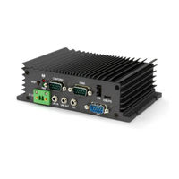
VIA Technologies AMOS-820-6Q10A1 User Manual (40 pages)
Fanless ultra-compact quad-core Edge Computing system ruggedized for extreme environments
Brand:
VIA Technologies
| Category:
Desktop
| Size: 6.37 MB
Table of Contents
Table of Contents
6
1 Product Overview
10
Key Features
10
High-Performance
10
Fanless, Ruggedized, Ultra-Compact and Space Saving
10
Stylish and Fully Sealed Design
10
Optimize Integration with Multiple I/O Access
10
Storage Expansion
10
Wide Range of Operating Temperature
11
Shock Resistant
11
Networking Option
11
Power over Ethernet (Optional)
11
Multiple Mounting Option
11
Embedded Operating System Ready
11
Product Specifications
12
Layout Diagram
15
Figure 1: Front Panel I/O Layout
15
Figure 2: Back Panel I/O Layout
15
Product Dimensions
16
Figure 3: Dimensions of the VIA AMOS-820 (Front View)
16
Figure 4: Dimensions of the VIA AMOS-820 (Top View)
16
Figure 5: Dimensions of the VIA AMOS-820 (Rear View)
16
2 External I/O Pin Descriptions and Functionality
17
DC-In Jack
17
Reset Button
17
Figure 6: DC-In Jack Diagram
17
Figure 7: Reset Button Diagram
17
Table 1: DC-In Jack Pinouts
17
LED Indicator
18
CAN/COM2 Port
18
Figure 8: LED Indicator Diagram
18
Figure 9: CAN/COM2 Port Diagram
18
Table 2: CAN/COM2 Port Pinouts
18
COM1 Port
19
Figure 10: COM1 Port Diagram
19
Table 3: COM1 Port Pinouts
19
USB 2.0 Port
20
Micro USB 2.0 OTG Port
20
Figure 11: USB 2.0 Port Diagram
20
Figure 12: Micro USB 2.0 OTG Port Diagram
20
Table 4: USB 2.0 Port Pinouts
20
Table 5: Micro USB 2.0 OTG Port Pinouts
20
Audio Jack
21
DIO Port
21
Figure 13: Audio Jack Receptacle Diagram
21
Figure 14: DIO Port Diagram
21
Table 6: Audio Jack Receptacle Pinouts
21
Table 7: DIO Port Pinouts
21
Micro SD/SPI Boot Switch
22
Gigabit Ethernet Port
22
Figure 15: Micro SD/SPI Boot Switch Diagram
22
Figure 16: Gigabit Ethernet Port Diagram
22
Table 8: Gigabit Ethernet Port Pinouts
22
Table 9: Gigabit Ethernet Port LED Color Definition
22
HDMI ® Port
23
Composite RCA Jack
23
Figure 17: HDMI ® Port Diagram
23
Figure 18: Composite RCA Jack Diagram
23
Table 10: HDMI ® Port Pinouts
23
3 Onboard I/O
24
Minipcie Slot
24
Micro SD Card Slot
24
Figure 19: Minipcie Slot Diagram
24
Figure 20: Micro SD Card Slot Diagram
24
4 Hardware Installation
25
Installing the Micro SD Card
25
Figure 21: Removing the Bottom Access Cover
25
Figure 22: Inserting the Micro SD Card
25
Installing the Rubber Feet
26
Figure 23: Installing the Rubber Feet
26
Mounting the VIA AMOS-820 System
27
Figure 24: Mounting the VIA AMOS-820 System
27
5 Software and Technical Supports
28
Android and Linux Support
28
Technical Supports and Assistance
28
Appendix A. Installing Wireless Accessories
29
Installing the VNT9271 USB Wi-Fi Dongle
29
Figure 25: Installing the VNT9271 Dongle
29
Figure 26: Removing the Bottom Access Cover
30
Figure 27: Removing the Screw and Nut from the EMIO-2531 Module
30
Figure 28: Installing the EMIO-2531 Module
31
Figure 29: Securing the EMIO-2531 Module
31
Figure 30: Removing the Screws of the Top Cover Chassis, and Front, Back and Bottom Panel Plates
32
Figure 31: Pulling out the Back Panel Plate, Top Cover Chassis, and Removing the Antenna Hole Cover
32
Figure 32: Installing Wi-Fi Antenna Cable and Antenna
33
Figure 33: Connecting the Wi-Fi Antenna Cable to the Micro-RF Connector on the EMIO-2531 Module
33
Figure 34: Reinstalling Bottom Access Cover
34
Figure 35: Removing the Bottom Access Cover
35
Figure 36: Removing the Screws of the Top Cover Chassis, and Front, Back and Bottom Panel Plates
35
Figure 37: Pulling out the Top Cover Chassis, Back Panel Plate, and Removing the Antenna Holes Cover
36
Figure 38: Installing the 3G and GPS Antenna Cables and Antennas
36
Figure 39: Inserting the 3G SIM Card
37
Figure 40: Connecting the GPS Antenna Cable to the Micro-RF Connector on the EMIO-2550
37
Figure 41: Installing the EMIO-2550 Module
38
Figure 42: Securing the EMIO-2550 Module
38
Figure 43: Connecting the 3G Antenna Cable to the Micro-RF Connecter on the EMIO-2550
39
Figure 44: Reinstalling the Bottom Access Cover
39
Advertisement
VIA Technologies AMOS-820-6Q10A1 User Manual (35 pages)
AMOS-820 series. Fanless ultra-compact quad- core ARM system ruggedized for extreme environments
Brand:
VIA Technologies
| Category:
Industrial PC
| Size: 1.95 MB
Table of Contents
Table of Contents
6
1 Product Overview
9
Key Features
9
ARM Based System
9
Fanless, Ruggedized, Ultra Compact and Space Saving
9
Stylish and Fully Sealed Design
9
Optimize Integration with Multiple I/O Access
9
Storage Expansion
9
Wide Range of Operating Temperature
9
Shock Resistant
10
Networking Option
10
Power over Ethernet (Optional)
10
Multiple Mounting Option
10
Embedded os Ready
10
Product Specifications
11
Layout Diagram
14
Figure 1: Front Panel I/O Layout
14
Figure 2: Back Panel I/O Layout
14
Product Dimensions
15
Figure 3: Dimensions of the AMOS-820 (Front View)
15
Figure 4: Dimensions of the AMOS-820 (Top View)
15
Figure 5: Dimensions of the AMOS-820 (Rear View)
15
2 External I/O Pin Descriptions and Functionality
16
DC-In Jack
16
Reset Button
16
Figure 6: DC-In Jack Diagram
16
Figure 7: Reset Button Diagram
16
Table 1: DC-In Jack Pinout
16
LED Indicator
17
CAN/COM2 Port
17
Figure 8: LED Indicator Diagram
17
Figure 9: CAN/COM2 Port Diagram
17
Table 2: CAN/COM2 Port Pinouts
17
COM1 Port
18
Figure 10: COM1 Port Diagram
18
Table 3: COM1 Port Pinouts
18
USB 2.0 Port
19
Micro USB 2.0 OTG Port
19
Figure 11: USB 2.0 Port Diagram
19
Figure 12: Micro USB 2.0 OTG Port Diagram
19
Table 4: USB 2.0 Port Pinouts
19
Table 5: Micro USB 2.0 OTG Port Pinouts
19
Audio Jack
20
DIO Port
20
Figure 13: Audio Jack Receptacle Diagram
20
Figure 14: DIO Port Diagram
20
Table 6: Audio Jack Receptacle Pinout
20
Table 7: DIO Port Pinouts
20
Micro SD/SPI Boot Select Switch
21
Gigabit Ethernet Port
21
Figure 15: Micro SD/SPI Boot Select Switch Diagram
21
Figure 16: Gigabit Ethernet Port Diagram
21
Table 8: Gigabit Ethernet Port Pinouts
21
Table 9: Gigabit Ethernet Port LED Color Definition
21
HDMI ® Port
22
RCA Jack
22
Figure 17: HDMI ® Port Diagram
22
Figure 18: RCA Jack Diagram
22
Table 10: HDMI ® Port Pinouts
22
Table 11: RCA Jack Pinout
22
3 Onboard I/O
23
Minipcie Slot
23
Micro SD Card Slot
23
Figure 19: Minipcie Slot Diagram
23
Figure 20: Micro SD Card Slot Diagram
24
4 Hardware Installation
25
Installing the Micro SD Card
25
Figure 21: Removing the Bottom Access Cover
25
Figure 22: Inserting the Micro SD Card
25
Installing the 3G/Wi-Fi Kit
27
Figure 23: Installing 3G/Wi-Fi Module
27
Figure 24: Securing 3G/Wi-Fi Module
27
Figure 25: Removing Front, Back and Bottom Plate Screws
28
Figure 26: Pulling out Back Panel Plate and Antenna Hole Cover
28
Figure 27: Installing 3G and Wi-Fi Antenna
29
Figure 28: Connecting Antenna Cable to the Micro-RF Connector
29
Figure 29: Reinstalling Bottom Access Cover
30
Installing the Rubber Feet
31
Figure 30: Installing the Rubber Feet
31
Mounting the AMOS-820 System
32
Figure 31: Mounting the AMOS-820 System
33
5 Software and Technical Supports
34
Android and Linux Support
34
Driver Installation
34
Technical Supports and Assistance
34
Advertisement
Related Products
VIA Technologies AMOS-820-2Q10A2
VIA Technologies AMOS-820-5Q10A1
VIA Technologies AMOS-820-1Q10A2
VIA Technologies AMOS-3001
VIA Technologies AMOS-3005
VIA Technologies ARTiGO-A1200
VIA Technologies ARTiGO-A1250
VIA Technologies ARTIGO A900
VIA Technologies ARTiGO A800
VIA Technologies ARTiGO A1250
VIA Technologies Categories
Motherboard
Computer Hardware
Desktop
Control Unit
Industrial PC
More VIA Technologies Manuals
Login
Sign In
OR
Sign in with Facebook
Sign in with Google
Upload manual
Upload from disk
Upload from URL