
Related Manuals for VIA Technologies AMOS-3001


Summary of Contents for VIA Technologies AMOS-3001
- Page 1 AMOS-3001 Fan-Less, Ultra Compact Embedded System Revision 1.07 107-06242013-1017...
-
Page 2: Regulatory Compliance
VIA Technologies, Inc. reserves the right the make changes to the products described in this manual at any time without prior notice. -
Page 3: Safety Precautions
Battery Recycling and Disposal Only use the appropriate battery specified for this product. Do not re-use, recharge, or reheat an old battery. Do not attempt to force open the battery. Do not discard used batteries with regular trash. Discard used batteries according to local regulations. Safety Precautions Always read the safety instructions carefully. -
Page 4: Box Contents
Box Contents 1 x AMOS-3001 1 x package of screws for mounting 1 x 2-pin Phoenix to DC Jack cable ® 1 x HDMI to DVI-D Adapter cable 1 x thermal pad for memory 1 x set of rubber washers for desktop mounting... -
Page 5: Table Of Contents
1 Product Overview....................1 Key Features......................2 Specifications ......................4 AMOS-3001 Dimensions ................. 6 AMOS-3001 I/O Layout (front)..............7 AMOS-3001 I/O Layout (rear) ..............7 Accessories......................8 AMOS-3001 storage expansion kit............8 SATA 2.5” hard disk ..................8 IDE Flash DOM....................9 SATA hard disk cables.................. - Page 6 Processor ......................42 System Memory.....................42 System Time ....................42 System Date ....................42 Advanced Settings ....................43 CPU Configuration ..................43 IDE Configuration ..................43 ACPI Configuration ..................43 APM Configuration ..................43 Spread Spectrum Configuration............43 USB Configuration..................43 CPU Configuration ...................44 CMPXCHG8B instruction support............44 IDE Configuration .....................45 Parallel ATA IDE Controller..............45 Hard Disk Write Protect ................45 IDE Detect Time Out (Sec)...............45 ATA(PI) 80Pin Cable Detection .............45...
- Page 7 Power Button Mode...................52 Suspend Power Saving Type..............52 Restore on AC / Power Loss ..............52 Manual Throttle Ratio.................52 System Thermal .....................53 Standby Time Out..................53 Suspend Time Out..................53 Hard Disk Time Out (Minute)..............53 Green PC Monitor Power State.............53 Video Power Down Mode..............53 Hard Disk Power Down Mode .............53 Display Activity....................53 Monitor IRQ3~15..................53...
- Page 8 Boot Device Priority..................59 Boot Settings Configuration.................60 Quick Boot.......................60 Display Logo....................60 AddOn ROM Display Mode..............60 Bootup Num-Lock ..................60 PS/2 Mouse Support...................60 Wait For ‘F1’ If Error..................60 Hit ‘DEL’ Message Display................60 Interrupt 19 Capture...................61 Boot Device Priority ..................62 1st Boot Device .....................62 Security Settings....................63 Change Supervisor Password ..............63 Change User Password ................63...
- Page 9 Power Button....................70 Power Input (DC-In) Port................70 LED Indicators (Power LED and HDD LED)........70 DIO Port......................70 Audio Port (Speaker-out and Mic-in)..........71 USB Ports ......................71 COM Ports......................71 VGA Port ......................72 ® HDMI Port .....................73 LAN Port ......................73...
-
Page 11: Product Overview
Product Overview... -
Page 12: Key Features
P820 The AMOS-3001 houses the EPIA-P720 or EPIA-P820 Pico-ITX form factor embedded board. With a maximum mounting height of only 45 mm, the AMOS-3001 can be used in space critical installation environments. Slim Slim, s , s , s , stylish, fully sealed... - Page 13 Networking options Networking options Networking options The AMOS-3001 can provides Gigabit Ethernet support for high speed data transmission. And through the storage expansion kit, the optional wireless networking module can provide the AMOS- 3001 with the freedom of WiFi access.
-
Page 14: Specifications
PECIFICATIONS CPU options VIA Nano 1.2 GHz processor • NanoBGA2 package • 800 MHz Front Side Bus VIA Eden ULV 1.0 GHz processor • NanoBGA2 package • 400 MHz Front Side Bus VIA VX855 Unified Digital Media IGP chipset Chipset Supports one 200-pin DDR2 533/667/800 MHz Memory SDRAM SODIMM... - Page 15 System and Watchdog Timer • programmable system reset 1~255 seconds Power Management ACPI 3.0 Compliant Output Rating: Power supply • Maximum: 21.60 W • Typical: 19.14 W Fuse Rating: • 7 A @ 125 V Input Voltage: • 12 VDC Typical: •...
-
Page 16: Amos-3001 Dimensions
AMOS-3001 D IMENSIONS... -
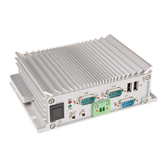
Page 17: Amos-3001 I/O Layout (Front)
AMOS-3001 I/O L AYOUT FRONT AMOS-3001 I/O L AYOUT REAR... -
Page 18: Accessories
CCESSORIES AMOS-3001 storage expansion kit SATA 2.5” hard disk... -
Page 19: Ide Flash Dom
IDE Flash DOM SATA hard disk cables... -
Page 20: Wlan Kit
WLAN kit VESA mounting kit... -
Page 21: Basic Installation
Basic installation... -
Page 22: Installing The Memory
NSTALLING THE MEMORY Step 1 Step 1 Step 1 Step 1 Locate memory access cover on the bottom of the AMOS-3001 and remove the two screws as indicated in the figure below. Step 2 Step 2 Step 2 Step 2... - Page 23 Step 3 Step 3 Step 3 Step 3 Insert the memory module into the SODIMM socket at the 45 degree angle. Then push down until the memory module snaps into place. The SODIMM socket has two locking mechanisms that will click once the memory module has been fully inserted. Step 4 Step 4 Step 4...
- Page 24 Step 5 Step 5 Step 5 Step 5 Reinstall the memory access cover. Secure the memory access cover in place with the two screws.
-
Page 25: Installing The Ide Flash Dom
IDE F NSTALLING THE LASH Step 1 Step 1 Step 1 Step 1 Locate the IDE Flash DOM access cover on the side of the AMOS- 3001 and remove the two screws as indicated in the figure below. Step 2 Step 2 Step 2 Step 2... - Page 26 Step 3 Step 3 Step 3 Step 3 Pin 1 of the IDE Flash DOM connector is on the left side of the DOM access port. Ensure that the pins are correctly aligned with the IDE Flash DOM before attempting to insert the IDE Flash DOM. Step 4 Step 4 Step 4...
-
Page 27: Preparing Cables And Connectors
REPARING ABLES AND ONNECTORS Opening the Chassis Step 1 Step 1 Step 1 Step 1 Remove the four corner screws from the bottom of the AMOS- 3001. Step Step Step Step 2 2 2 2 Flip over the chassis and unscrew the four chassis screws from ®... - Page 28 Step Step Step Step 3 3 3 3 Then pull the rear face plate and gently slide the top cover backward and lift off the top cover.
-
Page 29: Connecting The Dio Cable
Connecting the DIO Cable Step 1 Step 1 Step 1 Step 1 Locate the DIO pin header onto the EPIA-P720 mainboard. Step 2 Step 2 Step 2 Step 2 Then insert the DIO cable connector onto the pin header. -
Page 30: Connecting The Audio Cable
Connecting the Audio Cable Step 1 Step 1 Step 1 Step 1 Locate the audio pin header on the P720-B daughterboard. Step 2 Step 2 Step 2 Step 2 Gently insert the audio cable onto the pin header. -
Page 31: Connecting The Power Switch Cable
Connecting the Power Switch Cable Step 1 Step 1 Step 1 Step 1 Locate the power switch pin head on the EPIA-P720-B daughterboard. Step 2 Step 2 Step 2 Step 2 Then gently insert the power switch cable onto the pin header. The red wire should be on pin 1 of the pin header. -
Page 32: Connecting The 10-Pin Uart Cable
Connecting the 10-pin UART Cable Step 1 Step 1 Step 1 Step 1 Locate the 10-pin UART connector ports on the P720-B daughterboard and mainboard. Step 2 Step 2 Step 2 Step 2 Follow the proper orientation of the connector ports. Then gently connect the UART cable to the daughterboard and the mainboard. -
Page 33: Connecting The 12-Pin Uart Cable
Connecting the 12-pin UART Cable Step 1 Step 1 Step 1 Step 1 Locate the 12-pin UART connector ports on the P720-B daughterboard and mainboard. Step 2 Step 2 Step 2 Step 2 Follow the proper orientation of the connector ports. Then gently connect the UART cable to the daughterboard and the mainboard. -
Page 34: Connecting The Power Cable
Connecting the Power Cable Step 1 Step 1 Step 1 Step 1 Locate the power connector and then insert the power cable into the connector. -
Page 35: Installing The Expansion Kit
Installing the expansion kit... -
Page 36: Preparing The Amos-3001
AMOS-3001 REPARING THE Before installing the storage expansion kit, the AMOS-3001 needs to be prepared. Step 1 Step 1 Step 1 Step 1 Remove the memory access cover. Step 2 Step 2 Step 2 Step 2 Remove the cable hole cover on the memory access cover. File... - Page 37 Step Step Step Step 3 3 3 3 Thread the required cables for the SATA storage device through the cable hole. To install a SATA 2.5” hard disk, a SATA power cable and a SATA data cable are required. If installing the WLAN kit the WLAN USB cable also needs to be threaded through the cable hole.
- Page 38 Step 5 Step 5 Step 5 Step 5 Carefully unscrew and remove the P720-B daughterboard. Lift the board off vertically until it has been disconnected from all pins, otherwise the pin header may be bent. Step Step 6 6 6 6 Step Step Wrap the SATA cable and SATA power cable into the available...
- Page 39 Step Step Step Step 7 7 7 7 First insert the SATA data and SATA power cable through the cable hole in the bottom plate. Ensure that the cable is placed in the spacing on the daughterboard. Then gently insert the SATA data and power cable onto the board connector.
-
Page 40: Installing The Sata 2.5" Hard Disk
SATA 2.5” NSTALLING THE HARD DISK Step 1 Step 1 Step 1 Step 1 Remove the SATA 2.5” hard disk mounting bracket. Step 2 Step 2 Step 2 Step 2 Align the mounting holes on the SATA 2.5” hard disk with the mounting holes on the hard disk mounting bracket. - Page 41 Step 3 Step 3 Step 3 Step 3 Secure the hard disk in place with four hard disk screws. Then connect the SATA power and data cables to the hard disk. Step 4 Step 4 Step 4 Step 4 Align the mounting bracket with the mounting holes on the storage chassis.
-
Page 42: Installing The Wlan Kit
WLAN NSTALLING THE Step 1 Step 1 Step 1 Step 1 Locate the WLAN antenna hole and install the WLAN antenna. Step Step Step Step 2 2 2 2 Mount the WLAN module on the bottom side of storage chassis cover with two screws. - Page 43 Step Step Step Step 3 3 3 3 Flip the cover plate over and connect the WLAN USB cable to the mini USB connector on the WLAN module. Step 4 Step 4 Step 4 Step 4 Connect the WLAN antenna cable to the mini RF connector on the WLAN module.
- Page 44 Step 6 Step 6 First insert the WLAN cable through the cable hole in the bottom plate of AMOS-3001 then gently connect the WLAN cable to the WLAN pin header on the daughterboard. Note: When the WLAN cable is installed, USB port 5 will be disabled.
-
Page 45: Mounting The Storage Chassis
Step 1 First remove the cover of the IDE Flash DOM slot. Then position the AMOS-3001 directly above the storage chassis with the bottom side facing down. Align the mounting holes of the AMOS-3001 with those of the storage chassis. - Page 46 Insert the storage chassis cover in between the AMOS-3001 and storage chassis. Step Step 3 3 3 3 Step Step Secure first the storage chassis to the AMOS-3001 with four screws. Then replace the IDE Flash DOM cover with two screws.
-
Page 47: Installing The Mounting Plate
NSTALLING THE MOUNTING PLATE Step Step 1 1 1 1 Step Step Fasten the VESA mounting plate to a VESA mountable device with four screws. Step 2 Step 2 Step 2 Step 2 Position the mounting brackets on both sides of the storage expansion kit with four screws. - Page 48 Step 3 Step 3 Step 3 Step 3 Secure the mounting brackets to the VESA mounting plate with four screws. With Storage Chassis With Storage Chassis With Storage Chassis With Storage Chassis Without Storage Chassis Without Storage Chassis Without Storage Chassis Without Storage Chassis...
-
Page 49: Bios Setup
BIOS Setup This chapter gives a detailed explanation of the BIOS setup functions. -
Page 50: Entering The Bios Setup Menu
BIOS S NTERING THE ETUP Power on the computer and press <Delete Delete> during the beginning Delete Delete of the boot sequence to enter the BIOS setup menu. If you missed the BIOS setup entry point, restart the system and try again. ONTROL Keys Description... -
Page 51: Getting Help
ETTING The BIOS setup program provides a “General Help General Help” screen. You General Help General Help can display this screen from any menu/sub-menu by pressing <F1 F1>. The help screen displays the keys for using and navigating F1 F1 the BIOS setup. -
Page 52: Main Menu
AMIBIOS BIOS version number and related information. Processor CPU information. System Memory Memory size. System Time Use the key “+” or “-” to configure system time. The time format is [Hour : Minute : Second]. System Date Use the key “+” or “-” to configure system Date. The date format is [Day, Month, Date, Year]. -
Page 53: Advanced Settings
DVANCED ETTINGS CPU Configuration IDE Configuration ACPI Configuration APM Configuration Spread Spectrum Configuration USB Configuration... -
Page 54: Cpu Configuration
CPU C ONFIGURATION CMPXCHG8B instruction support Settings: [Enabled, Disabled]... -
Page 55: Ide Configuration
IDE C ONFIGURATION Parallel ATA IDE Controller Settings: [Disabled, Primary] Hard Disk Write Protect Settings: [Disabled, Enabled] IDE Detect Time Out (Sec) Settings: [0, 5, 10, 15, 20, 25, 30, 35] ATA(PI) 80Pin Cable Detection Settings: [Host & Device, Host, Device]... -
Page 56: Ide Drives
IDE D RIVES PATA Device SATA Device Type Settings: [Not Installed, Auto, CD/DVD, ARMD] LBA/Large Mode Settings: [Disabled, Auto]... -
Page 57: Block (Multi-Sector Transfer)
Block (Multi-Sector Transfer) Settings: [Disabled, Auto] PIO Mode Settings: [Auto, 0, 1, 2, 3, 4] DMA Mode Settings: [Auto] S.M.A.R.T. Self Monitoring Analysis and Reporting Technology, a monitoring system for hard disks. Settings: [Auto, Disabled, Enabled] 32Bit Data Transfer Settings: [Enabled, Disabled]... -
Page 58: Acpi Settings
ACPI S ETTINGS General ACPI Configuration Advanced ACPI Configuration Chipset ACPI Configuration... -
Page 59: General Acpi Configuration
ACPI C ENERAL ONFIGURATION Suspend Mode Select the ACPI state used for system suspend. Settings Description S1(POS) S1/Power On Suspend (POS) is a low power state. In this state, no system context (CPU or chipset) is lost and hardware maintains all system contexts S3(STR) S3/Suspend To RAM (STR) is a power-down state. -
Page 60: Advanced Acpi Configuration
ACPI C DVANCED ONFIGURATION ACPI Version Features To enable RSDP pointers to 64-bit Fixed System Description Tables. Settings: [ACPI v1.0, ACPI v2.0, ACPI v3.0] ACPI APIC Support To include ACPI APIC table pointer to RSDT pointer list. Settings: [Enabled, Disabled] AMI OEMB Table To include OEMB table pointer to R(X)SDT pointer lists. -
Page 61: Chipset Acpi Configuration
ACPI C HIPSET ONFIGURATION USB Device Wakeup Function Settings: [Disabled, Enabled]... -
Page 62: Apm Configuration
APM C ONFIGURATION Power Management / APM Settings: [Disabled, Enabled] Power Button Mode Settings: [On/Off, Standby, Suspend] Suspend Power Saving Type Settings: [C3, S1] Restore on AC / Power Loss The field defines how the system will respond after an AC power loss during system operation. -
Page 63: System Thermal
System Thermal Settings: [Disabled, Enabled] Standby Time Out Settings: [Disabled, 1/2/4/8/10/20/30/40/50/60 minutes] Suspend Time Out Settings: [Disabled, 1/2/4/8/10/20/30/40/50/60 minutes] Hard Disk Time Out (Minute) Settings: [Disabled, 1/2/3/4/5/6/7/8/9/10/11/12/13/14/15 minutes] Green PC Monitor Power State Settings: [Standby, Suspend, Off] Video Power Down Mode Settings: [Disabled, Standby, Suspend] Hard Disk Power Down Mode Settings: [Disabled, Standby, Suspend]... -
Page 64: Resume On Pme
Resume On PME# Settings: [Disabled, Enabled] Resume On PS/2 KBC Settings: [Disabled, S3, S3/S4/S5] Wake-up Key Settings: [Any Key, Specific Key] Resume on PS/2 Mouse Enable any mouse activity to restore the system from the power saving mode to an active state. Settings: [Disabled, S3, S3/S4/S5] Resume on RTC Alarm Set a scheduled time and/or date to automatically power on the... -
Page 65: Spread Spectrum Configuration
PREAD PECTRUM ONFIGURATION Spread Spectrum Configuration Settings: [Disabled, 0.1%, 0.2%, 0.3%, 0.4%, 0.5%, 0.6%, 0.7%, 0.8%, 0.9%]... -
Page 66: Usb Configuration
USB C ONFIGURATION USB 1.1 Ports Configuration To enable USB 1.1 host controllers. Settings: [Disabled, USB 2 ports, USB 4 ports, USB 6 ports] USB 2.0 Ports Enable To enable USB 2.0 host controllers. Settings: [Disabled, Enabled] USB Device Mode Enable Settings: [Enabled, Disabled] Legacy USB Support To enable support for legacy USB. -
Page 67: Advanced Pci/Pnp Settings
PCI/P DVANCED ETTINGS Note: This section covers some very technical items and it is strongly recommended to leave the default settings as it is unless you are an experienced user. Clear NVRAM To clear NVRAM during system boot. Settings: [No, Yes] Plug &... -
Page 68: Pci Ide Busmaster
PCI IDE BusMaster Settings: [Disabled, Enabled] Off Board PCI/ISA IDE Card Settings: [Auto, PCI Slot1, PCI Slot2, PCI Slot3, PCI Slot4, PCI Slot5, PCI Slot6] IRQ3~15 Settings: [Available, Reserved] DMA Channel 0 Settings: [Available, Reserved] DMA Channel 1 Settings: [Available, Reserved] DMA Channel 3 Settings: [Available, Reserved] DMA Channel 5... -
Page 69: Boot Settings
ETTINGS Boot Settings Configuration Configuration settings during system boot. Boot Device Priority Specifies the boot device priority sequence. -
Page 70: Boot Settings Configuration
ETTINGS ONFIGURATION Quick Boot Settings: [Disabled, Enabled] Display Logo Settings: [Disabled, Enabled] AddOn ROM Display Mode Settings: [Force BIOS, Keep Current] Bootup Num-Lock To select power-on state for Num-Lock. Settings: [Off, On] PS/2 Mouse Support Settings: [Disabled, Enabled, Auto] Wait For ‘F1’ If Error Settings: [Disabled, Enabled] Hit ‘DEL’... -
Page 71: Interrupt 19 Capture
Interrupt 19 Capture Settings: [Disabled, Enabled]... -
Page 72: Boot Device Priority
EVICE RIORITY 1st Boot Device To specifies the boot sequence from the available devices. The available boot devices are detected dynamically according to real situation and variable options will be provided. Settings: [Network: VIA Networking Bootagent, Disabled]... -
Page 73: Security Settings
ECURITY ETTINGS Change Supervisor Password This option is for setting a password for entering BIOS Setup. When a password has been set, a password prompt will be displayed whenever BIOS Setup is run. This prevents an unauthorized person from changing any part of your system configuration. -
Page 74: Advanced Chipset Settings
DVANCED HIPSET ETTINGS Caution: The Advanced Chipset Features menu is used for optimizing the chipset functions. Do not change these settings unless you are familiar with the chipset. North Bridge VIA VX855 Configuration South Bridge VIA VX855 Configuration... -
Page 75: North Bridge Via Vx855 Configuration
VIA VX855 ORTH RIDGE ONFIGURATION Software Reset E2 Issue Settings: [Patch, Escape Patch] Change DCLK using RDCKM Settings: [Program, Escape Program] Dynamic CKE Settings: [Disabled, Enabled] NB Performance Register Settings: [Disabled, Enabled] NB Energy Saving Register Settings: [Disabled, Enabled]... -
Page 76: Onchip Vga Configuration
VGA C ONFIGURATION VGA Frame Buffer Size Settings: [64MB, 128MB, 256MB] CPU Direct Access Frame Buffer Settings: [Disabled, Enabled] Select Display Device Settings: [CRT, HDMI, CRT+HDMI] Panel Type Settings: [02] Dithering Settings: [Disabled, Enabled]... -
Page 77: South Bridge Via Vx855 Configuration
VIA VX855 OUTH RIDGE ONFIGURATION High Definition Audio Settings: [Disabled, Auto] Enable Embedded COM Settings: [Disabled, Enabled] PCI SLOT1 Control (GigaLan) Settings: [Disabled, Enabled] PCI Delay Transaction Settings: [Disabled, Enabled] WATCH-DOG Settings: [Disabled, Enabled]... -
Page 78: Exit Options
PTIONS Save Changes and Exit Exit system setup after saving the changes, or press “F10”. Discard Changes and Exit Exit system setup without saving any changes, or press “Esc”. Discard Changes Discard changes which have been done so far to any of the setup questions, or press “F7”. -
Page 79: A Front & Rear Panel Io Pin Descriptions
Front & Rear Panel IO Pin Descriptions... -
Page 80: Io Pin Description
HDD LED is for Flash Disk on Module (DOM) or hard disk and compact flash disk status, which flash in red color. DIO Port AMOS-3001 provides one D-sub 9-pin female connector, which offers Digital IO communication interface port. Signal GPIO1 GPI4... -
Page 81: Audio Port (Speaker-Out And Mic-In)
Phone Jack 3.5Ø 5P, 90 Degree, Female, SHIELDED USB Ports The AMOS-3001 provides four USB 2.0 ports; two in the front panel, and two in the rear panel, which gives complete Plug & Play and hot swapping external devices. The USB interface complies with USB UHCI, Rev. -
Page 82: Vga Port
RS-485 serial communication interface by setting up the selector switch (SW1). To select the RS-232/422/485 setting, remove the top cover chassis of AMOS-3001 to locate the selector switch on the P720-B daughterboard. The setting instruction to select RS-232/422/485 mode, please refer to the table below. -
Page 83: Hdmi ® Port
DDCSDA Hot Plug Detect LAN Port The AMOS-3001 is equipped with VIA VT6122 Gigabit LAN controller. The Ethernet port provides a standard RJ-45 jack connector with LED indicators to show its Active/Link status (Green LED) and Speed status (white LED). - Page 84 Taiwan Headquarters Europe 1F, 531 Zhong-zheng Road, In den Dauen 6 940 Mission Court Xindian District, New Taipei City 231, 53117 Bonn Fremont, CA 94539 Taiwan Germany TEL: 886.2.2218.5452 TEL: 1.510.683.3300 TEL: 49.228.688565.0 FAX: 886.2.2218.5453 FAX: 1.510.687.4654 FAX: 49.228.688565.19 Email: embedded@via.com.tw Email: embedded@viatech.com Email: embedded@via-tech.de China...
Need help?
Do you have a question about the AMOS-3001 and is the answer not in the manual?
Questions and answers