
Related Manuals for VIA Technologies ARTiGO-A1100


Summary of Contents for VIA Technologies ARTiGO-A1100
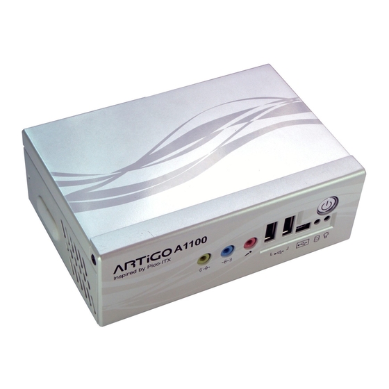
- Page 1 ARTiGO-A1100 Barebone System with EPIA-P820 Embedded Board Revision 1.04 104-11232010-1056...
-
Page 2: Copyright And Trademarks
However, VIA Technologies assumes no responsibility for the use or misuse of the information in this document and for any patent infringements that may arise from the use of this document. -
Page 3: Safety Precautions
Safety Precautions Do’s Always read the safety instructions carefully. Keep this User's Manual for future reference. All cautions and warnings on the equipment should be noted. Keep this equipment away from humidity. Lay this equipment on a reliable flat surface before setting it up. -
Page 4: Box Contents
Box Contents 1 x ARTiGO-A1100 system 1 x "Drivers and Utility" CD disc 1 x AC-to-DC adapter, DC 12V/5A, 60W 1 x Power cable, 180 cm, USA type... -
Page 5: Ordering Information
Ordering Information Model Number Description ATG-1100-1N12A1 VIA Nano™ 1.2GHz Processor based Embedded System, with 1 x VGA, 1 x HDMI, HD Audio (Line-in, Line-out and Mic- in), 1 x GigaLAN, 4 x USB 2.0 1 x USB device, DC-In 12V Optional Accessories Power Cord 99G33-02034C... -
Page 6: Table Of Contents
ABLE OF ONTENTS 1 Product Overview....................1 Key Features......................2 Specifications ......................4 ARTiGO-A1100 Dimensions................7 2 Front, Rear and Side I/O Pin Descriptions and Functionality..9 Front I/O Layout ....................10 Rear I/O Layout ....................10 Side I/O Layout....................10 I/O Pin Description ...................11 Power Button....................11... - Page 7 IDE Configuration ..................39 ACPI Configuration ..................39 APM Configuration ..................39 Spread Spectrum Configuration............39 USB Configuration..................39 CPU Configuration ...................40 CMPXCHG8B instruction support............40 Nano CPU Thermal Monitor Adjust............40 IDE Configuration .....................41 Parallel ATA IDE Controller..............41 Hard Disk Write Protect ................41 IDE Detect Time Out (Sec)...............41 ATA(PI) 80Pin Cable Detection .............41 IDE Drives ......................42 Primary IDE Master ..................42...
- Page 8 Standby Time Out..................49 Suspend Time Out..................49 Hard Disk Time Out (Minute)..............49 Green PC Monitor Power State.............49 Video Power Down Mode..............49 Hard Disk Power Down Mode .............49 Display Activity....................49 Monitor IRQ3~15..................49 Resume on Ring....................50 Resume on PME#..................50 Resume On PS/2 KBC ................50 Wake-up Key ....................50 Resume on PS/2 Mouse................50 Resume on RTC Alarm................50...
- Page 9 Hit ‘DEL’ Message Display................56 Interrupt 19 Capture...................57 Boot Device Priority ..................58 1st Boot Device .....................58 Security Settings....................59 Change Supervisor Password ..............59 Change User Password ................59 Boot Sector Virus Protection..............59 Advanced Chipset Settings................60 North Bridge VIA VX855 Configuration...........60 South Bridge VIA VX855 Configuration...........60 North Bridge VIA VX855 Configuration..........61 Software Reset E2 Issue................61 Change DCLK using RDCKM ..............61...
-
Page 10: Product Overview
Product Overview... -
Page 11: Key Features
Quick Data Transmission by USB d d d d evice port evice port evice port evice port The ARTiGO-A1100 comes with one USB device port that allows ARTiGO-A1100 as a USB Client device for user friendly and quick data transfer to another computer. Display Acceleration Display Acceleration Display Acceleration... - Page 12 Networking Networking support support support support The ARTiGO-A1100 is equipped with an RJ-45 port that supports Gigabit Ethernet. The ARTiGO-A1100 also has a WLAN module option that gives the ARTiGO-A1100 freedom of WiFi access. Embedded OS Embedded OS Embedded OS...
-
Page 13: Specifications
PECIFICATIONS Processor Core • VIA Nano 1.2 GHz processor Logic System • NanoBGA2 package • 800 MHz Front Side Bus speed • 1 MB L2 Cache memory System Chipset System Chipset System Chipset System Chipset • VIA VX855 Unified Digital Media IGP chipset BIOS BIOS BIOS... - Page 14 USB 2.0 U U U U SB SB SB SB 2.0 2.0 ports ports ports ports • Supports four USB 2.0 ports • Supports one USB device port Hard Disk Drive Hard Disk Drive Storage Hard Disk Drive Hard Disk Drive •...
- Page 15 Mechanical Construction Construction Construction Construction • Aluminum Chassis Housing Mounting Mounting Mounting Mounting •Optional Wall/VESA dual function mouting bracket Dimension (W x H x D) Dimension (W x H x D) Dimension (W x H x D) Dimension (W x H x D) •...
-
Page 16: Artigo-A1100 Dimensions
GO-A1100 D IMENSIONS... -
Page 18: Front, Rear And Side I/O Pin Descriptions And Functionality
Front, Rear and Side I/O Pin Descriptions and Functionality... -
Page 19: Front I/O Layout
I/O L RONT AYOUT I/O L AYOUT I/O L AYOUT... -
Page 20: I/O Pin Description
The HDD LED indicates the hard disk status and flashes in red. USB device port The ARTiGO-A1100 provides a USB device port in the front panel for quick data transfer to another computer. Signal +5VUSBD USBDP-... -
Page 21: Audio Ports (Line-Out, Line-In And Mic-In)
Audio Ports (Line-out, Line-in and Mic-in) The ARTiGO-A1100 offers High Definition Audio through three 3.5 mm TRS jack connectors: Line-out, Line-in and Mic-in. The Line-out jack is for connecting to external speakers or headphones. The Line-In jack is for connecting to an external audio device such as a CD player, tape player, etc. -
Page 22: Hdmi Port
DDCSDA Hot Plug Detect LAN Port The ARTiGO-A1100 is equipped with the VIA VT6122 Gigabit LAN controller. The Ethernet port provides a standard RJ-45 jack connector with LED indicators to show its Active/Link status (green LED) and Speed status (white LED). -
Page 24: Basic Installation
Basic installation... -
Page 25: Installing The Memory
Step 1 Step 1 Step 1 Step 1 Locate the memory access cover on the bottom side of the ARTiGO-A1100 and remove the screw. Step 2 Step 2 Step 2 Step 2 Remove the memory access cover as indicated in the figure below. - Page 26 Step 3 Step 3 Step 3 Step 3 Insert the memory module into the SODIMM socket at the 45 degree angle. Then push down until the memory module snaps into place. The SODIMM socket has two locking mechanisms that will click once the memory module has been fully inserted. Step 4 Step 4 Step 4...
- Page 27 Step Step Step Step 5 5 5 5 Reinstall the memory access cover and secure it with screw.
-
Page 28: Opening The Top Cover Chassis
Step 1 Step 1 Step 1 Step 1 Remove the screw of the top cover from the rear panel of the ARTiGO-A1100. Step 2 Step 2 Step 2 Step 2 Then gently slide the top cover backward and lift off the top cover... -
Page 29: Installing The Sata 2.5" Hard Disk
SATA 2.5” H NSTALLING THE Step 1 Step 1 Step 1 Step 1 Gently slide and remove the top cover backward and lift off the top cover. Step Step Step Step 2 2 2 2 On the bottom side of the top cover, remove the SATA 2.5” hard disk cover plate by unscrewing the four screws. - Page 30 Step Step Step Step 3 3 3 3 Attach the hard disk plate to the 2.5-inch SATA hard disk by aligning the mounting holes on the SATA 2.5” hard disk with the mounting holes on the hard disk cover plate. Then secure the hard disk in place with four screws.
- Page 31 Step Step Step Step 5 5 5 5 Reinstall the hard disk plate by aligning the cover plate with the mounting holes under the top cover and secure it with four screws. Step Step Step Step 6 6 6 6 Connect the SATA power and SATA data cables to the hard disk.
- Page 32 Step Step Step Step 7 7 7 7 Replace the top cover onto the ARTiGO-A1100.
-
Page 33: Installing The Sd Card Reader
SD C NSTALLING THE EADER Step 1 Step 1 Step 1 Step 1 Locate the mounting area of SD card reader. Remove the five screws in order to remove the front panel plate. Step 2 Step 2 Step 2 Step 2 Remove the fan duct as indicated in the figure below. - Page 34 Step 3 Step 3 Step 3 Step 3 Mount the SD card reader module (EMIO-5130) and secure it with two screws. Step 4 Step 4 Step 4 Step 4 Locate the SD card reader pin headers on the SD card reader module (EMIO-5130) and on the P820-B daughter card.
- Page 35 Step 5 Step 5 Step 5 Step 5 Gently connect the SD card reader cable to the pin header on the SD card reader module (EMIO-5130) and to the pin header on the P820-B daughter card.
- Page 36 Step 6 6 6 6 Properly route the SD card reader cable underneath the fan duct. Then reinstall the fan duct and front panel plate. Step Step Step Step 7 7 7 7 Replace the top cover of the ARTiGO-A1100.
-
Page 37: Installing The Wlan Kit
WLAN NSTALLING THE Step 1 Step 1 Step 1 Step 1 Remove the top cover and the front panel plate by unscrewing the five screws as indicated in the figure below. Step 2 Step 2 Step 2 Step 2 Remove the four screws indicated by the red arrows and carefully lift the fan duct off the board. - Page 38 Step 3 Step 3 Step 3 Step 3 Locate the WLAN pin header on the P820-B daughter card. Step 4 Step 4 Step 4 Step 4 Gently connect WLAN USB cable to the pin header on the P820-B daughter card.
- Page 39 Step 5 Step 5 Step 5 Step 5 First reinstall the fan duct, and connect the grounding cable to one of the screws of the fan duct as indicated in the figure below. Then attach the front panel plate and secure it with screws. Note: Make sure the WLAN USB cable is properly routed underneath the fan duct.
- Page 40 Then connect the WLAN antenna cable to the micro RF connector on the WLAN USB module (EMIO-1530) as indicated in the figure below. Step Step Step Step 9 9 9 9 Reinstall the top cover of the ARTiGO-A1100.
-
Page 41: Installing Vesa Mount Bracket
VESA M NSTALLING OUNT RACKET An optional VESA mount bracket kit is available for mounting the ARTiGO-A1100 behind the monitor. Step Step 1 1 1 1 Step Step Attach the VESA mount bracket to the back of the monitor as... - Page 42 Step Step 2 2 2 2 Step Step Place the ARTiGO-A1100 unit into the VESA mount bracket. Then connect all the necessary cables from the opening in the base of the bracket.
-
Page 44: Bios Setup
BIOS Setup This chapter gives a detailed explanation of the BIOS setup functions. -
Page 45: Entering The Bios Setup Menu
BIOS S NTERING THE ETUP Power on the computer and press <De Delete lete> during the beginning lete lete of the boot sequence to enter the BIOS setup menu. If you missed the BIOS setup entry point, restart the system and try again. ONTROL Keys Description... -
Page 46: Getting Help
ETTING The BIOS setup program provides a “General Help General Help” screen. You General Help General Help can display this screen from any menu/sub-menu by pressing <F1 F1>. The help screen displays the keys for using and navigating F1 F1 the BIOS setup. -
Page 47: Main Menu
AMIBIOS BIOS version number and related information. Processor CPU information. System Memory Memory size. System Time Use the key “+” or “-” to configure system time. The time format is [Hour : Minute : Second]. System Date Use the key “+” or “-” to configure system Date. The date format is [Day, Month, Date, Year]. -
Page 48: Advanced Settings
DVANCED ETTINGS CPU Configuration IDE Configuration ACPI Configuration APM Configuration Spread Spectrum Configuration USB Configuration... -
Page 49: Cpu Configuration
CPU C ONFIGURATION CMPXCHG8B instruction support Settings: [Enabled, Disabled] Nano CPU Thermal Monitor Adjust Settings: [Disabled, Thermal Monitor 1, Thermal Monitor 2, Thermal Monitor 3]... -
Page 50: Ide Configuration
IDE C ONFIGURATION Parallel ATA IDE Controller Settings: [Disabled, Primary] Hard Disk Write Protect Settings: [Disabled, Enabled] IDE Detect Time Out (Sec) Settings: [0, 5, 10, 15, 20, 25, 30, 35] ATA(PI) 80Pin Cable Detection Settings: [Host & Device, Host, Device]... -
Page 51: Ide Drives
IDE D RIVES Primary IDE Master Primary IDE Slave (SATA Device) -
Page 52: Type
Type Settings: [Not Installed, Auto, CD/DVD, ARMD] LBA/Large Mode Settings: [Disabled, Auto] Block (Multi-Sector Transfer) Settings: [Disabled, Auto] PIO Mode Settings: [Auto, 0, 1, 2, 3, 4] DMA Mode Settings: [Auto] S.M.A.R.T. Self Monitoring Analysis and Reporting Technology, a monitoring system for hard disks. -
Page 53: Acpi Settings
ACPI S ETTINGS General ACPI Configuration This menu contains ACPI (Advanced Configuration and Power Management Interface) options. Advanced ACPI Configuration Chipset ACPI Configuration... -
Page 54: General Acpi Configuration
ACPI C ENERAL ONFIGURATION Suspend Mode Select the ACPI state used for system suspend. Settings Description S1(POS) S1/Power On Suspend (POS) is a low power state. In this state, no system context (CPU or chipset) is lost and hardware maintains all system contexts S3(STR) S3/Suspend To RAM (STR) is a power-down state. -
Page 55: Advanced Acpi Configuration
ACPI C DVANCED ONFIGURATION ACPI Version Features To enable RSDP pointers to 64-bit Fixed System Description Tables. Settings: [ACPI v1.0, ACPI v2.0, ACPI v3.0] ACPI APIC Support To include ACPI APIC table pointer to RSDT pointer list. Settings: [Enabled, Disabled] AMI OEMB Table To include OEMB table pointer to R(X)SDT pointer lists. -
Page 56: Chipset Acpi Configuration
ACPI C HIPSET ONFIGURATION USB Device Wakeup Function Settings: [Disabled, Enabled]... -
Page 57: Apm Configuration
APM C ONFIGURATION Power Management / APM Settings: [Disabled, Enabled] Power Button Mode Settings: [On/Off, Standby, Suspend] Suspend Power Saving Type Settings: [C3, S1] Restore on AC / Power Loss The field defines how the system will respond after an AC power loss during system operation. -
Page 58: System Thermal
System Thermal Settings: [Disabled, Enabled] Standby Time Out Settings: [Disabled, 1/2/4/8/10/20/30/40/50/60 minutes] Suspend Time Out Settings: [Disabled, 1/2/4/8/10/20/30/40/50/60 minutes] Hard Disk Time Out (Minute) Settings: [Disabled, 1/2/3/4/5/6/7/8/9/10/11/12/13/14/15 minutes] Green PC Monitor Power State Settings: [Standby, Suspend, Off] Video Power Down Mode Settings: [Disabled, Standby, Suspend] Hard Disk Power Down Mode Settings: [Disabled, Standby, Suspend]... -
Page 59: Resume On Ring
Resume on Ring Settings: [Disabled, Enabled] Resume on PME# Settings: [Disabled, Enabled] Resume On PS/2 KBC Settings: [Disabled, S3, S3/S4/S5] Wake-up Key Settings: [Any Key, Specific Key] Resume on PS/2 Mouse Enable any mouse activity to restore the system from the power saving mode to an active state. -
Page 60: Spread Spectrum Configuration
PREAD PECTRUM ONFIGURATION Spread Spectrum Configuration Settings: [Disabled, 0.1%, 0.2%, 0.3%, 0.4%, 0.5%, 0.6%, 0.7%, 0.8%, 0.9%]... -
Page 61: Usb Configuration
USB C ONFIGURATION USB 1.1 Ports Configuration To enable USB 1.1 host controllers. Settings: [Disabled, USB 2 ports, USB 4 ports, USB 6 ports] USB 2.0 Ports Enable To enable USB 2.0 host controllers. Settings: [Disabled, Enabled] USB Device Mode Enable Settings: [Enabled, Disabled] Legacy USB Support To enable support for legacy USB. -
Page 62: Advanced Pci/Pnp Settings
PCI/P DVANCED ETTINGS Note: This section covers some very technical items and it is strongly recommended to leave the default settings as it is unless you are an experienced user. Clear NVRAM To clear NVRAM during system boot. Settings: [No, Yes] Plug &... -
Page 63: Pci Ide Busmaster
PCI IDE BusMaster Settings: [Disabled, Enabled] Off Board PCI/ISA IDE Card Settings: [Auto, PCI Slot1, PCI Slot2, PCI Slot3, PCI Slot4, PCI Slot5, PCI Slot6] IRQ3~15 Settings: [Available, Reserved] DMA Channel 0~7 Settings: [Available, Reserved] Reserved Memory Size To decide the size of memory block to reserve for legacy ISA devices. -
Page 64: Boot Settings
ETTINGS Boot Settings Configuration Configuration settings during system boot. Boot Device Priority Specifies the boot device priority sequence. -
Page 65: Boot Settings Configuration
ETTINGS ONFIGURATION Quick Boot Settings: [Disabled, Enabled] Display Logo Settings: [Disabled, Enabled] AddOn ROM Display Mode Settings: [Force BIOS, Keep Current] Bootup Num-Lock To select power-on state for Num-Lock. Settings: [Off, On] PS/2 Mouse Support Settings: [Disabled, Enabled, Auto] Wait For ‘F1’ If Error Settings: [Disabled, Enabled] Hit ‘DEL’... -
Page 66: Interrupt 19 Capture
Interrupt 19 Capture Settings: [Disabled, Enabled]... -
Page 67: Boot Device Priority
EVICE RIORITY 1st Boot Device To specifies the boot sequence from the available devices. The available boot devices are detected dynamically according to real situation and variable options will be provided. Settings: [Network: VIA Networking Bootagent, Disabled]... -
Page 68: Security Settings
ECURITY ETTINGS Change Supervisor Password This option is for setting a password for entering BIOS Setup. When a password has been set, a password prompt will be displayed whenever BIOS Setup is run. This prevents an unauthorized person from changing any part of your system configuration. -
Page 69: Advanced Chipset Settings
DVANCED HIPSET ETTINGS Caution: The Advanced Chipset Features menu is used for optimizing the chipset functions. Do not change these settings unless you are familiar with the chipset. North Bridge VIA VX855 Configuration South Bridge VIA VX855 Configuration... -
Page 70: North Bridge Via Vx855 Configuration
VIA VX855 ORTH RIDGE ONFIGURATION Software Reset E2 Issue Settings: [Patch, Escape Patch] Change DCLK using RDCKM Settings: [Program, Escape Program] Dynamic CKE Settings: [Disabled, Enabled] NB Performance Register Settings: [Disabled, Enabled] NB Energy Saving Register Settings: [Disabled, Enabled]... -
Page 71: Onchip Vga Configuration
VGA C ONFIGURATION VGA Frame Buffer Size Settings: [64MB, 128MB, 256MB] CPU Direct Access Frame Buffer Settings: [Disabled, Enabled] Select Display Device Settings: [CRT, LCD, HDMI, CRT+LCD, CRT+HDMI] Panel Type Settings: [02] Dithering Settings: [Disabled, Enabled] Backlight Control Settings: [0%, 25%, 50%, 75%, 100%]... -
Page 72: South Bridge Via Vx855 Configuration
VIA VX855 OUTH RIDGE ONFIGURATION Parallel Channel Enable Settings: [Enabled, Disabled] ISA Master Support Settings: [Support, Not Support] High Definition Audio Settings: [Disabled, Auto] Enable Embedded COM Settings: [Disabled, Enabled] PCI Debug Master Mode Settings: [Disabled, Enabled] SMBus Multi-Master Settings: [Disabled, Enabled] PCI VCC33 Leakage Patch Settings: [Disabled, Enabled]... -
Page 73: Pci Delay Transaction
PCI Delay Transaction Settings: [Disabled, Enabled] WATCH-DOG Settings: [Disabled, Enabled]... -
Page 74: Exit Options
PTIONS Save Changes and Exit Exit system setup after saving the changes, or press “F10”. Discard Changes and Exit Exit system setup without saving any changes, or press “Esc”. Discard Changes Discard changes which have been done so far to any of the setup questions, or press “F7”. -
Page 76: Driver Installation
Driver Installation This chapter gives you brief descriptions of each mainboard driver and application. You must install the VIA chipset drivers first before installing other drivers such as VGA drivers. The applications will only function correctly if the necessary drivers are already installed. -
Page 77: Driver Utilities
RIVER TILITIES Getting Started The ARTiGO-A1100 includes a driver CD that contains the drivers and software for enhancing the performance of the system. The drivers can also be downloaded from http://www.via.com.tw. Note: The driver utilities and software are updated from time to time. -
Page 78: Cd Content
CD C ONTENT VIA 4 in 1 Drivers VIA 4 in 1 Drivers VIA 4 in 1 Drivers VIA 4 in 1 Drivers Contains VIA ATAPI Vendor Support Driver (enables the performance enhancing bus mastering functions on ATA- capable Hard Disk Drives and ensures IDE device compatibility), AGP VxD Driver (provides service routines to your VGA driver and interface directly to hardware, providing fast graphical access), IRQ Routing Miniport...
Need help?
Do you have a question about the ARTiGO-A1100 and is the answer not in the manual?
Questions and answers