Table of Contents
Advertisement
Quick Links
z
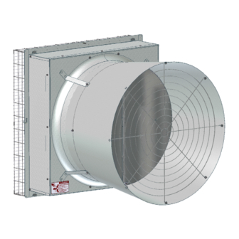
Fan and Fan Framing Dimensions
3
8
Item
1
Bottom Length
2
Vertical Dim. of Cone
3
Height (Outside of Flanges) 45-1/2" [115.57cm]
4
Rough Opening Width
5
Rough Opening Height
6
Minimum Spacing
7
Outside Diameter of Cone
8
Depth inside Building
Figure 1. Fan Dimensions
The Fan Inlet and exhaust must be kept clear of obstructions. Failure to keep the Fan airflow path
clear of obstructions could cause loss of Fan performance and Fan damage.
Do Not operate these Fans with a variable speed control device. Operating static pressure should be less
than 0.15 inches water column [37.4 pascal].
April 2018
36" Galvanized Belt Drive HYFLO
Installation and Operators Instruction Manual Fan
2
1
Description
Dimension
41-1/2'' [105.41cm]
1'' [2.54cm]
43" [109.22cm]
42-1/2 [107.95cm]
3-1/2" [8.89cm]
43-3/4" [111.13cm]
6-1/2" [16.51cm]
Part No. 53096-52
Planning the layout of the spacing between Fans is very
important. Spacing too close together will cause
interference between the discharge Cones. The Rough
Opening dimensions for Fans are shown above.
7
5
4
6
MV1747-017 04/03
®
Fans
MV2386E
Advertisement
Table of Contents

Related Manuals for Chore-Time Hyflo 53096-52


Summary of Contents for Chore-Time Hyflo 53096-52
- Page 1 ® 36" Galvanized Belt Drive HYFLO Fans Installation and Operators Instruction Manual Fan Part No. 53096-52 Fan and Fan Framing Dimensions Planning the layout of the spacing between Fans is very important. Spacing too close together will cause interference between the discharge Cones. The Rough Opening dimensions for Fans are shown above.
-
Page 2: Fan Assembly/Installation
Fan Assembly/Installation 36" Galvanized Belt Drive HYFLO® Fans Fan Assembly/Installation Screen Clips Set the Fan into the framed opening, but leave it hang out a few inches to allow for the insertion of four Screen Clips (Item 1, Figure 7). With the Screen Clips oriented with the tab lock as shown, push them into the slots in the Fan Housing Panels and rotate them forward until they lock into place as shown. -
Page 3: Attaching The Fan To The Wall
36" Galvanized Belt Drive HYFLO® Fans Fan Assembly/Installation Attaching the Fan to the Wall Slide the Fan assembly into the rough opening and starting with the side hole locations (Detail A), use 1/4 x 1-3/4" Lag Screws (Item 1, Figure 8), two Nylon Washers (Item 2), and a Screen Retainer (Item 3) to attach the Fan to the Wall as shown. -
Page 4: Belt Installation
Fan Assembly/Installation 36" Galvanized Belt Drive HYFLO® Fans Belt Installation Guide the Belt through the Opening in the Motor Support Bracket and loop it over the Motor Sheave. Guide the Belt around the Tensioner Sheave and push on it to get enough slack to put the Belt on the Driven Sheave as shown in Figure 10. - Page 5 Step 2: Step 3: Repeat Step 2 until all four Cone Panels Insert the Tabs of a second Cone Panel into the slots of the 1st are locked together. Panel and Lay it down locking the two Panels together. All Four Cone Panels Connected Step 5: Fasten the Cone Panels together with (4) 5/16"...
- Page 6 Fan Assembly/Installation 36" Galvanized Belt Drive HYFLO® Fans Installing Door Assembly Step 1: Remove Tape (Item 1) holding the Nylon Cable (Item 2) to the Door. Step 2: Line up the Four Holes in the Door Ring with the holes in the Cone and thread (4) 5/16 x 1-1/4"...
- Page 7 36" Galvanized Belt Drive HYFLO® Fans Fan Assembly/Installation Attaching the Door Stop Cable (Nylon Cable) and Grill. Step 1: Line up the Grill Eyehooks with the holes in the Cone. Thread the free end of the Nylon Cable (Item 2) through the bottom Grill Eyehook (Item 1) until it is flush with the Cone and secure it with a 5/16-18 Carriage Bolt (Item 3) and Flange Nut (Item 4) as shown.
- Page 8 Fan Assembly/Installation 36" Galvanized Belt Drive HYFLO® Fans Assembling the Cone to the Fan Use 5/16 x 5/8" Carriage Bolts and 5/16 Flange Nuts to attach the four Cone Brackets to the Fan Shroud as shown in Figure 15. Item Description Cone Bracket 5/16 x 5/8"...
- Page 9 36" Galvanized Belt Drive HYFLO® Fans Fan Assembly/Installation Door Spring Assembly Step 1: Step 2: On the Door Assembly, at the middle Hook the rounded ends of the Door of the Door Center Brace, attach the Springs onto the Spring Mounting Spring Mounting Bracket (Included Bracket.
- Page 10 Fan Assembly/Installation 36" Galvanized Belt Drive HYFLO® Fans Cone Drain Tabs The Fan Cone is designed with a C-Shaped Drain Tab located at the back of the Bottom Cone Panel. Use a screw driver to push the Drain Tab out as shown in Figure 18 below. Item Description Drain Tab...
- Page 11 36" Galvanized Belt Drive HYFLO® Fans Fan Assembly/Installation Assembling the Screen Keep Rotating Installing a Spring Install Spring at each Corner. per steps A-D below. 2. Install a spring (54480) in the 3. Rotate the Screen in the direction upper left corner following 1.
-
Page 12: Installing The Screen
Fan Assembly/Installation 36" Galvanized Belt Drive HYFLO® Fans Installing the Screen Step 1: Hang the Screen (Item 1) on the four Screen Clips (Item 2) and position so that Screen Wire is captured between 1/8" tall Tabs and Screen Retainers (Item 3). Step 2: Rotate the four Screen Retainers to capture the Screen. - Page 13 36" Galvanized Belt Drive HYFLO® Fans Fan Assembly/Installation Wiring 1. Check that the electrical power being supplied to the Fan matches the electrical Specifications on the Fan and Motor Decals. 2. Remove the Motor Access Cover. 3. Install an electrical disconnect within reach of each Fan installed. 4.
- Page 14 Itemized Parts 24 (x16) 25 * (x4) (x4) (x4) (x16) (x8) (x8) (x4) 42 (x4) * See Page 14 (x4) 26 * (x8) (x4) 25 (x8) * 23 (x8)
- Page 15 Part Numbers 28 x 4 26 x 2 25 x 4 26 x 4 27 29 26 x 4 25 x 4 26 x 4 36" Fan Part Numbers Item Qty. Part Description Part No. Item Qty. Part Description Part No. Fan Description Decal 39002-XXX R.H.
- Page 16 Itemized Parts (Continued)..17 x 4...
- Page 17 Part Numbers (Continued) Item Qty. Part Description Part No. 36" HYFLO Door Assembly 50311 36" Cone Grill 37629 5/16-18 x .625 Carriage Bolt 8282 5/16-18 HX Ser. Flange Nut 8490 36" HYFLO Fan Frame 50293 Fan Door Pivot Plate 49598 37** 36"...
-
Page 18: Maintenance
Maintenance 36" Galvanized Belt Drive HYFLO® Fans Maintenance IMPORTANT! Disconnect Power Prior To Maintaining Or Cleaning The Fan. The fan may start automatically causing serious injury or death. • Service and repair of fans should be done only by a qualified technician. •Minimize contact of moisture or corrosive chemicals to the surfaces of the fan components to maximize fan life. -
Page 19: Fan Bearing And Belt Tensioner Lubrication
36" Galvanized Belt Drive HYFLO® Fans Maintenance Fan Bearing and Belt Tensioner Lubrication • Grease zerks are provided for lubrication on the fan shaft bearings and the belt tensioner. • Lubricate the fan every 2-6 months or whenever these components get wet. •... -
Page 20: Safety Information
(“Warranty”). If such a defect is determined by Chore-Time to exist within the applicable period, Chore-Time will, at its option, (a) repair the Product or Component Part free of charge, F.O.B. the factory of manufacture or (b) replace the Product or Component Part free of charge, F.O.B. - Page 21 36" Galvanized Belt Drive HYFLO® Fans Warranty This Page left blank intentionally..MV2386E...
-
Page 22: Revisions To This Manual
Description of Change Change part number from 46126 to 56178 33368 Contact your nearby Chore-Time distributor or representative for additional parts and information. CTB Inc. P.O. Box 2000 • Milford, Indiana 46542-2000 • U.S.A. Phone (574) 658-4101 • Fax (877) 730-8825 E-Mail: ctb@ctbinc.com •...
Need help?
Do you have a question about the Hyflo 53096-52 and is the answer not in the manual?
Questions and answers