Advertisement
Quick Links
®
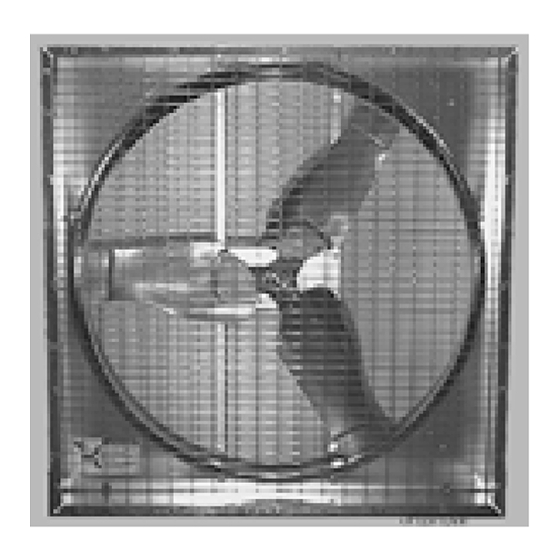
36" (50485) & 48" (50454) Hyflo
Retrofit Kit
Installation & Operator's Instruction Manual
Safety
DANGER: Electrical Hazard
Disconnect electrical power before inspecting or servicing
equipment unless maintenance instructions specifically state
otherwise. Ground all electrical equipment for safety. All
electrical wiring must be done by a qualified electrician in
accordance with local and national electric codes. Ground all non-
current carrying metal parts to guard against electrical shock. With
the exception of motor overload protection, electrical disconnects
and over current protection are not supplied with the equipment.
DANGER: Rotating Fan Blade
Keep Hands away. Disconnect power before servicing. Fan may
start automatically. Do not operate the Fan without the screens in
place.
Disregard to the above mentioned Danger may cause serious
injury including death.
• Keep all Safety Signs and decals in good condition.
• Replace damaged or missing decals.
October 2012
MV1902C
Advertisement

Subscribe to Our Youtube Channel
Summary of Contents for Chore-Time Hyflo 50485
- Page 1 ® 36" (50485) & 48" (50454) Hyflo Retrofit Kit Installation & Operator’s Instruction Manual Safety DANGER: Electrical Hazard Disconnect electrical power before inspecting or servicing equipment unless maintenance instructions specifically state otherwise. Ground all electrical equipment for safety. All electrical wiring must be done by a qualified electrician in accordance with local and national electric codes.
- Page 2 Installing the new Door Assembly and Cone 36" (50485) & 48" (50454) Hyflo® Retrofit Kit Installing the new Door Assembly and Cone Cone Assembly and Installation Begin assembling the Cone by laying a Cone Panel (Item 1, Figure 3) on a couple of boards with the c- shaped drain tab (Item 2) towards the front as shown.
- Page 3 36" (50485) & 48" (50454) Hyflo® Retrofit Kit Installing the new Door Assembly and Cone Orient the Door Assembly such that the bottom is lined up with one of the C-Shaped Drain Tab in the Cone Assembly. The bottom of the Door Assembly can be identified by a drain hole in the Ring (See Figure 5).
- Page 4 Installing the new Door Assembly and Cone 36" (50485) & 48" (50454) Hyflo® Retrofit Kit Attaching the Door Stop Cable to Grill, and the Grill to the Cone Step 1: Line up the Grill Eyehooks with the holes in the Cone. Thread the free end of the Door Stop Cable (Nylon Cable) (Item 2) through the bottom Grill Eyehook(Item 1) until it is flush with the Cone and secure it with a 5/16-18 Carriage Bolt (Item 3) and Flange Nut (Item 4) as shown.
- Page 5 36" (50485) & 48" (50454) Hyflo® Retrofit Kit Installing the new Door Assembly and Cone Attaching the Cone Attaching Cone Brackets to Shroud Use 5/16 x 1/2" Carriage Bolts (Item 1, Figure 9) and 5/16 Flange Nuts (Item 2) to attach the four Cone Brackets (Item 3) to the Fan Shroud as shown below.
- Page 6 Installing the new Door Assembly and Cone 36" (50485) & 48" (50454) Hyflo® Retrofit Kit Leveling Doors and tightening down Cone Hardware Use a Level and rotate the Cone and Door Assembly until the Center Screen Wire (Item 1, Figure 11) is Vertical (See Figure).
-
Page 7: Door Spring Installation
36" (50485) & 48" (50454) Hyflo® Retrofit Kit Installing the new Door Assembly and Cone Door Spring Installation At the middle of the Door Center Brace (Item 1, Figure 12), attach the Spring Mounting Bracket (Item 2, Included in the Parts Package) as shown in Step 1 below. Hook the rounded ends of the Door Springs (Item 3) onto the Spring Mounting Bracket. -
Page 8: Kit Parts
Kit Parts 36" (50485) & 48" (50454) Hyflo® Retrofit Kit Kit Parts 3 12 3 11 3 15 3 17 Door Cut Away for View of Magnet and Rivet 3 13 3 18 50454 (48" Kit) 50485 (36" Kit) Item Description Part Number Metal Cone Fan Grill... - Page 9 36" (50485) & 48" (50454) Hyflo® Retrofit Kit Kit Parts This Page left Blank Intentionally..MV1902C...
-
Page 10: Revisions To This Manual
Page No. Description of Change Various Added 48" Kit Contact your nearby Chore-Time distributor or representative for additional parts and information. CTB Inc. P.O. Box 2000 • Milford, Indiana 46542-2000 • U.S.A. Phone (574) 658-4101 • Fax (877) 730-8825 E-Mail: ctb@ctbinc.com • Internet: http//www.ctbinc.com Printed in the U.S.A.


Need help?
Do you have a question about the Hyflo 50485 and is the answer not in the manual?
Questions and answers