Sign In
Upload
Manuals
Brands
GESTRA Manuals
Controller
URB 50
GESTRA URB 50 Manuals
Manuals and User Guides for GESTRA URB 50. We have
2
GESTRA URB 50 manuals available for free PDF download: Installation Instructions Manual, Original Installation Instructions
GESTRA URB 50 Installation Instructions Manual (44 pages)
Conductivity Controller, Operating & Display Unit
Brand:
GESTRA
| Category:
Controller
| Size: 1 MB
Table of Contents
Table of Contents
2
Important Notes
5
Usage for the Intended Purpose
5
Glossary
5
Function
7
Safety Note
8
Directives and Standards
9
EU Pressure Equipment Directive 2014/68/EU
9
VdtüV Bulletin "Water Monitoring 100
9
LV (Low Voltage) Directive and EMC (Electromagnetic Compatibility)
9
ATEX (Atmosphère Explosible)
9
Ul/Cul (CSA) Approval
9
Note on the Declaration of Conformity / Declaration by the Manufacturer
9
Technical Data
10
Lrr 1-52, Lrr 1-53
10
Only LRR 1-52
11
Only LRR 1-53
11
Lrr 1-52, Lrr 1-53
11
Urb 50
12
Scope of Supply
12
Conductivity Controller LRR
12
Lrr
12
In Control Cabinet: Installing the Conductivity Controller
13
Dimensions LRR 1-52, LRR 1-53
13
Key
13
Installation in Control Cabinet
13
Name Plate / Marking
14
In Control Cabinet: Installing the Operating & Display Unit
15
Dimensions URB 50
15
Key
15
Installation in Control Cabinet
15
Name Plate / Marking
15
In Control Cabinet: Wiring the Conductivity Controller
16
Wiring Diagram for Conductivity Controller LRR 1-52
16
Wiring Diagram for Conductivity Controller LRR 1-53
17
Key
17
Transmitter LRGT 1
17
Valve
17
Actual Value Output 4-20 Ma
17
Contents - Continued
18
In Control Cabinet: Wiring the Operating & Display Unit
18
Back of Equipment, Position of Connector
18
Connection of Supply Voltage
18
Pin Assignment for Data Line LRR 1-52, LRR 1-53 - URB 50
18
Key
18
In Control Cabinet
19
Wiring the Conductivity Controller / the Operating & Display Unit
19
Connection of Supply Voltage
19
Connecting Output Contacts
19
Resistance Thermometer TRG 5
19
Connection of Conductivity Electrode LRG16-9
19
Connection of Conductivity Transmitter LRGT 1
20
Connection of Data Line for the Conductivity Controller / Operating & Display Unit
20
Connecting the Potentiometer (for Indication of Valve Positions), Connections in ../ out / 4-20 Ma
20
In the Plant
21
Wiring the Conductivity Electrode / Transmitter
21
Connecting Conductivity Electrode LRG 12-2, LRG 16-4, LRG 17-1 and LRG 19-1, Resistance Thermome- Ter TRG 5
21
Connection of Conductivity Electrode LRG16-9
21
Connection of Conductivity Transmitter LRGT 1
21
Conductivity Controller: Factory Settings
22
Conductivity Controller LRR 1-52, LRR 1-53
22
Conductivity Controller: Changing Factory Settings
23
Changing the Function and Unit
23
Tools
24
Operating & Display Unit URB 50
25
User Interface
25
Key
25
Switch on Supply Voltage
25
Explanation of Icons
26
Operating & Display Unit URB 50
26
Contents - Continued
29
Commissioning Procedure
29
Adjusting the MIN/MAX Switchpoints and Setpoint
29
Numberpad
29
Key
29
Conductivity Controller LRR 1-52: Setting the Measuring Range, Correction Factor and Temperature Compensation
30
Key
30
Conductivity Controller LRR 1-53: Setting Measuring Range
31
Setting the Control Parameters
32
Additional Information on Control Parameter Settings
32
Continuous Blowdown Valve: Setting the Purging Pulse and Duration
33
Continuous Blowdown Valve: Calibrating the Potentiometer for Indication of Valve Position
33
Key
33
Indication of Valve Position (Indicated in Percent and as Bar Graph)
33
Automatic Intermittent Blowdown
34
Operation
35
Manual Actuation of Continuous Blowdown Valve
35
Stand-By Operation
35
Key
35
Trending
36
Key
36
Testing MIN/MAX Alarm, Entering Date and Time
37
Setting up a Password and Logging in
38
Key
38
Setting up a Password and Logging in
39
Log out
39
Alarm List
40
Key
40
Error, Alarm and Warning Messages
41
Indication, Diagnosis and Remedy
41
Further Notes
42
Action against High Frequency Interference
42
Decommissioning / Replacing the Conductivity Controller LRR 1-5
42
Decommissioning / Replacing the Operating & Display Unit URB 50
42
Disposal
42
Advertisement
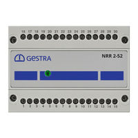
GESTRA URB 50 Original Installation Instructions (40 pages)
Level Controller, Operating & Display Unit
Brand:
GESTRA
| Category:
Controller
| Size: 1 MB
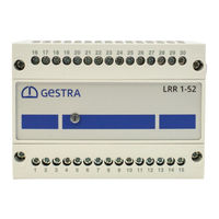
Table of Contents
Table of Contents
2
Important Notes
5
Usage for the Intended Purpose
5
Function
5
Safety Note
6
Directives and Standards
6
VdtüV Bulletin "Wasserstand 100" (= Water Level 100)
6
LV (Low Voltage) Directive and EMC (Electromagnetic Compatibility)
6
ATEX (Atmosphère Explosible)
6
Ul/Cul (CSA) Approval
6
Note on the Declaration of Conformity / Declaration by the Manufacturer
6
Technical Data
7
Nrr 2-52, Nrr 2-53
7
Scope of Supply
9
In Control Cabinet: Mounting Level Controller
10
Dimensions NRR 2-52, NRR 2-53
10
Key
10
Installation in Control Cabinet
10
Name Plate / Marking
11
In Control Cabinet: Installing the Operating & Display Unit
12
Dimensions URB 50
12
Key
12
Installation in Control Cabinet
12
Name Plate / Marking
12
In Control Cabinet: Wiring Level Controller
13
Wiring Diagram for Level Controller NRR 2-52
13
Key
13
Wiring Diagram for Level Controller NRR 2-53
14
Key
14
In Control Cabinet: Wiring the Operating & Display Unit
15
Back of Equipment, Position of Connector
15
Connection of Supply Voltage
15
Pin Assignment for Data Line NRR 2-52, NRR 2-53 - URB 50
15
Key
15
In Control Cabinet: Wiring the Level Controller / the Operating & Display Unit
16
Connection of Supply Voltage
16
Connecting Output Contacts
16
Connecting Level Electrode, Level Transmitter
16
Connection of Data Line for the Level Controller / Operating & Display Unit
16
Connecting the Potentiometer (for Indication of Valve Positions), Connections in ../ out / 4-20 Ma
16
In the Plant
17
Wiring Level Electrode / Level Transmitter
17
Connecting Level Electrode, Level Transmitter
17
Level Controller: Factory Settings
17
Level Controller NRR 2-52, NRR 2-53
17
Level Controller: Changing Factory Settings
18
Changing Function and Input for Level Electrode/Transmitter
18
Tools
19
Before Putting the Level Control System into Operation
20
Establishing Measuring Range
20
Operating & Display Unit URB 50
21
User Interface
21
Key
21
Switch on Supply Voltage
21
Explanation of Icons
22
Commissioning Procedure
24
Adjusting the MIN/MAX Switchpoints and Setpoint
24
Numberpad
24
Key
24
Establishing Measuring Range for Level Electrode NRG 2
25
Setting the Control Parameters
26
Additional Information on Control Parameter Settings
26
Key
26
Setting the Control Parameters for 3-Element Control (Optional)
27
Key
27
Contents - Continued
28
Only NRR 2-52: Calibrating the Potentiometer for Indication of Valve Position
28
Operation
28
Manual Actuation of Control Valve
28
Trending
29
Key
29
Testing MIN/MAX Alarm, Entering Date and Time
30
Setting up a Password and Logging in
31
Key
31
Log out
33
Alarm & Malfunction List
34
Key
34
Error, Alarm and Warning Messages
35
Indication, Diagnosis and Remedy
35
Further Notes
36
Action against High Frequency Interference
36
Decommissioning / Replacing the Level Controller NRR 2-5
36
Decommissioning / Replacing the Operating & Display Unit URB 50
36
Disposal
36
Advertisement
Related Products
GESTRA URB 55
GESTRA URB 1
GESTRA URS 2
GESTRA URN 2
GESTRA URB 60
GESTRA URS 60
GESTRA URS 61
GESTRA UNA 46A MAX
GESTRA UNA 45
GESTRA UNA46AMAX
GESTRA Categories
Switch
Control Unit
Controller
Measuring Instruments
Industrial Equipment
More GESTRA Manuals
Login
Sign In
OR
Sign in with Facebook
Sign in with Google
Upload manual
Upload from disk
Upload from URL