Samlexpower Evolution Series Owner's Manual
Remote control for evolution series inverter/ charger
Hide thumbs
Also See for Evolution Series:
- Owner's manual (132 pages) ,
- Quick start manual (12 pages) ,
- Quick start manual (12 pages)
Table of Contents

Related Manuals for Samlexpower Evolution Series


Summary of Contents for Samlexpower Evolution Series
- Page 1 Remote Control for Owner's Please read this manual BEFORE Manual Evolution Series operating. Inverter/ Charger Model: EVO-RC-PLUS NOTE: REMOTE CONTROL MODEL NO. EVO-RC-PLUS IS OPTIONAL AND IS REQUIRED TO BE ORDERED SEPARATELY.
-
Page 2: Table Of Contents
EVO-RC OWNER'S MANUAL | Index SECTION 1 Introduction and Layout ............3 SECTION 2 Installation ................6 SECTION 3 Operation ................8 SECTION 4 Parameter Setup ..............27 SECTION 5 SD Card ................. 77 SECTION 6 Monitoring of Operation Using LED and Buzzer ....83 SECTION 7 Fault Messages and Troubleshooting Guide ....... -
Page 3: Introduction And Layout
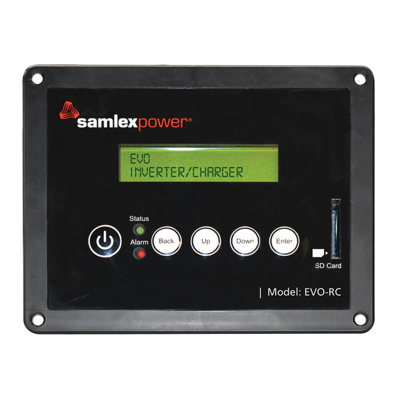
SECTION 1 | Introduction and Layout 1.0 INTRODUCTION The EVO-RC-PLUS Remote Control allows you to monitor and customize the operating pa- rameters of Samlex EVO Inverter/Chargers Models EVO-1212F / 1212F-HW, 1224F / 1224F- HW, 2212, 2224, 3012 and 4024. Layout is shown in Fig 1 below. It has its own internal Real Time Clock and Super Capacitor Type of Battery for clock operation. - Page 4 SECTION 1 | Introduction and Layout Top view of Plug - Locking Tab facing down Straight Front view of Plug - Connection Locking Tab RJ-45 RJ-45 facing up Pin # Signal Pin # Signal ON/OFF ON/OFF Pin Out of Pin Out of 8P 8C, RJ-45 Modular Plug Plug - End 1 Plug - End 2...
- Page 5 SECTION 1 | Introduction and Layout +12V D– NC Not connected D– +12V 6P4C Modular Plug 6P4C Modular Plug (Locking Tab (Locking Tab “A” “B-6P4C” Facing Down) Facing Down) 1 2 3 4 5 6 1 2 3 4 5 6 Black Green Yellow...
-
Page 6: Installation
SECTION 2 | Installation 2.0 INSTALLATION GUIDELINES EVO-RC-PLUS is provided with 10M/33ft, RJ-45 data cable (straight wired). Check the proposed routing distance of the wire and use longer wire, if necessary. • Flush mounting of the Remote requires appropriate cut-out in the wall/panel - See Fig 2.1. Full scale installation Template for panel cut-out and pilot holes for mounting screws is also provided along with the unit. - Page 7 SECTION 2 | Installation 1. Cut an opening in the wall using the supplied Installation Template (based on Fig 2.1). 2. Drill four pilot holes (use 2mm / 5/64" diameter drill bit) for 4 screw (Self Taping, Flat Head No. 6 x 5/8" long) that will attach the remote to the wall (refer to Fig. 2.1 for hole loca- tions and dimensions).
-
Page 8: Operation
SECTION 3 | Operation 3.0 GENERAL INFORMATION EVO-RC-PLUS Remote Control provides the user with the ability to monitor the operation and also to modify EVO Inverter/Charger’s operating parameters. The default settings in EVO Inverter/Charger are adequate for some installations but may have to be modified for others. This Section provides details on the remote functions, status and menu maps and displays, fault messages and parameter settings. - Page 9 SECTION 3 | Operation 3.2 POWER ON / POWER OFF INFO a) Minimum battery voltage required for initiating manual switching ON of the unit is as follows: • 12V units ----- Higher than 9V • 24V units ---- Higher than 18V b) Please note that this unit is designed to POWER ON AUTOMATICALLY if (i) AC voltage of 70V ±...
- Page 10 SECTION 3 | Operation 3.2.2 Power OFF - AC INPUT IS NOT PRESENT The sequence given below is applicable when no AC input is present and the unit is powered OFF. Press On/Off Key and hold for 5 seconds to turn OFF the EVO Inverter/Charger.
- Page 11 SECTION 3 | Operation • On the front panel of EVO No LED display. LED marked “ON” and Red LED marked “FAULT” will both be OFF. No buzzer LED marked "ON" (12, Fig 2.1 in the Owner's Manual for Evolution Series Inverter/Charger) will blink once every 5 sec.
- Page 12 SECTION 3 | Operation Table 3.1 Operating Modes and Associated LCD Display Screens Operating Mode Screen Menu Map Models Operating EVO-1212F / Models Mode 1212F HW / 1224F / EVO-2212 / 3012 / Display Description 1224F-HW 2224 / 4024 Standby Standby Mode: No output, No AC Fig 3.1(a), Fig 3.1 (b),...
- Page 13 SECTION 3 | Operation 3.6.2 Menu Map for Standby Mode Screens Menu Maps for the Operating Mode Screens for the Standby Mode are shown as follows: Ÿ Section 3.6.2.1: Fig 3.1(a) for Models EVO-1212F / 1212F-HW / 1224F / 1224F-HW (Model No.
- Page 14 SECTION 3 | Operation 3.6.2.2 Menu Map for Standby Mode Screens for EVO-2212 / 3012 / 2224 / 4024 E V O - 3 0 1 2 S t a n d b y E V O - 3 0 1 2 S t a n d b y o u t p u t : 0 .
- Page 15 SECTION 3 | Operation 3.6.3 Menu Map for Inverting Mode Screens Menu Maps for the Operating Mode Screens for the "Inverting" Mode are shown as follows: Ÿ Section 3.6.3.1: Fig 3.2(a) for Models EVO-1212F / 1212F-HW / 1224F / 1224F-HW (Model No.
- Page 16 SECTION 3 | Operation 3.6.3.2 Menu Map for Inverting Mode Screens for Models EVO-2212 / 3012 / 2224 / 4024 E V O - 3 0 1 2 I n v e r t i n g E V O - 3 0 1 2 I n v e r t i n g O u t p u t : 1 2 0 .
- Page 17 SECTION 3 | Operation 3.6.4 Menu Map for Charging Mode Screens Menu Map for the Operating Mode Screens for the "Charging" Mode are shown as follows: Ÿ Section 3.6.4.1: Fig 3.3(a) for Models EVO-1212F / 1212F-HW / 1224F / 1224F-HW (Model No.
- Page 18 SECTION 3 | Operation 3.6.4.2 Menu Map for Charging Mode Screens for Models EVO-2212 / 3012 / 2224 / 4024 E V O - 3 0 1 2 C h a r g i n g E V O - 3 0 1 2 F C h a r g i n g 0 - B u l k S t a g e...
- Page 19 SECTION 3 | Operation 3.6.4.3 Details of Charging Profiles in Charging Mode Screens Refer to the 2 Line of the following Charging Mode Screens: Ÿ Fig 3.3(a) under Section 3.6.4.1 for Models EVO-1212F / 1212F-HW / 1224F / 1224F-HW Ÿ Fig 3.3(b) under Section 3.6.4.2 for Models EVO-2212 / 3012 / 2224 / 4024 Details of information related to this line on the screen are shown in Table 3.2.
- Page 20 SECTION 3 | Operation 3.6.5 Menu Maps for Power Save Mode Screens Menu Maps for the Operating Mode Screens for the Power Save Mode are shown as follows: Ÿ Section 3.6.5.1: Fig 3.4(a) for Models EVO-1212F / 1212F-HW / 1224F / 1224F-HW (Model No.
- Page 21 SECTION 3 | Operation 3.6.5.2 Menu Maps for Power Save Mode Screens for EVO-2212 / 3012 / 2224 / 4024 E V O - 3 0 1 2 P o w e r S a v e E V O - 3 0 1 2 P o w e r S a v e o u t p u t :...
- Page 22 SECTION 3 | Operation 3.6.6 Menu Maps for On-Line Mode Screens Menu Maps for the On-Line Mode Screens will be similar to the following Menu Map Screens for the default Off-Line Mode except for some changes explained below: Menu Map Screens for Models Menu Map Screens for Models Mode EVO-1212F / 1212F-HW / 1224F / 1224F-HW...
- Page 23 SECTION 3 | Operation 3.6.7 Menu Maps for "Chgr Only" (Charger Only) Mode Screens Menu Maps for the Operating Mode Screens for the "Chgr Only" Mode are shown as follows: Ÿ Fig 3.6(a) for Models EVO-1212F / 1212F-HW / 1224F / 1224F-HW (Model No. shown in the screens is EVO-1212F).
- Page 24 SECTION 3 | Operation 3.6.7.2 Menu Map for "Chgr Only" (Charger Only) Mode Screens for EVO-2212 / 3012 / 2224 / 4024 E V O - 3 0 1 2 C h g r O n l y E V O - 3 0 1 2 C h g r O n l y I n v e r t e r...
- Page 25 SECTION 3 | Operation 3.6.8 Menu Map for "Charger Off by BMS" Mode Screens This mode is applicable when option BATTERY TYPE 1 = Lithium is selected (see Screen No. 22 at Table 4.3 for Group 1 Parameter Setup-CHARGE CURVE). This mode is activated when the Battery Management System (BMS) of the Lithium Battery sends a command (contact closure) to pins 4 and 5 of the RJ-45 Temperature Sensor Jack on the EVO Inverter/Charger (Temperature Sen-...
- Page 26 SECTION 3 | Operation 3.6.9 Menu Map for "Inverter stop by BMS" Mode Screens for Models EVO-1212F / 1212F-HW / 1224F / 1224F-HW Menu Map for Operating Mode Screens for "Inverter stop by BMS" Mode is shown in Fig 3.8 below.
-
Page 27: Parameter Setup
SECTION 4 | Parameter Setup 4.0 "SELECT GROUP" AND "SELECT PARAMETER" MENU MAPS 4.1.1 General Information Up to 58 operating parameters can be programmed to suit the desired operating conditions. The programmable parameters have been arranged under 7 Parameter Groups as per details at Table 4.1 below. - Page 28 SECTION 4 | Parameter Setup 4.1.2 "Select Group" Menu Map Menu Map for "Select Group" is shown at Fig 4.1 below: S e l e c t G r o u p C H A R G E C U R V E Screen No.
- Page 29 SECTION 4 | Parameter Setup 4.1.3 "Select Parameter" Menu Map When any of the 7 Parameter Groups from the "Select Group" Menu Map (Fig 4.1) is selected, access is available to the "Select Parameter" Menu Map pertaining to that Group. Location of "Select Parameter"...
- Page 30 SECTION 4 | Parameter Setup 4.1.3.1 "Select Parameter" Menu Map for Parameter Group 1: CHARGE CURVE S e l e c t P a r a m e t e r S e l e c t P a r a m e t e r S e l e c t P a r a m e t e r C H A R G E...
- Page 31 SECTION 4 | Parameter Setup 4.1.3.2 "Select Parameter" Menu Maps for (i) Parameter Group 2: INPUT SETTING, (ii) Parameter Group 3: INPUT LOW LIMIT and (iii) Parameter Group 4: INPUT HIGH LIMIT. Parameter Group 2 Parameter Group 3 Parameter Group 4 "INPUT SETTING"...
- Page 32 SECTION 4 | Parameter Setup 4.1.3.3 "Select Parameter" Menu Map for Parameter Group 5: OTHER FUNCTION S e l e c t P a r a m e t e r S e l e c t P a r a m e t e r O T H E R F U N C T I O N O T H E R...
- Page 33 SECTION 4 | Parameter Setup 4.1.3.4 "Select Parameter" Menu Maps for (i) Parameter Group 6: TIME SET- TING and (ii) Parameter Group 7: STOP SD CARD Group 6 Group 7 "TIME SETTING" "STOP SD CARD" S e l e c t P a r a m e t e r S e l e c t P a r a m e t e r...
- Page 34 SECTION 4 | Parameter Setup ð Press Enter Key Press Down Key ð Press Back Key Press Up Key "Select Parameter" Screen (Figs 4.2 to 4.5) Any Operating Mode "Select Group" (eg. BULK CURRENT: Screen from Fig 3.1 to 3.5 Menu Map (Fig 4.1) Screen No.
- Page 35 SECTION 4 | Parameter Setup 2 digits. Hence, for EVO-1212F / 1212F-HW, the numerical value of BULK CURRENT will be displayed /entered as 2 digits. For example, 1A will be displayed / entered as “1A”; 20A will be displayed / entered as "20A" and so on. The overall numerical value of the parameter is changed digit by digit starting from the 1st digit on the left.
- Page 36 SECTION 4 | Parameter Setup 4.3.1 Example of Password Activation and Changing Bulk Current Setting for EVO-1212F / 1212F-HW from Default Value of 20A to 50A Starting from any of the 5 Operating Mode Screens (shown S e l e c t G r o u p C H A R G E C U R V E...
- Page 37 SECTION 4 | Parameter Setup Screen No.1 of the "Select Parameter - CHARGE CURVE" S e t u p P a r a m e t e r C H A R G E C U R V E for BULK CURRENT setting appears as shown on the left.. B U L K C U R R E N T The Default Value of 20A will be displayed as “20”...
- Page 38 SECTION 4 | Parameter Setup 4.3.2 Disabling Password Protection In the default / factory preset condition, Password Protection is enabled. Password Protection may be disabled, if required. Procedure is given below: 1. Press ENTER Key momentarily from any Operating Mode Screen (see details at Table 3.1) S e l e c t G r o u p •...
- Page 39 SECTION 4 | Parameter Setup P a s w o r d c o r r e c t • Flashes twice when Password is correct. (8052) P a s w o r d e r r o r ! ! •...
- Page 40 SECTION 4 | Parameter Setup 4.4 GROUP 1 PARAMETER SETUP: CHARGE CURVE 4.4.1 Programming Ranges and Default / Factory Preset Values or Parameters Under - Group 1 - CHARGE CURVE Table 4.3 below gives details of programming ranges and default values of parameters under Group 1 - "CHARGE CURVE".
- Page 41 SECTION 4 | Parameter Setup Table 4.3 Group 1 Parameter Set Up: CHARGE CURVE (Continued) EVO-1212F EVO-1224F Screen EVO-1212F-HW EVO-2212 EVO-3012 EVO-1224F-HW EVO-2224 EVO-4024 Parameter “EQUALIZE-4STAGES” 0=No (3-stage) ; 1=Yes (4-stage) (4 Stage Charging (0=No ) On/Off) 0 = Normal (Default)..Grid / Generator priority Also called Off-Line Mode 1 = On-Line....Inverter priority "MODE”...
- Page 42 SECTION 4 | Parameter Setup Current is in the range of 10% to 20% of the Ah capacity of the battery bank at C/20 Discharge Rate. Check with the battery manufacturer regarding recommended Bulk Charging Current for your battery bank. This value of “Bulk Charging Current” should be programmed as “BULK CURRENT”.
- Page 43 SECTION 4 | Parameter Setup 4.4.2.2 ABSORP VOLTAGE (Table 4.3 , Screen No. 2) This sets the charging voltage in the Constant Voltage Absorption Stage. Enter Key Down Key x 1 time Enter Key S e l e c t G r o u p S e l e c t P a r a m e t e r...
- Page 44 SECTION 4 | Parameter Setup 4.4.2.5 COMPENSATE (Table 4.3, Screen No. 5) This parameter sets the temperature compensation for the battery. The operational range of the EVO Inverter/Charger is -20°C to 60°C. This compensation voltage will affect the Absorption Voltage/Equalize Voltage/Floating Voltage/ Batt Over Volt/Restart Voltage/Low Volt Alarm/Batt Low Voltage when the Temperature Sensor is installed on the battery (see Fig 2.5 in the Owner's Manual for Evolution Series Inverter/Charger).
- Page 45 SECTION 4 | Parameter Setup 4.4.2.7 RESET VOLTAGE (Table 4.3, Screen No. 7) • The inverter will restart when the battery voltage rises to this set value or above after "Bat- tery low voltage!" shutdown occurs. • If automatic starting / stopping of Generator is used with RELAY FUNCTION set at "3= Generator 1"...
- Page 46 SECTION 4 | Parameter Setup 4.4.2.9 BATT LOW VOLTAGE (Table 4.3, Screen No. 9) This parameter sets the battery low voltage threshold at which the Inverter Section / the com- plete EVO Inverter/Charger will be shut down to protect the battery from deep discharge: •...
- Page 47 SECTION 4 | Parameter Setup 4.4.2.10 LV DETECT TIME (Table 4.3, Screen No. 10) To prevent "Battery low voltage!" fault and shut down of the inverter due to momentary dips in battery voltage as a result of high power, short duration AC loading (e.g. motor starting, inrush current etc.), a timer is used to qualify "BATT LOW VOLTAGE"(Section 4.4.2.9) condition only if the battery voltage drops to or below the set “BATT LOW VOLTAGE”...
- Page 48 SECTION 4 | Parameter Setup 4.4.2.12 EQUALIZE – 4 STAGES (Table 4.3, Screen No. 12) Parameter "CHARGING PROFILE" (Section 4.4.2.21) allows option to select from 3 versions of 3-Stage and 2 versions of 2-Stage charging Profiles. Default option is "0=3-Stage Adaptive". The charging profile can be changed AT ANY TIME to 4-Stage Equalize profile through programmable parameter "EQUALIZE-4STAGES"...
- Page 49 SECTION 4 | Parameter Setup 4.4.2.13.1 Charger Only Mode (Table 4.3, Screen No. 13) Under the MODE Menu (Section 4.4.2.13), 3 options can be programmed: 0=Normal (Offline Mode) or 1=Online or 2=Charger Only. When “Charger Only” Mode is selected (2=Charger Only), the EVO will charge the batteries and pass through the AC input power to the loads as long as AC input is available.
- Page 50 SECTION 4 | Parameter Setup Details of the two options are given below: 0= Option 1 (Default): • The Transfer Relay will be switched ON (energized) if the battery voltage drops to “LOW VOLT ALARM” (Section 4.4.2.8) or lower for sustained period = “GS DETECT TIME”...
- Page 51 SECTION 4 | Parameter Setup 4.4.2.15 RESET TO BULK (Table 4.3, Screen No. 15) Please refer to Sections 5.7.4 and 5.9.1 of the Owner's Manual for Evolution Series Inverter/ Chargers EVO-1212F / 1212F-HW / 1224F / 1224F-HW regarding automatic resetting of charg- ing profiles.
- Page 52 SECTION 4 | Parameter Setup 4.4.2.17 GEN ON TIME (Table 4.3, Screen No. 17) This parameter is a Programmable Timer (0-240 min; Default: 60 min) that is used for program- ming Automatic Starting and Stopping of Generator [Section 4.8.2.5.2(c)]. The Timer sets the duration the Generator will remain ON from the time the Status Relay has been switched ON (energized).
- Page 53 SECTION 4 | Parameter Setup 4.4.2.19 ABSORP TIME (Table 4.3 , Screen No. 19) Parameter “ABSORP TIME” is used to set the time the charger will remain in Absorption Stage when the following "CHARGING PROFILE" options are selected: • 1=3 Stage Type 1 (Refer to Section 4.4.2.21) •...
- Page 54 SECTION 4 | Parameter Setup Details of the 5 programmable charging profiles are given in Table 5.2. NOTE: 4-Stage Equalize Charging Profile is also available and can be activated anytime dur- ing charging taking place under one of the 5 Charging Profile options given above. Procedure to activate Equalize Charging Profile is described under programmable Parameter "EQUALIZE-4STAGES"...
- Page 55 SECTION 4 | Parameter Setup Options for Param- Battery Type and eter "CHARGING Battery Loading PROFILE" Charging Stages Condition 1. Bulk Stage: Charge at constant current equal to 2 = 3 Stage Type 2 • Lead Acid: Flooded programmable parameter “BULK CURRENT” and Sealed –...
- Page 56 SECTION 4 | Parameter Setup 4.4.2.22 BATTERY TYPE (Table 4.3, Screen No. 22) Parameter “BATTERY TYPE” is used to change the function of the Temperature Sensor Jack on the EVO Inverter / Chargers (6, Fig 2.1 in the EVO Manual) to accept potential free relay contact closure control signal from the Battery Management System (BMS) of Lithium Battery for stopping charging / inverting.
- Page 57 SECTION 4 | Parameter Setup • EVO in Inverting Mode: Inverting will stop. EVO will go to Standby Mode. The right half of the 1st Line of the Standby Mode Screens shown in the Menu Map for Standby Mode Screens [Fig 3.1(a) and 3.1(b)] will show “Inv stop by BMS” in 2 con- secutive displays - first “Inv stop”...
- Page 58 SECTION 4 | Parameter Setup NOTES for Table 4.5: 1. Values within brackets "( )" show the Default Setting. 2. DEFAULT FREQ parameter is fixed al 60Hz for EVO-1212F / 1212F-HW and EVO-1224F / 1224F-HW (Option 0=60Hz). If option 1 is entered, the screen line will show "! 1=xxHz"...
- Page 59 SECTION 4 | Parameter Setup 4.5.2.2.1 GRID MAX CURRENT (Table 4.5, Screen No. 2) Down Key x 1 time Enter Key Down Key x 1 time S e l e c t G r o u p S e l e c t P a r a m e t e r S e l e c t P a r a m e t e r...
- Page 60 SECTION 4 | Parameter Setup 4.5.2.5 HIGH RESET (Table 4.5, Screen No. 5) This is the reset frequency at which the unit will revert to "Charging Mode" after it has switched over to "Inverter Mode" due to input frequency rising above "HIGH CUT OFF". Down Key Enter Key Down Key x 4 times...
- Page 61 SECTION 4 | Parameter Setup 4.6 GROUP 3 PARAMETER SET UP: INPUT LOW LIMIT 4.6.1 Programming Ranges and Default / Factory Preset Values of Parameters under Group 3 - INPUT LOW LIMIT Table 4.6 below gives details of programming ranges and default values of parameters under Group 3 - INPUT LOW LIMIT.
- Page 62 SECTION 4 | Parameter Setup 4.6.2.2 CUT OFF VOLT 1 (Table 4.6, Screen No. 2) If during "Charging Mode", the AC input voltage falls below "CUT-OFF VOLT 1" for period > "DETECT TIME 1", the EVO Inverter/Charger will transfer to Inverting Mode from "Charging Mode". Down Key x 2 times Enter Key Down Key x 1 time...
- Page 63 SECTION 4 | Parameter Setup 4.6.2.5 DETECT TIME 2 (Table 4.6, Screen No. 5) This is the time limit in cycles up to which low AC input voltage "CUT-OFF 2" is allowed. Down Key x 2 times Enter Key Down Key x 4 times S e l e c t G r o u p S e l e c t...
- Page 64 SECTION 4 | Parameter Setup 4.7 GROUP 4 PARAMETER SET UP: INPUT HIGH LIMIT 4.7.1 Programming Ranges and Default / Factory Preset Values of Parameters under Group 4 - INPUT HIGH LIMIT TABLE 4.7 below gives details of programming ranges and default values of parameters under Group 4 - INPUT HIGH LIMIT.
- Page 65 SECTION 4 | Parameter Setup 4.7.2.2 CUT OFF VOLT 1 (Table 4.7, Screen No. 2) If during "Charging Mode", the AC input voltage rises above "CUT-OFF VOLT 1" for period > "DETECT TIME 1", the EVO Inverter/Charger will transfer to "Inverting Mode". Down Key x 3 times Enter Key Down Key x 1 time...
- Page 66 SECTION 4 | Parameter Setup 4.7.2.5 DETECT TIME 2 (Table 4.7, Screen No. 5) This is the time limit in cycles up to which high AC input voltage "CUT-OFF VOLT 2" is allowed. Down Key x 3 times Enter Key Down Key x 4 times S e l e c t G r o u p...
- Page 67 SECTION 4 | Parameter Setup 4.8 GROUP 5 PARAMETER SET UP: OTHER FUNCTIONS Please refer to Parameters under Group 5 at Fig 4.2. Details of Parameter set up are given below: 4.8.1 Programming Ranges and Default / Factory Preset Values of Parameters under Group 5 - OTHER FUNCTION Table 4.8 below gives details of programming ranges and default values of parameters under Group 5 - OTHER FUNCTION.
- Page 68 SECTION 4 | Parameter Setup 4.8.2 Description of Parameters under Group 5 - OTHER FUNCTION 4.8.2.1 POWER SAVING (Table 4.8, Screen No. 1) Enable or disable Power Saving Mode when in "Inverting Mode". Down Key x 4 times Enter Key Enter Key S e l e c t G r o u p...
- Page 69 SECTION 4 | Parameter Setup 4.8.2.4 REMOTE SWITCH (Table 4.8, Screen No. 4) This selection is used when ON/OFF control of EVO Inverter/Charger is desired through external 12 VDC signal fed to Remote ON/OFF terminals on the Front Panel of EVO Inverter/Charger [(i)15, Fig 2.1 in EVO Inverter/Charger Owner's Manual for EVO-2212/3012/2224/4024 and...
- Page 70 SECTION 4 | Parameter Setup Down Key x 4 times Enter Key Down Key x 3 times S e l e c t G r o u p S e l e c t P a r a m e t e r S e l e c t P a r a m e t e r C H A R G E...
- Page 71 SECTION 4 | Parameter Setup 4.8.2.5.1 (b) Automatic Starting and Stopping of Generator (Options 2, 3 and 4) NOTE: Applicable for Models EVO-2212 / 3012 / 2224 / 4024 ONLY. INFO The following programmable parameters have been referred to in the description be- low.
- Page 72 SECTION 4 | Parameter Setup Relay Options 2, 3 and 4 related to automatic starting and stopping of generator are explained below: 4.8.2.5.2(a) Option 2 = Generator 0 (This is the Default Option): This Option will start the Generator at “LOW VOLT ALARM” and stop the Generator when the batteries are fully charged till completion of 3-Stage Charging Cycle.
- Page 73 SECTION 4 | Parameter Setup • If the battery voltage drops to “LOW VOLT ALARM” [(i) for 12V: 9.5V – 12.5V / Default 11.0V (ii) for 24V: 19.0V – 25.0V / Default 22.0V] or lower for continuous period = “GS DETECT TIME” (0-600 sec; Default 10 sec), the Status Relay will be switched ON (energized).
- Page 74 SECTION 4 | Parameter Setup 4.8.2.7 BUZZER (Table 4.8, Screen No. 7) Set the buzzer ON/OFF. Down Key x 4 times Enter Key Down Key x 6 times S e l e c t G r o u p S e l e c t P a r a m e t e r S e l e c t P a r a m e t e r...
- Page 75 SECTION 4 | Parameter Setup timing. Time interval between recordings (called “DATALOG TIME”) is programmable. “Events” and “Errors” are recorded as soon as they are sensed. In the default setting, Data Logging is enabled. Data Logging can be disabled by setting programming option “0=Disable”. Programming options and procedure are shown below: Programming Options (i) 0=Disable, (ii) 1=1 sec (Default), (iii) 2=10 sec, (iv) 3=30 sec, (iv) 4=60 sec, (vi) 5=5 min, (vii) 6=10 min...
- Page 76 SECTION 4 | Parameter Setup 4.8.2.13 PASSWORD DISABLE (Table 4.8, Screen No. 13) In default condition, Password (8052) is required to change the value of programmable pa- rameter. Use of Password prevents accidental change of parameter setting. Password may be disabled, if required. Down Key x 4 times Enter Key Down Key x 12 times...
-
Page 77: Sd Card
SECTION 4 | Parameter Setup Down Key x 6 times Enter Key Down Key x 1 time S e l e c t G r o u p S e l e c t G r o u p S e l e c t P a r a m e t e r C H A R G E C U R V E... - Page 78 SECTION 5 | SD Card 5.2 DATA LOGGING As mentioned at Section 5.1 above, external SD Card may be used to log operating information. • When the SD Card is inserted in the SD Card Slot, data logging is activated automatically (it will be disabled only if programmable setting has been changed to “0=Disable) A Real Time Clock inside the EVO-RC Remote Control records timing.
- Page 79 SECTION 5 | SD Card Data log function has been initiated and new file is being F i l e c r e a t i n g . . . created. Do not remove the SD card when file creating is displayed.
- Page 80 SECTION 5 | SD Card Table 5.2 shows an example of one of the File’s contents opened with a general purpose Text Reader. The 1 Row shows the Model No. of the EVO .The 2 Row shows Data fields sepa- rated by semicolon i.e.
- Page 81 SECTION 5 | SD Card Fig 5.2 Screen Shot of Step 1 of "Text Import Wizard" in Excel • Text Import Wizard – Step 2 will appear (see Fig 5.3). Choose "Semicolon" and click 'Finish' button. Fig 5.3 Screen Shot of Step 2 of "Text Import Wizard" in Excel SAMLEX AMERICA INC.
- Page 82 SECTION 5 | SD Card • Data as in Fig 5.4 will be displayed on your Worksheet, with the Log Data stored in Columns and Rows. Fig 5.4 Screen Shot and Data Log Work Sheet 5.4 SAVING / UPLOADING PROGRAMMED PARAMETERS 5.4.1 Saving Programmed Parameters All the programmed parameters can be saved on an SD Card (FAT 16 / FAT 32 Format, up to 16 GB capacity).
-
Page 83: Monitoring Of Operation Using Led And Buzzer
SECTION 5 | SD Card 5.4.2 Uploading Saved Parameters If there is a “xxxx_yyy.cfg” file in the SD card with stored programmed parameters, then on inserting the card, the Remote Control will ask to upload the Config File. Press Enter Button to confirm or Back Key to cancel. -
Page 84: Fault Messages And Troubleshooting Guide
SECTION 7 | Fault Messages and Troubleshooting Guide TABLE 7.1 FAULT MESSAGES AND TROUBLESHOOTING GUIDE NOTES: 1. Please see Table 6.1 for LED indications in EVO-RC and buzzer indications in EVO Inverter/Charger 2. Buzzer is available only in EVO Inverter/Charger. There is no buzzer in Remote Control EVO-RC Fault Message Symptoms and Trouble Shooting Inverter/Charger is in FAULT MODE because the battery voltage has dropped to... - Page 85 SECTION 7 | Fault Messages and Troubleshooting Guide Inverter/Charger is in FAULT MODE because the battery voltage has risen to the set upper threshold of “BATT OVER VOLTAGE” (a) AC input is not available and EVO Inverter/Charger is operating in Inverting Mode: •...
- Page 86 SECTION 7 | Fault Messages and Troubleshooting Guide Fault Message Symptoms and Trouble Shooting Inverter/Charger is in FAULT MODE because there is a short circuit on the output side in Inverter Mode. Short circuit protection is activated when: (i) EVO-1212F/1212F- HW/1224F/1224F-HW: Output voltage is <...
-
Page 87: Specifications
SECTION 7 | Fault Messages and Troubleshooting Guide Fault Message Symptoms and Trouble Shooting • Data logging will not start. • Check that the format is FAT16/FAT32. SD card unusable! • Check that the capacity is less than 16 GB. •... -
Page 88: Warranty
SECTION 9 | Warranty 2 YEAR LIMITED WARRANTY EVO-RC-PLUS manufactured by Samlex America, Inc. (the “Warrantor“) is warranted to be free from defects in workmanship and materials under normal use and service. The warranty period is 2 years for the United States and Canada, and is in effect from the date of purchase by the user (the “Purchaser“). - Page 89 Notes SAMLEX AMERICA INC. | 89...
- Page 90 Notes 90 | SAMLEX AMERICA INC.
- Page 91 Notes SAMLEX AMERICA INC. | 91...
- Page 92 Contact Information Toll Free Numbers Ph: 1 800 561 5885 Fax: 1 888 814 5210 Local Numbers Ph: 604 525 3836 Fax: 604 525 5221 Website www.samlexamerica.com USA Shipping Warehouses Kent, WA Plymouth, MI Canadian Shipping Warehouse Delta, BC Email purchase orders to orders@samlexamerica.com 11025-EVO-RC-PLUS-0218...
Need help?
Do you have a question about the Evolution Series and is the answer not in the manual?
Questions and answers