Table of Contents
Advertisement
Quick Links
Remote Control for
Evolution
TM
Inverter/ Charger
Model: EVO-RC-PLUS
NOTE: REMOTE CONTROL MODEL NO. EVO-RC-PLUS IS OPTIONAL AND IS REQUIRED TO BE ORDERED SEPARATELY.
Owner's
Manual
Series
Please read this
manual BEFORE
operating.
Firmware
Version: 0.30
Advertisement
Table of Contents

Related Manuals for Samlexpower EVO-RC-PLUS


Summary of Contents for Samlexpower EVO-RC-PLUS
- Page 1 Remote Control for Owner's Please read this manual BEFORE Manual Evolution Series operating. Inverter/ Charger Model: EVO-RC-PLUS Firmware Version: 0.30 NOTE: REMOTE CONTROL MODEL NO. EVO-RC-PLUS IS OPTIONAL AND IS REQUIRED TO BE ORDERED SEPARATELY.
-
Page 2: Table Of Contents
EVO-RC-PLUS OWNER'S MANUAL | Index SECTION 1 Introduction and Layout ............3 SECTION 2 Installation ................6 SECTION 3 Operation ................8 SECTION 4 Parameter Setup ..............28 SECTION 5 SD Card ................ 96 SECTION 6 Monitoring of Operation Using LED and Buzzer ....103 SECTION 7 Fault Messages and Troubleshooting Guide ..... -
Page 3: Introduction And Layout
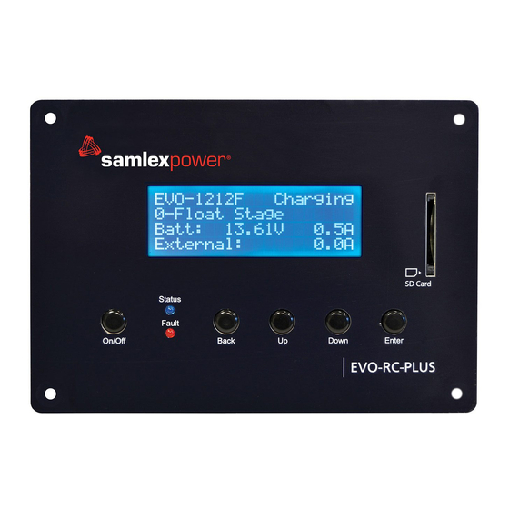
Introduction and Layout 1.0 INTRODUCTION The EVO-RC-PLUS Remote Control allows you to monitor and customize the operating parameters of Samlex EVO™ Inverter/Chargers Models EVO-1212F / 1212F-HW, 1224F / 1224F-HW, 2212, 2224, 3012 and 4024. Layout is shown in Fig 1 below. - Page 4 1 2 3 4 5 6 7 8 123456 1 2 3 4 5 6 7 8 RJ-12 (6P6C) Jack RJ-45 (8P8C) Jack Fig 1.3 Pinout and internal interconnections of RJ-45 and RJ-12 (6P6C) Jacks on EVO-RC-PLUS 4 | SAMLEX AMERICA INC.
- Page 5 [Fig 1.4] and rewired as shown Connect to “A” Connect to RJ-45 Jack 6P6C Jack on marked “Remote Control” EVO-RC-PLUS 1 2 3 4 5 6 1 2 3 4 5 6 7 8 on EVO-2212/3012/2224/4024 Black Black or EVO-1212F/1212F-HW/...
-
Page 6: Installation
SECTION 2 | Installation 2.0 INSTALLATION GUIDELINES EVO-RC-PLUS is provided with 10M/33ft, RJ-45 data cable (straight wired). Check the proposed routing distance of the wire and use longer wire, if necessary. • Flush mounting of the Remote requires appropriate cut-out in the wall/panel - See Fig 2.1. - Page 7 3. Route one end of the cable through wall opening to the EVO™ Inverter/Charger, and then plug it into the RJ-45 Remote Control Jack port on the EVO™ Inverter/Charger 4. Take the other end of the remote cable and plug it into the RJ-45 / RJ-12 Jack at the back of the EVO-RC-PLUS (Fig. 2.3).
-
Page 8: Operation
Operation 3.0 GENERAL INFORMATION EVO-RC-PLUS Remote Control provides the user with the ability to monitor the operation and also to modify EVO™ Inverter/Charger’s operating parameters. The default settings in EVO™ Inverter/Charger are adequate for some installations but may have to be modified for others. This Section provides details on the remote functions, status and menu maps and displays, fault messages and parameter settings. - Page 9 CANNOT BE POWERED OFF using the ON / OFF Button on the front panel of the unit or on the Remote Control EVO-RC-PLUS. Switch OFF the AC input first if the unit is required to be powered off. However, if the unit is in “Fault Mode”, it will be possible to power OFF the unit with the help of the ON/OFF Push Button on the EVO ™...
- Page 10 Standby Mode as explained at Section 3.4.1.1 below. Once Standby Mode has been entered using EVO-RC-PLUS Remote Control, it can ALSO be switched off using the On/Off Push Button on the front panel of the EVO Inverter-Charger Unit (See Section 3.4.1.2) If EVO-RC-PLUS Remote Control has NOT been connected to the EVO Inverter-Charger Unit, Standby •...
- Page 11 Manual) and Buzzer will be off 3.4.1.2 Exiting Standby Mode: Using EVO-RC-PLUS: To exit Standby Mode using EVO-RC-PLUS, press the On/Off Key (2, Fig 1.1) momentarily (0.1 sec). From Front Panel of EVO Inverter Charger Unit: To exit Standby Mode from the EVO unit, momentarily (0.1 sec) press the On/Off Push Button on the front panel of the EVO (11, Fig 2.1 of the EVO Inverter-Charger...
- Page 12 SECTION 3 | Operation 3.5. FAULT MESSAGES & CLEARING FAULTS If any fault occurs, the LCD screen will display the Fault Message and the Red LED “Fault” (4, Fig 1.1) will be lighted. Refer to Table 7.1 at Section 7 for details of various fault messages and procedure to clear the fault. CAUTION! The cause of the fault should be removed before the unit is restarted.
- Page 13 SECTION 3 | Operation Table 3.1 Operating Modes and Associated Menu Maps/ LCD Display Screens Operating Mode Screen Menu Map Models Operating EVO-1212F / Models Mode 1212F HW / 1224F / EVO-2212 / 3012 / Display Description 1224F-HW 2224 / 4024 Standby Standby Mode: No output, No AC bypass, No Charging Fig 3.1(a),...
- Page 14 SECTION 3 | Operation 3.6.2.1 Menu Map for Standby Mode Screens for EVO-1212F / 1212F-HW / 1224F / 1224F-HW E V O - 1 2 1 2 F S t a n d b y E V O - 1 2 1 2 F S t a n d b y o u t p u t : 0 .
- Page 15 SECTION 3 | Operation 3.6.2.2 Menu Map for Standby Mode Screens for EVO-2212 / 3012 / 2224 / 4024 E V O - 3 0 1 2 S t a n d b y E V O - 3 0 1 2 S t a n d b y o u t p u t : 0 .
- Page 16 SECTION 3 | Operation 3.6.3 Menu Map for Inverting Mode Screens Menu Maps for the Operating Mode Screens for the "Inverting" Mode are shown as follows: • Section 3.6.3.1: Fig 3.2(a) for Models EVO-1212F / 1212F-HW / 1224F / 1224F-HW (Model No.
- Page 17 SECTION 3 | Operation 3.6.3.2 Menu Map for Inverting Mode Screens for Models EVO-2212 / 3012 / 2224 / 4024 E V O - 3 0 1 2 I n v e r t i n g E V O - 3 0 1 2 I n v e r t i n g O u t p u t : 1 2 0 .
- Page 18 SECTION 3 | Operation 3.6.4 Menu Map for Charging Mode Screens Menu Maps for the Operating Mode Screens for the "Charging" Mode are shown as follows: • Section 3.6.4.1: Fig 3.3(a) for Models EVO-1212F / 1212F-HW / 1224F / 1224F-HW (Model No.
- Page 19 SECTION 3 | Operation 3.6.4.2 Menu Map for Charging Mode Screens for EVO-2212 / 3012 / 2224 / 4024 E V O - 3 0 1 2 C h a r g i n g E V O - 3 0 1 2 C h a r g i n g 0 - B u l k S t a g e...
- Page 20 SECTION 3 | Operation 3.6.4.3 Details of Charging Profiles in Charging Mode Screens Refer to the 2nd Line of the following Charging Mode Screens: • Fig 3.3(a) under Section 3.6.4.1 for Models EVO-1212F / 1212F-HW / 1224F / 1224F-HW • Fig 3.3(b) under Section 3.6.4.2 for Models EVO-2212 / 3012 / 2224 / 4024 Details of information related to this line on the screen are shown in Table 3.2.
- Page 21 SECTION 3 | Operation 3.6.5 Menu Map for Power Save Mode Screens Menu Maps for the Operating Mode Screens for the "Power Save" Mode are shown as follows: • Section 3.6.5.1: Fig 3.4(a) for Models EVO-1212F / 1212F-HW / 1224F / 1224F-HW (Model No.
- Page 22 SECTION 3 | Operation 3.6.5.2 Menu Map for Power Save Mode Screens for EVO-2212 / 3012 / 2224 / 4024 E V O - 3 0 1 2 P o w e r S a v e E V O - 3 0 1 2 P o w e r S a v e o u t p u t...
- Page 23 SECTION 3 | Operation 3.6.6 Menu Maps for On-Line Mode Screens Menu Maps for the On-Line Mode Screens will be similar to the following Menu Map Screens for the default Off-Line Mode except for some changes explained below: Menu Map Screens for Models Menu Map Screens for Models Mode EVO-1212F / 1212F-HW / 1224F / 1224F-HW...
- Page 24 SECTION 3 | Operation 3.6.7 Menu Map for "Chgr Only" (Charger Only) Mode Screens Menu Maps for the Operating Mode Screens for the "Chgr Only" Mode are shown as follows: • Fig 3.6(a) for Models EVO-1212F / 1212F-HW / 1224F / 1224F-HW (Model No.
- Page 25 SECTION 3 | Operation 3.6.7.2 Menu Map for "Chgr Only" (Charger Only) Mode Screens for EVO-2212 / 3012 / 2224 / 4024 E V O - 3 0 1 2 C h g r O n l y E V O - 3 0 1 2 C h g r O n l y I n v e r t e r...
- Page 26 SECTION 3 | Operation 3.6.8 Menu Map for Charging Mode Screens When Charging is Switched Off by the Lithium Ion Battery Management System (BMS) For background information, please refer to Sections 4.4.2.22.1 & 4.4.2.22.2 This Menu Map is applicable when parameter "BATTERY TYPE" is set for option "1=Lithium" (See Section 4.4.2.22). Screens shown below will be seen when the Battery Management System (BMS) of the Lithium Battery sends a command (potential free contact closure signal) to pins 4 and 5 of the RJ-45 Temperature Sensor Jack on the EVO™...
- Page 27 SECTION 3 | Operation 3.6.9 Menu Map for Inverting Mode Screens When Inverting is Stopped by the Lithium Ion Battery Management System (BMS) For background information, please refer to Sections 4.4.2.22.1 & 4.4.2.22.2 This Menu Map is applicable when parameter "BATTERY TYPE" is set for option "1 = Lithium" (See Section 4.4.2.22.1) Screens shown below will be seen when the Battery Management System (BMS) of Lithium Battery sends a command (potential free contact closure signal) to pins 4 and 5 of the RJ-45 Temperature Sensor Jack on the EVO™...
- Page 28 SECTION 4 | Parameter Setup 4.0 "SELECT GROUP" AND "SELECT PARAMETER" MENU MAPS 4.1.1 General Information A number of operating parameters can be programmed to suit the desired operating conditions. The programming parameters have been arranged under 7 groups (displayed as "SELECT GROUP" as per details at Table 4.1 below. "Select Group"...
- Page 29 SECTION 4 | Parameter Setup 4.1.2 "Select Group" Menu Map Menu Map for "Select Group" is shown at Fig 4.1 below: S e l e c t G r o u p C H A R G E C U R V E Screen No.
- Page 30 SECTION 4 | Parameter Setup 4.1.3 "Select Parameter" Menu Map When any of the 7 Parameter Groups from the "Select Group" Menu Map (Fig 4.1) is selected, access is available to the "Select Parameter" Menu Map pertaining to that Group. Location of "Select Parameter" Menu Maps are given in Table 4.2.
- Page 31 SECTION 4 | Parameter Setup 4.1.3.1 "Select Parameter" Menu Map for Parameter Group 1: CHARGE CURVE S e l e c t P a r a m e t e r S e l e c t P a r a m e t e r S e l e c t P a r a m e t e r Screen...
- Page 32 G E N – No. 9 3. These screens are displayed only when EVO-RC-PLUS is used for models EVO- C o a r s e 2212 / 3012 / 2224 / 4024. These screens are NOT displayed in EVO-1212F /...
- Page 33 SECTION 4 | Parameter Setup 4.1.3.3 "Select Parameter" Menu Map for Parameter Group 5: OTHER FUNCTION S e l e c t P a r a m e t e r S e l e c t P a r a m e t e r O T H E R F U N C T I O N O T H E R...
- Page 34 SECTION 4 | Parameter Setup 4.1.3.4 "Select Parameter" Menu Maps for (i) Parameter Group 6: TIME SETTING and (ii) Parameter Group 7: STOP SD CARD Group 6 Group 7 "TIME SETTING" "STOP SD CARD" S e l e c t P a r a m e t e r S e l e c t P a r a m e t e r...
- Page 35 SECTION 4 | Parameter Setup ð Press Enter Key Press Down Key ð Press Back Key Press Up Key "Select Parameter" Screen (Figs 4.2 to 4.5) Any Operating Mode "Select Group" (eg. BULK CURRENT: Screen from Fig 3.1 to 3.5 Menu Map (Fig 4.1) Screen No.
- Page 36 SECTION 4 | Parameter Setup 4.2.2 Changing / Entering Parameter Values Each parameter has a programmable range of values specific to the model number of the EVO™. Please refer to Tables 4.3 and 4.6 to 4.9 and Sections 4.9 and 4.10 for details. During parameter programming, the displayed numerical value of the parameter consists of multiple digits that are necessary to display the highest numerical value within the programmable range.
- Page 37 SECTION 4 | Parameter Setup 4.3.1 Example of Password Activation and Changing Bulk Current Setting for EVO-1212F / 1212F- HW from Default Value of 20A to 50A Starting from any of the 5 Operating Mode Screens (shown at Figs S e l e c t G r o u p C H A R G E C U R V E...
- Page 38 SECTION 4 | Parameter Setup Screen No.1 of the "Select Parameter - CHARGE CURVE" for BULK S e t u p P a r a m e t e r C H A R G E C U R V E CURRENT setting appears as shown on the left..
- Page 39 SECTION 4 | Parameter Setup 4.3.2 Disabling Password Protection In the default / factory preset condition, Password Protection is enabled. Password Protection may be disabled, if required. Procedure is given below: 1. Press ENTER Key momentarily from any Operating Mode Screen (see details at Table 3.1) S e l e c t G r o u p •...
- Page 40 SECTION 4 | Parameter Setup P a s w o r d c o r r e c t • Flashes twice when Password is correct. (8052) P a s w o r d e r r o r ! ! •...
- Page 41 SECTION 4 | Parameter Setup Table 4.3 Group 1 Parameter Set Up: CHARGE CURVE (Refer to Menu Map at Fig 4.2, Section 4.1.3.1) Parameter EVO-1212F EVO-1224F Setup Parameter EVO-1212F-HW EVO-2212 EVO-3012 EVO-1224F-HW EVO-2224 EVO-4024 Screen No. (Column 1) (Column 2) (Column 3) (Column 4) (Column 5)
- Page 42 SECTION 4 | Parameter Setup 4.4.2 Description of Parameters under Group 1 - CHARGE CURVE 4.4.2.1 BULK CURRENT (Table 4.3, Screen No. 1) Parameter "BULK CURRENT" sets the maximum charging current during the Bulk Charging Stage. The default value is 20A for EVO-1212F / 1212F-HW, 20A for EVO-1224F / 1224F-HW and 40A for EVO-2212 / EVO-3012 / EVO-2224 / EVO-4024.
- Page 43 SECTION 4 | Parameter Setup 4.4.2.1.1 Programming Steps for Parameter "BULK CURRENT" Any Operating Mode Screen from Fig 3.1 to 3.5 Enter Key Enter Key Enter Key Enter Key E V O - 1 2 1 2 F I n v e r t i n g S e l e c t G r o u p S e l e c t...
- Page 44 SECTION 4 | Parameter Setup 4.4.2.4 FLOAT VOLTAGE (Table 4.3, Screen No. 4) This sets the charging voltage in the Constant Voltage Float Stage. 4.4.2.4.1 Programming Steps for Parameter "FLOAT VOLTAGE" Any Operating Mode Screen from Fig 3.1 to 3.5 Enter Key Enter Key Enter Key...
- Page 45 SECTION 4 | Parameter Setup 4.4.2.5.1 Programming Steps for Parameter "COMPENSATE" Any Operating Mode Screen from Fig 3.1 to 3.5 Enter Key Enter Key Enter Key Down Key x 4 times E V O - 1 2 1 2 F I n v e r t i n g S e l e c t G r o u p...
- Page 46 SECTION 4 | Parameter Setup 4.4.2.7 RESET VOLTAGE (Table 4.3, Screen No. 7) • The inverter will restart when the battery voltage rises to this set value or above after "Battery low voltage!" shutdown occurs (Section 7, Srl. No. 1 of Table 7.1) •...
- Page 47 SECTION 4 | Parameter Setup 4.4.2.9 BATT LOW VOLTAGE (Table 4.3, Screen No. 9) This parameter sets the battery low voltage threshold at which the Inverter Section / the complete EVO Inverter/ ™ Charger will be shut down to protect the battery from deep discharge: 4.4.2.9.1 BATTERY LOW VOLTAGE (Value of parameter LV CUT OFF TIME set from 1 to 7200 sec) •...
- Page 48 SECTION 4 | Parameter Setup 4.4.2.9.2.3 Automatic switching over to “Charging Mode” has 2 options selectable through programming parameter “INPUT RECOVERY” (Section 4.5.2.11) as follows: a) Option 0=Buffered (Default): Under this option, the unit will initially start in “Inverting Mode”, synchronize with the AC input and then transfer to “Charging Mode”.
- Page 49 SECTION 4 | Parameter Setup 4.4.2.11 LV CUT OFF TIME (Table 4.3, Screen No. 11) 4.4.2.11.1 Value of LV CUT OFF TIME: 1 to 7200 sec Even when the Inverter Section is shut down due to “Battery low voltage!” fault condition as described at Section 4.4.2.9, there will still be some power drawn from the battery to keep the other circuitry in the EVO™...
- Page 50 SECTION 4 | Parameter Setup TABLE 4.4 CHARGING PROFILE FOR 4-STAGE ADAPTIVE CHARGING FOR EQUALIZATION Options under Programming Charging Stages Battery Type Parameter “EQUALIZE–4 STAGES” 1. Stage 1 – Bulk Stage (See Section 5.8.2 of the EVO- − Lead Acid: Flooded only EQUALIZE –...
- Page 51 SECTION 4 | Parameter Setup 4.4.2.12.1 Programming Steps for Parameter "EQUALIZE-4STAGES" Any Operating Mode Screen from Fig 3.1 to 3.5 Enter Key Enter Key Enter Key Down Key x 11 times E V O - 1 2 1 2 F I n v e r t i n g S e l e c t G r o u p...
- Page 52 SECTION 4 | Parameter Setup E V O - 1 2 1 2 F S t a n d b y O u t p u t : 0 . 0 0 V < 0 . 1 0 A 6 0 . 0 0 H z •...
- Page 53 SECTION 4 | Parameter Setup • The Transfer Relay will be switched ON (energized) if the battery voltage drops to the voltage threshold of “LOW VOLT ALARM” (Section 4.4.2.8) or lower for sustained period = “GS DETECT TIME” (Section 4.4.2.16). The EVO™ will change over to “Charging Mode”...
- Page 54 SECTION 4 | Parameter Setup 4.4.2.15 RESET TO BULK (Table 4.3, Parameter Setup Screen No. 15) Refer to Table 4.3, Screen No. 15 Further, refer to the description of 6 types of charging profiles under parameter "CHARGING PROFILE" (Section 4.2.2.21). Parameter "RESET TO BULK"...
- Page 55 SECTION 4 | Parameter Setup 4.4.2.17 GEN ON TIME (Table 4.3, Parameter Setup Screen No. 17) This parameter is a Programmable Timer (0-240min; Default: 60 min) that is used for programming Automatic Starting and Stopping of Generator [Section 4.8.2.5.2(c)]. The Timer sets the duration the Generator will remain ON from the time the Status Relay has been switched ON (energized).
- Page 56 SECTION 4 | Parameter Setup 4.4.2.19 ABSORP TIME (Table 4.3, Parameter Setup Screen No. 19) Parameter “ABSORP TIME” is used to set the time the charger will remain in Absorption Stage when the following options for programming parameter “Charging Profile” (See Section 4.4.2.21) are selected: •...
- Page 57 SECTION 4 | Parameter Setup 4.4.2.21 CHARGING PROFILE (Table 4.3, Parameter Setup Screen No. 21) Parameter “CHARGING PROFILE” provides 6 options for Charging Profiles that are designed to cover various charging requirements for Lead Acid, Nickel-Zinc (Ni-Zn) and Lithium Ion Batteries. INFO 7th Charging Profile i.e.
- Page 58 SECTION 4 | Parameter Setup TABLE 4.5 CHARGING PROFILE OPTIONS FOR 3 AND 2-STAGE CHARGING Options under Programming Parameter Charging Stages Battery Type “CHARGING PROFILE” 0 = 3 Stage Adaptive 1. Stage 1 – Bulk Stage (For details, see Section 5.7.1.1 of the Owner's Manual for EVO- −...
- Page 59 SECTION 4 | Parameter Setup 2=3Stage Type2 1. Stage 1 – Bulk Stage (For details, see Section 5.7.1.1 of the Owner's Manual for EVO- − Lead Acid: Flooded 1212F/1212F-HW/1224F/1224F-HW): and Sealed – AGM/ • Charge at constant current = the programmed value of parameter “BULK Gel Cell CURRENT”...
- Page 60 SECTION 4 | Parameter Setup 4=2Stage Type2 1. Stage 1 – Bulk Stage (For details, see Section 5.7.1.1 of the Owner's Manual for EVO- − Lithium (For details, 1212F/1212F-HW/1224F/1224F-HW): see Section 5.11 of Owner's Manual for • Charge at constant current = the programmed value of parameter “BULK CURRENT”...
- Page 61 SECTION 4 | Parameter Setup 4.4.2.22 BATTERY TYPE (Table 4.3, Parameter Setup Screen No. 22) 4.4.2.22.1 General Information Parameter “BATTERY TYPE” is used to change the functionality of RJ-45 Jack marked “Battery Temp. Sensor” on the front panel of EVO [6, Fig 2.1 in EVO-1212F/1212F-HW/1224F/1224F-HW Owner’s Manual]. The following 2 programming options are available: a) Option 1 - “0=Lead Acid”...
- Page 62 SECTION 4 | Parameter Setup b) Wiring Connection: Output from the SSR Terminals on the Lithium Battery BMS should be wired to the RJ- 45 Jack marked “Battery Temp. Sensor” (6, Fig 2.1 in the EVO-1212F/1212F-HW/1224F/1224F-HW Owner's Manual) as follows: Connect terminal marked “+”...
- Page 63 SECTION 4 | Parameter Setup NOTE: Parameter “CHARGING PROFILE” will be required to be programmed to select the desired charging profile for the Lithium Ion Battery from the following options: • 1=3 Stage Type 1 • 2=3 Stage Type 2 •...
- Page 64 SECTION 4 | Parameter Setup • Parameter “LV CUT OFF TIME” [Section 4.4.2.11.2] is set to 0 sec to ensure that the unit does not shut down completely if AC input is not restored before expiry of time set through programming parameter “LV CUT OFF TIME”...
- Page 65 External Solar Charge Controller Charging current from the Internal AC Charger = Programmed value of Parameter “BULK CURRENT” (Section 4.4.2.1 of Remote-Control Manual for EVO-RC-PLUS) MINUS value of charging current from the External Solar Charge Controller i) Programming Parameter “EXT CHARGER” set at Option “0 = Not affect” (Section 4.4.2.24 of Remote...
- Page 66 SECTION 4 | Parameter Setup 4.5 GROUP 2 PARAMETER SET UP: INPUT SETTING 4.5.1 Programming Ranges & Default Values of Programming Parameters under Parameter Group 2 – INPUT SETTING Table 4.6 gives details of programming ranges & default values of parameters under Parameter Group No.2 - "INPUT SETTING" . Refer to Fig 4.3 under Section 4.1.3.2 for Menu Map for navigating through various parameters under this Group No.2.
- Page 67 SECTION 4 | Parameter Setup 4.5.2 Description of Parameters under Parameter Group No.2 – INPUT SETTING 4.5.2.1 DEFAULT FREQ: (Table 4.6, Parameter Setup Screen No.1) Default frequency sets the Inverter frequency, which is also the standard frequency for AC input. 4.5.2.1.1 Programming Steps for Parameter "DEFAULT FREQUENCY"...
- Page 68 SECTION 4 | Parameter Setup 4.5.2.2.1 Programming Steps for Parameter "GRID MAX CURRENT" Any Operating Mode Screen from Fig 3.1 to 3.5 Enter Key Down Key x 1 time Down Key x 1 time Enter Key E V O - 1 2 1 2 F I n v e r t i n g S e l e c t G r o u p...
- Page 69 SECTION 4 | Parameter Setup 4.5.2.4 HIGH CUT OFF (Table 4.6: (i) Parameter Setup Screen No.3 for EVO-1212F/EVO-1212F-HW/EVO-1224F/EVO-1224F-HW (ii) Parameter Setup Screen No.4 for EVO-2212/EVO-3012/EVO-2224/EVO-4024) If the AC input frequency is over the value of “HIGH CUT OFF” when in "Charging Mode", the EVO™ Inverter/ Charger will transfer to Inverting Mode.
- Page 70 SECTION 4 | Parameter Setup 4.5.2.6.1 Programming Steps for Parameter "LOW CUT OFF" (i) Down Key x 4 times for EVO- 1212F/1212F-HW/1224F/1224F-HW Any Operating Mode Screen from (ii) Down Key x 5 times for EVO- Fig 3.1 to 3.5 Enter Key Down Key x 1 time 2212/3012/2224/4024 Enter Key...
- Page 71 SECTION 4 | Parameter Setup When EVO™ is operating in Inverting Mode (there is no AC input), its output frequency will be equal to the frequency that has been selected by the programming parameter “DEFAULT FREQ” (TABLE 4.6 and Section 4.5.2.1). When AC input is made available, it is first monitored for 2 sec.
- Page 72 SECTION 4 | Parameter Setup 4.5.2.8.1 Programming Steps for Parameter “SYNCHRONIZATION” Any Operating Mode Screen from Fig 3.1 to 3.5 Enter Key Down Key x 7 times Down Key x 1 time Enter Key E V O - 1 2 1 2 F I n v e r t i n g S e l e c t G r o u p...
- Page 73 SECTION 4 | Parameter Setup First, the frequency of the Inverter Section is tracked in steps of 0.1Hz per cycle and made equal to the frequency of the Grid / Inverter Generator input. ii. Then, the phase of the Inverter voltage relative to the Grid voltage is tracked by 1º per cycle. When the phase of the Inverter voltage is within ±...
- Page 74 SECTION 4 | Parameter Setup NOTE: For supplementary details on synchronized transfer of AC power, please refer to Section 4.5.4 to 4.5.7 of Owner’s Manual for EVO-2212/3012/2224/4024 Parameter “SYNC GEN” is used to program the desired sensitivity of frequency and phase synchronization of the Inverter Section with the AC input voltage fed at the AC Input Terminals marked “GEN”...
- Page 75 SECTION 4 | Parameter Setup ii. Then, the phase of the Inverter voltage relative to the phase of the Grid / Inverter Generator voltage is tracked by 1º per cycle. When the phase of the Inverter voltage is within ± 3.5º of the input voltage waveform, the Transfer Relay is activated to transfer the AC load from the Grid / Inverter Generator to the Inverter Section at zero crossing of the voltage waveform.
- Page 76 SECTION 4 | Parameter Setup Fault message “Input over current” will be displayed on the LCD screen, Blue LED marked “Status” • will be switched off and Red LED marked “Fault” will be switched on. The unit will be latched in OFF condition and will require manual reset by powering off the unit, waiting for 1 min and then, powering on again 4.5.2.11.1 Programming Steps for Parameter “INPUT OC PROTECT”...
-
Page 77: Parameter Setup
SECTION 4 | Parameter Setup 4.5.2.12.1 Programming Steps for Parameter “INPUT RECOVERY” (i) Down Key x 8 times for EVO- 1212F/1212F-HW/1224F/1224F-HW Any Operating Mode Screen from (ii) Down Key x 10 times for EVO- Fig 3.1 to 3.5 Enter Key Down Key x 1 time Enter Key 2212/3012/2224/4024... - Page 78 SECTION 4 | Parameter Setup 4.6.2.1.1 Programming Steps for Parameter "RESET VOLTAGE" Any Operating Mode Screen from Fig 3.1 to 3.5 Enter Key Enter Key Down Key x 2 times Enter Key E V O - 1 2 1 2 F I n v e r t i n g S e l e c t G r o u p...
- Page 79 SECTION 4 | Parameter Setup 4.6.2.4 CUT OFF VOLT 2 (Table 4.7, Parameter Setup Screen No.4) If during "Charging Mode", the AC input voltage falls below "CUT-OFF VOLT 2" for period > "DETECT TIME 2", the EVO™ Inverter/Charger will transfer to "Inverting Mode". 4.6.2.4.1 Programming Steps for Parameter "CUT OFF VOLT 2"...
- Page 80 SECTION 4 | Parameter Setup 4.6.2.7 DETECT TIME 3 (Table 4.7, Parameter Setup Screen No.7) This is the time limit in cycles up to which low AC input voltage "CUT-OFF VOLT 3"is allowed. 4.6.2.7.1 Programming Steps for Parameter "DETECT TIME 3" Any Operating Mode Screen from Fig 3.1 to 3.5 Enter Key...
- Page 81 SECTION 4 | Parameter Setup 4.7.2 Description of Parameters Under Group 4 – INPUT HIGH LIMIT 4.7.2.1 RESET VOLTAGE (Table 4.8, Parameter Setup Screen No.1) This is the reset voltage at which the unit will revert to "Charging Mode" after it has switched over to "Inverting Mode" due to input AC voltage rising to "CUT-OFF VOLT 1/CUT-OFF VOLT 2/CUT-OFF VOLT 3.
- Page 82 SECTION 4 | Parameter Setup 4.7.2.4 CUT OFF VOLT 2 (Table 4.8, Parameter Setup Screen No.4) If during "Charging Mode", the AC input voltage rises above "CUT-OFF VOLT 2" for period > "DETECT TIME 2", the EVO™ Inverter/Charger will transfer to "Inverting Mode". 4.7.2.4.1 Programming Steps for Parameter "CUT OFF VOLT 2"...
- Page 83 SECTION 4 | Parameter Setup 4.7.2.7 DETECT TIME 3 (Table 4.8, Parameter Setup Screen No.7) This is the time limit in cycles up to which high AC input voltage "CUT-OFF VOLT 3"is allowed. 4.7.2.7.1 Programming Steps for Parameter "DETECT TIME 2" Any Operating Mode Screen from Fig 3.1 to 3.5 Enter Key...
- Page 84 SECTION 4 | Parameter Setup TABLE 4.9 Group 5 Parameter Set Up: OTHER FUNCTION (Refer to Menu Map at Fig 4.4, Section 4.1.3.3 Parameter Setup Setting range Parameter Setup Screen Nos. for Screen Nos. for EVO-1212F/ EVO-2212/ 3012/ 1212F-HW/ 1224F/ 2224/ 4024 Parameter EVO-1212F...
- Page 85 SECTION 4 | Parameter Setup 4.8.2 Description of Parameters Under Group 5 – OTHER FUNCTION 4.8.2.1 POWER SAVING (Table 4.9, Parameter Setup Screen No.1) INFO For more information on use and application of Power Save Functions, please refer to Sections 4.6.3 & 4.6.4 in the "Evolution Series Inverter/ Charger Owner's Manual for Models EVO-1212F/1212F-HW/1224F/1224F-HW."...
- Page 86 SECTION 4 | Parameter Setup 4.8.2.3 WAKE UP POINT (Table 4.9, Parameter Setup Screen No.3) INFO For more information on use and application of Power Save Functions, please refer to Sections 4.6.3 & 4.6.4 in the "Evolution Series Inverter/ Charger Owner's Manual for Models EVO-1212F/1212F-HW/1224F/1224F-HW." If the unit is in "Power Save Mode"...
- Page 87 SECTION 4 | Parameter Setup CAUTION! 1. On/Off Logic shown in Fig 4.8 also controls the operation of the On/Off Button on the front panel of EVO™ Inverter/Charger (11, Fig 2.1 in EVO™ Inverter/Charger Owner's Manual). The Default Setting is "0 = Button". 2.
- Page 88 SECTION 4 | Parameter Setup A Single Pole Double Throw (SPDT) Status Relay with 3 contacts (Contact Rating: 3A ; 125 VAC / 30 VDC) has been provided in the Evolution™ Series (EVO™) Inverter/Chargers EVO-2212 / 3012 / 2224 / 4024 that can be used for (i) signaling of operational status [Options 0 and 1 - See Section 4.8.2.5.1] and (ii) providing contact closure / opening for automatic starting and stopping of generator through appropriate optional Generator Auto Start / Stop Control Module (Options 2, 3 and 4 - See Sections 4.8.2.5.2.1 to 4.8.2.5.2.3).
- Page 89 SECTION 4 | Parameter Setup INFO It is recommended that “GSCM-Mini” Series of Generator Start / Stop Control Module, appropriate for the generator may be considered and ordered directly from Atkinson Electronics www.atkinsonelectronics.com. Based on the Generator Start Logic contained in of one of the selected Options 2, 3 or 4 explained below (See Sections 4.8.2.5.2.1 to 4.8.2.5.2.3), the Status Relay will be switched ON (energized), its “Common”...
- Page 90 SECTION 4 | Parameter Setup For Parameter “CHARGING PROFILE” (Section 4.4.2.21) set for 2 Stage Charging Profile as per “Option “3 = 2 Stage Type 1” The Status Relay will be de-energized to stop the Generator when the battery bank is charged •...
- Page 91 4.8.2.6 COMM ID (Table 4.9, (i) Parameter Setup Screen No. 5 under Column 1 (ii) Parameter Setup Screen No. 6 under Column 2) Communication ID- This sets the ID number for the COMM Port and EVO-RC/ EVO-RC-PLUS Remote Control. SAMLEX AMERICA INC. | 91...
- Page 92 SECTION 4 | Parameter Setup 4.8.2.6.1 Programming Steps for Parameter "COMM ID" (i) Down Key x 4 times for EVO- 1212F/1212F-HW/1224F/1224F-HW Any Operating Mode Screen from (ii) Down Key x 5 times for EVO- Fig 3.1 to 3.5 Enter Key Down Key x 4 times Enter Key 2212/3012/2224/4024...
- Page 93 / 1224F-HW and 28 Data Fields in Model Nos. EVO-2212 / 3012 / 2224 / 4024 that can be logged in external SD Card (Refer to Section 5.2.2 and 5.2.3 for details of the Data Fields). A Real Time Clock inside the EVO-RC-PLUS Remote Control records timing.
- Page 94 SECTION 4 | Parameter Setup 4.8.2.11.1 Programming Steps for Parameter "PARAMETER SAVE" (i) Down Key x 9 times for EVO- 1212F/1212F-HW/1224F/1224F-HW Any Operating Mode Screen from (ii) Down Key x 10 times for EVO- Fig 3.1 to 3.5 Enter Key Down Key x 4 times Enter Key 2212/3012/2224/4024...
- Page 95 SECTION 4 | Parameter Setup 4.9 GROUP 6 PARAMETER SETUP: TIME SETTING Please refer to Parameter "TIME SETTING" under Screen No. 6 for Group 6 at Fig 4.1. Set up details are given below. The Date and Time Format is Year/Month/Day Hour:Minute (24 hour clock): NOTE: Password is not required for setting this parameter.
-
Page 96: Sd Card
SECTION 5 | SD Card 5.1 SD CARD GENERAL INFORMATION SD Card slot has been provided for using an SD card for (i) data logging and (ii) saving programmed parameters. SD card supports FAT16/FAT32 format up to 16GB in size. When the SD card is inserted, the LCD screen will display the following. - Page 97 SECTION 5 | SD Card 5.2.2 DATA LOGGING Fields 5.2.2.1 DATA LOGGING Fields for Models EVO-1212F / 1212F-HW / 1224F / 1224F-HW The following 25 Data Fields consisting of various electrical parameters, events and error codes are recorded for Models EVO-1212F/1212F-HW/1224F/1224F-HW: Grid Grid...
- Page 98 SECTION 5 | SD Card 5.2.3 Operating Screens when SD Card is Inserted for Data Logging Data logging will be carried out automatically as soon as the SD Card is inserted in the SD Card Slot of EVO-RC. [Provided parameter “DATALOG TIME” (Section 4.8.2.10) has NOT been set to “0 = Disable”)]. Operating screens are shown below: F i l e c r e a t i n g .
- Page 99 SECTION 5 | SD Card TABLE 5.1 Example of Data Log Folder in SD Card's Root Directory Table 5.2 shows an example of one of the File’s contents opened with a general purpose Text Reader. The 1st Row shows the Model No. of the EVO™.The 2nd Row shows Data fields separated by semicolon i.e. ";" (see details of the Data fields at Section 5.2.2 and 5.2.3).
- Page 100 SECTION 5 | SD Card Fig 5.1 Screen Showing .txt Files • Click "Open" Button (Bottom right corner of Fig 5.1). • Text Import Wizard – Step 1 will be shown (Fig 5.2). Choose "Delimited"File Type". 100 | SAMLEX AMERICA INC.
- Page 101 SECTION 5 | SD Card Fig 5.2 Screen Shot of Step 1 of "Text Import Wizard" in Excel Text Import Wizard – Step 2 will appear (See Fig 5.3). Choose "Semicolon" and click 'Finish' button. • Fig 5.3 Screen Shot of Step 2 of "Text Import Wizard" in Excel •...
- Page 102 SECTION 5 | SD Card 5.4 SAVING / UPLOADING PROGRAMMED PARAMETERS 5.4.1 Saving Programmed Parameters All the programmed parameters can be saved on an SD Card (FAT 16 / FAT 32 Format, up to 16 GB capacity). The parameters will be saved in File named “xxxx_yyy.cfg”, where the first group of 4 digits xxxx is the Model No. e.g. 2212 or 2224 or 3012 or 4024 and the second group of 3 digits YYY is the Revision No.
-
Page 103: Monitoring Of Operation Using Led And Buzzer
Beep once in 1 sec interval Power saving Blink once in 3 sec interval Standby Blink once in 5 sec interval Fault NOTE: Buzzer is available only in EVO™ Inverter/Charger. There is no buzzer in Remote Control EVO-RC-PLUS. SAMLEX AMERICA INC. | 103... -
Page 104: Fault Messages And Troubleshooting Guide
TABLE 7.1 FAULT MESSAGES AND TROUBLESHOOTING GUIDE NOTES: 1. Please see Table 6.1 for LED indications in EVO-RC-PLUS and buzzer indications in EVO™ Inverter/Charger 2. Buzzer is available only in EVO™ Inverter/Charger. There is no buzzer in Remote Control EVO-RC-PLUS Srl. - Page 105 SECTION 7 | Fault Messages and Troubleshooting Guide Srl. Fault Message Symptoms and Troubleshooting • EVO™ is in FAULT MODE because the battery voltage has dropped momentarily for 1 ms to (i) 9V or below for EVO-1212F/1212F-HW/2212/ 3012 or, (ii) 18V or below for EVO-1224F/1224F- HW/2224/4024.
- Page 106 SECTION 7 | Fault Messages and Troubleshooting Guide Srl. Fault Message Symptoms and Troubleshooting EVO™ Inverter/Charger is in FAULT MODE because the battery voltage has risen to the set upper threshold of “BATT OVER VOLTAGE” (Section 4.4.2.6) (a) AC input is not available and EVO™ Inverter/Charger is operating in Inverting Mode: •...
- Page 107 SECTION 7 | Fault Messages and Troubleshooting Guide Srl. Fault Message Symptoms and Troubleshooting EVO™ Inverter/Charger is in FAULT MODE because of overload conditions in Inverting Mode: • There will be no AC output because the Inverter Section will be switched OFF. The Blue LED marked “Status”...
- Page 108 SECTION 7 | Fault Messages and Troubleshooting Guide Srl. Fault Message Symptoms and Troubleshooting EVO™ Inverter/Charger is in FAULT MODE because the main Bidirectional Transformer in the EVO™ Inverter/Charger has overheated to 150°C • The Blue LED marked “Status” will be switched OFF and the Red LED marked “Fault” will be steady ON.
-
Page 109: Specifications
SECTION 8 | Specifications 8.1 SPECIFICATIONS ITEM DESCRIPTION / SPECIFICATIONS Compatible Series Inverter/Charger Inverter/Chargers Display LCD Display 4 Rows, 20 Character each, Alpha-Numeric LCD Display LED Indicators Blue (Status); Red (Fault) Input/Output Jacks RJ-45 Modular Jack, 8P8C RJ-12 Modular Jack, 6P6C Cable Set Provided RJ-45 Data Cable (Straight Wired);... -
Page 110: Warranty
Warranty 3 YEAR LIMITED WARRANTY EVO-RC-PLUS manufactured by Samlex America, Inc. (the “Warrantor“) is warranted to be free from defects in workmanship and materials under normal use and service. The warranty period is 3 years for the United States and Canada, and is in effect from the date of purchase by the user (the “Purchaser“). - Page 111 NOTES: SAMLEX AMERICA INC. | 111...
- Page 112 Ph: 1 800 561 5885 Fax: 1 888 814 5210 Local Numbers Ph: 604 525 3836 Fax: 604 525 5221 Website www.samlexamerica.com USA Shipping Warehouses Kent, WA Plymouth, MI Canadian Shipping Warehouse Delta, BC Email purchase orders to orders@samlexamerica.com 11027-EVO-RC-PLUS-1219...
Need help?
Do you have a question about the EVO-RC-PLUS and is the answer not in the manual?
Questions and answers