
Related Manuals for Centurion SD04


Summary of Contents for Centurion SD04
- Page 1 GARAGE DOOR OPERATORS SDO4 GARAGE DOOR OPERATOR INSTALLATION MANUAL Centurion Systems (Pty) Ltd www.centsys.com...
- Page 2 Americas, Australia and the Pacific Centurion Systems (Pty) Ltd reserves the right to make changes to the products described in this manual without notice and without obligation to notify any persons of any such revisions or changes. Additionally, Centurion Systems (Pty) Ltd makes no representations or warranties with respect to this manual.
-
Page 3: Table Of Contents
Contents SAFETY IMPORTANT SAFETY INSTRUCTIONS page 5 FIRST General description page 8 Specifications page 8 2.1. Physical dimensions page 8 2.2. Technical specifications page 9 Fuse protection page 9 Product identification page 10 3.1. Fasteners list and spares page 11 Required tools and equipment page 11 Preparation of site page 12... - Page 4 Programming / deleting remote controls page 50 SDO4 features page 54 Troubleshooting guide page 58 24 Month product warranty page 59 Installation handover page 60 Icons used in this manual This icon indicates tips and other information that could be useful during the installation.
-
Page 5: Safety First Important Safety Instructions
IMPORTANT SAFETY INSTRUCTIONS ATTENTION To ensure the safety of people and possessions, it is important that you read all the following instructions. Incorrect installation or incorrect use of the product could cause serious harm to people and / or property. The installer, being either professional or DIY, is the last person on the site who can ensure that the operator is safely installed, and that the whole system can be operated safely. - Page 6 • R epairs to the garage door must be carried out by technically qualified persons. Attempting to repair the garage door without suitable technical qualification may result in severe personal injury, death and / or property damage Where possible, install the SDO4 at least two meters or more above the ground. • Adjust the engage / disengage cord so that it hangs approximately 1.8 meters from the ground • The header bracket carries ALL of the opening and closing thrust of the SDO4 and as such must be securely fastened to a rigid, structural member of the garage wall or ceiling. It is entirely up to the installer to determine the fixing method and the structural suitability of the fixing points...
- Page 7 • For additional safety we strongly recommend the inclusion of safety beams. Although the SDO4 incorporates a pressure sensitive safety obstruction force system, the addition of safety beams will greatly enhance the operating safety of an automatic garage door and provide additional peace of mind. In some countries it is a mandate of law to fit safety beams. It is the sole responsibility of the owner / installer to fit safety beams in those countries that so require •...
-
Page 8: General Description
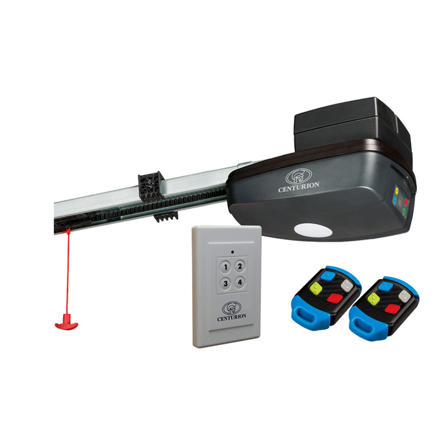
Please note that images in this installation manual are not to scale. 1. General Description The SDO4 has been designed to automate domestic garage doors safely, quietly and reliably. The product’s chain-driven system allows for whisper-quiet operation, while reliable battery backup ensures that the SDO4 will continue working even during lengthy power outages. In addition, the SDO4’s built-in collision sensing circuitry makes it a very safe automation solution. -
Page 9: Technical Specifications
Infrared safety beams (Optional, but recommended) Radio receiver Code-hopping 433MHz Receiver code storage 20 transmitters (consisting of four buttons each) capacity TABLE 1 1: Can operate off a solar supply, please consult Centurion Systems (Pty) Ltd for assistance 2: Requires infrared safety beams to be fitted 2.3. Fuse protection The following protection fuses are provided on the system: Item Type Rating Main controller... -
Page 10: Product Identification
3. Product Identification END A END B END B FIGURE 2. PRODUCT IDENTIFICATION 1. Control head unit 9. Drive chain 2. Rail 10. End stop 3. Release handle 11. Carriage 4. Straight towing arm 12. Chain bullet 5. Towing bracket 13. -
Page 11: Fasteners List And Spares
3.1. Fasteners list and spares Description Description ST5.5 x 50 Self-tapping Coach Screws M8 Wizzlock Nuts ST8 x 60 Self-tapping Screws Ø8 x 71 Clevice Pin ST6.3 x 25 Self-tapping Screws Ø8 x 18 Black Clevice Pin - Hex Flange Head Ø2 Hairpin Clips M6 x 8 Black Cross Pan Head Screws 12 x 60mm Fischer Plugs... -
Page 12: Preparation Of Site
5. Preparation of Site 5.1. General consideration for the installation Always recommend the fitment of additional safety equipment such as safety edges and safety beams, for additional protection against entrapment or other mechanical risks. Ensure that no pipes or electrical cables are in the way of the intended installation. Install the garage operator only if: •... -
Page 13: Operator Installation
6. Operator Installation 6.1. Assembly instructions 6.1.1. Identify the garage door type Identify the garage door type and then select the preferred installation method and assembly type that is best-suited to the application. Sectional doors • Use a 3000mm one-piece drive rail • The standard 3000mm drive rail will lift a door up to 2440mm high. - Page 14 6.1.2. General assembly M8 Nut M8 Gutter bolts Open the packing carton and expose the SDO4 components. Orientate the drive rail so that the End ‘A’ terminal bracket faces towards the garage door 1. Fit the M8 black gutter bolts onto the drive rail hanger.
- Page 15 4. Place the two U-Brackets into U-Brackets position over the four holes found on the head unit (Figure 9). 5. Secure the U-Brackets into position using 4x black M6x12mm screws supplied (Figure 10). FIGURE 9 M6x12mm Screws FIGURE 10 6.1.3. Tensioning the chain The chain comes pre-tensioned from the factory;...
-
Page 16: Installation Instructions
6.2. Installation instructions 6.2.1. Sectional doors (For Tip-up doors skip to Section 6.2.2) Before commencing the installation, ensure that you have carefully read and understood all safety recommendations. In particular, ensure that the installation of the garage door complies with the requirements specified. - Page 17 6.2.1.1. Mounting the header bracket The header bracket carries ALL of the opening and closing thrust of the SDO4 and as such must be securely fastened to a rigid, structural member of the garage. It is entirely up to the installer to determine the fixing method and the structural suitability of the fixing points.
- Page 18 Place the header bracket on the Hole A Hole B wall as shown in Figure 15. Ensure that the bottom edge of Hole C the bracket is level, and no more than 50mm above the highest Header bracket arcing point of the garage door. 0-50mm (Note the orientation) Mark the location of the four screw...
- Page 19 Small spirit Hammer level If after securing the header bracket, it is slightly out (not level), use a hammer to knock the tabs gently up or down with a small spirit level placed on top of them. Header bracket This will ensure a perfectly tabs level installation (Figure 18).
- Page 20 Circle Clip Header bracket Locate the long clevis pin through the holes and secure it into position with a supplied Circle Clip on the Clevis other end of the clevis pin. Dowel split pins have also been supplied should they be preferred over the use of the circle pin clips.
- Page 21 Spirit level SDO4 Use a long spirit level along the length of the SDO4 drive rail, and level out the SDO4, so that it is running parallel to the ceiling. FIGURE 24 Place another spirit level perpendicular to the ceiling, and line Structural Spirit level it up with the center of the drive rail member of ceiling hanger bolt on the side of the drive...
- Page 22 150mm length of punched angle iron Measure and cut a 150mm length of punched angle iron with a pair of tin snips. Snip off the four corners of the punched angle iron to add a degree of safety and neatness to the installation. FIGURE 27 Ceiling Punched angle iron...
- Page 23 Ceiling Mounted punched Level the SDO4 again, and measure angle iron the length needed from the ceiling Spirit level to the underside of the drive rail, marked as ‘Value Xmm’ in Figure 29. Drive Rail SDO4 FIGURE 29 Two equal lengths of punched angle iron Using an angle grinder or hack saw, l u e cut two lengths of punched angle iron to the measurement taken for...
- Page 24 M8 Flange bolts Punched angle iron Spirit level mounted Use a spirit level to ensure that to ceiling the SDO4 is still level and parallel to the ceiling. Align the holes of the punched angle iron mounted to the ceiling, with the holes on M8 Flange nuts the punched angle iron mounted to the drive rail hanger.
- Page 25 6.2.1.4. Mounting the towing bracket to the garage door. SDO4 Garage door Marked top edge of the top roller Garage door Close the garage door, and find center line Top roller its center line. Make a level mark perpendicular to the garage door center line, and in line with the top edge of the top roller of the garage door.
- Page 26 6.2.1.4. Fitting the bent towing arm to the towing bracket and straight towing arm. Towing Garage door bracket Bent towing Slot the bent towing arm between the two protruding tabs of the towing bracket, and align the holes. Note the orientation of the bent towing arm.
- Page 27 The two towing arms must be joined in such a way that they are just short of parallel to the garage door and the ceiling. Straight towing arm Angle ‘Z’ should be ±80° when the garage door Bent towing arm is in the closed position, as shown in Figure 41. This will put less strain on the motor on start-up and, furthermore, aid in SDO4...
-
Page 28: Tip-Up Doors
6.2.2. Tip-up doors Before commencing the installation, ensure that you have carefully read and understood all safety recommendations. In particular, ensure that the installation of the garage door complies with the requirements specified. Make any necessary adjustments to the garage door BEFORE commencing the installation! Important considerations Pivot... - Page 29 6.2.2.1. Mounting the header bracket The header bracket carries ALL of the opening and closing thrust of the SDO4 and as such must be securely fastened to a rigid, structural member of the garage. It is entirely up to the installer to determine the fixing method and the structural suitability of the fixing points.
- Page 30 Place the header bracket on the Hole A Hole B wall as shown in Figure 48. Ensure that the bottom edge of Hole C the bracket is level, and between 20mm - 50mm, but no more than Header bracket 50mm above the highest arcing 20-50mm (Note the orientation) point of the garage door.
- Page 31 Small spirit Hammer level If, after securing the header bracket, it is slightly out (not level), use a hammer to knock the tabs gently up or down with a small spirit level placed on top of them. Header bracket This will ensure a perfectly tabs level installation.
- Page 32 Circle Clip Header Locate the long clevis pin through bracket the holes and secure it into position with a supplied Circle Clip on the Clevis other end of the clevis pin. Dowel split pins have also been supplied should they be preferred over the use of the circle pin clips.
- Page 33 SDO4 Control Head Lift the SDO4 to a point where the control unit (Point B) is in line with the top of the open garage door Garage door (Point A). Point A in line with Point B FIGURE 57 Keeping the control unit in line with the top of the garage door, place a spirit level perpendicular to the ceiling, and line it up with the center...
- Page 34 150mm length of punched angle iron Measure and cut a 150mm length of punched angle iron with a pair of tin snips. Snip off the four corners of the punched angle iron to add a degree of safety and neatness to the installation. FIGURE 60 Ceiling Punched angle iron...
- Page 35 Ceiling Position the SDO4 again, as shown Mounted punched angle iron in Figure 60, and measure the length needed from the ceiling to the underside of the drive rail, marked as ‘Value Xmm’ in Figure 62. Drive rail SDO4 FIGURE 62 Two equal lengths of punched angle iron Using an angle grinder or hack saw, l u e...
- Page 36 Align the holes of the punched angle M6 Flange bolts Punched iron mounted to the ceiling, with angle iron Spirit level the holes on the punched angle iron mounted to ceiling mounted to the drive rail hanger. Secure it into position using two supplied M8 flange bolts and nuts with a 13mm socket.
- Page 37 6.2.2.4. Mounting the towing bracket to the garage door. SDO4 Garage door Garage door center line Close the garage door, and find its center line. FIGURE 67 Center the towing bracket on the garage door center line and so that Garage door the top edge of the towing bracket is as close to the top edge of the garage door as possible.
- Page 38 6.2.2.5. Fitting the bent towing arm to the towing bracket and straight towing arm. Towing bracket Garage door Slot the bent towing arm between the two protruding tabs of the towing bracket, and align the holes. Note the orientation of the bent towing arm.
- Page 39 The two towing arms must be joined in such a way that they are just short of parallel to the garage door and the ceiling. Straight towing arm Angle ‘Z’ should be ±80° when the garage door Bent towing is in the closed position, as shown in Figure 73. This will put less strain on the motor on start-up and, furthermore, aid in preventing the garage door...
-
Page 40: Engaging And Disengaging The Motor
6.3. Engaging and disengaging the motor • The unique engage / disengage mechanism provides positive garage door locking, even during power outages; Functionality • TO DISENGAGE - pull down on the release handle until you hear a ‘click’ • TO ENGAGE - Pull the release handle back towards the control head until you hear a ‘click’, and move the carriage until it engages with the chain bullet (Figure 76) • Never attempt to open or close the garage door by pulling on the release handle. -
Page 41: Positioning The Opening And Closing Limit Stoppers
If grub screws are not securely tightened, the end-stops will fail during setup. The grub screws will slightly dent the rail when tightened correctly. 6.4.2. Positioning the opening end-stop • Ensure that the motor is disengaged • Open the garage door fully •... -
Page 42: The Wireless Wall Switch
Mounting • The switch can be permanently screwed to the wall through Screw the mounting holes provided or alternatively ‘hooked’ on the wall, Wall switch Board front cover providing the convenience of easy demount ability, through the ‘hook’ holes provided on the base cover • To permanently mount the unit, Fischer open it, and place the back panel plug... -
Page 43: Connecting To A Power Supply
6.6.1.2. Connection • Strip back and connect the two strands of one end of the cable to each of the two terminals located on the outer cover of each safety beam • Fix the cable securely up and along the wall, and run one length of each cable adjacent to the control box •... -
Page 44: Defaulting The Sdo4
6.8. Defaulting the SDO4 Follow the below procedure to default the SDO4 to its factory settings. Please note that defaulting the SDO4 will clear its setting memory, therefore any operating parameters will be set to default values and Limits/Force settings are deleted. Remotes are NOT deleted. 1. -
Page 45: Electrical Setup
7. Electrical setup of accessories • Two out (Power) and two in (Trigger and Safety beams) terminals are provided to support the connection of the most common external accessories • The output terminals can be accessed by removing the screw above the control panel, and hinging down the power head cover (Item 4 - Figure 85). - Page 46 Transmitter Receiver Infrared beams FIGURE 82. WIRING TWO-WIRE SAFETY BEAMS TO THE SDO4 24V + Universal Hard-wired receiver wall switch FIGURE 83. WIRING A UNIVERSAL FIGURE 84. HARD-WIRING A WALL SDO4 SDO4 RECEIVER TO THE SWITCH TO THE page 46 www.centsys.com...
-
Page 47: Commissioning The System
8. Commissioning the system 8.1. Control box FIGURE 85 1. Yellow ‘+’ button, and Blue ‘-’ button. • In Standby: Decrease or increase force offset values Pressing ‘+’ and ‘-’ together: Enters Function Setup menu • • In Function Setup menu: Scroll functions and values • In Transmitter Setup menu: Scroll functions 2. -
Page 48: Setting The Limits
• “tu” if the unit is being installed on a Tip-Up door • “SE” if the unit is being installed on a Sectional door Press the “Green” Confirm button to select the correct option. 4. After door type has been selected, only L.L will be displayed. The dot in-between indicates that the door type has been selected. 5. To adjust the position of the door (after door type has been selected) the “+” can be used to move the door up and “-” to move the door down before initiating the limit setup. 8.3. Setting the limits Ensure that the Stoppers are correctly placed and tightened. Refer to Section 6.3. Modifying the position of the door. - Page 49 8.3.3.2. Set Safety Offset Value to Maximum • For installation where maximum power and less sensitivity is required – • Set the Safety Offset Value to “F5” • If F5 is still too sensitive, set Full power mode to On. Refer to menu With Safety Offset set to Maximum, the door is dangerous and it is recommended that Safety Beams be used.
- Page 50 9. Programming remote controls The SDO4 offers seven menu levels pertaining to six different functions that can be activated either via a handheld remote control or via the four-button wireless wall switch. Each menu level and function has a different effect upon the controller and the load which it controls. In addition, a seventh menu can be accessed which will learn the buttons of a four-button remote control or wall switch in the order described below. 9.1.
- Page 51 9.2.2. Light Function / Remote Learning. Learning a button to Function Two will enable that button to switch the courtesy light on and off, or learn in additional remotes. Operation • First Operation: Momentarily press the associated remote control button to either switch the courtesy light on or off. If the light has been switched on, it will time out as per the maximum current timer of 2 minutes. •...
- Page 52 Learning procedure Enter Learn mode (Refer 10.1). Using the ‘+’ and ‘-’ buttons, select ‘ao’. Press and hold the transmitter button until the display flashes “ao” and buzzer beeps four times. 9.2.5. Learn all buttons function If function five is selected, all the buttons of a remote control or wall switch will be learned in the following configuration and sequence: 1. Button 1 – Open/Stop/Close 2. Button 2 – Light 3. Button 3 – Lock 4. Button 4 – Autoclose override Operation The operation of Function Five will be according to the four different functions described previously. Learning procedure Enter Learn mode (Refer 10.1). Using the ‘+’ and ‘-’ buttons, select ‘bu’. Press and hold the transmitter button until the display flashes ‘bu’ and the buzzer beeps five times. 9.2.6.
-
Page 53: Wiring Safety Beams / Photocells
9.3. Deleting remote controls • Remote controls can be deleted at any stage Following this procedure will remove all remote controls and transmitters from the SDO4’s memory. 1. In standby mode (only a “.” [Dot] displayed on the LED Display), press the “Red” Learn button once. 2. The LED Display will display “00” to confirm that the user is in the programming menu. 3. Press and Hold green “Confirm” button until the Light Flashes; when the screen displays “dL”, all remotes have been successfully deleted. 1. With an empty memory, ‘00’ will be displayed, otherwise it will display the number of remotes learned into the system. www.centsys.com page 53... -
Page 54: Sdo4 Features
10. SDO4 Features 10.1. Menu Navigation map Default Menu Menu Description Value Description Value OF - Disable Safety Beam On - Enable Safety Beam in Closed Safety Photo Beam Direction 2d - Enable Safety Beam in Open and Closed Direction OF - Disabled Autoclose 05 - 5 sec / 30 sec 15 - 15 sec / 90 sec... - Page 55 10.1. Safety Beams (Sb) The installation of safety beams greatly enhances safety by constantly monitoring for persons or objects which may pass within the path of the moving garage door. Safety Beam Menu (Sb) has the following settings: • OFF - Safety Beams are disabled • ON - While closing, the door will stop and re-open if the Safety Beams are triggered •...
- Page 56 If the SDO4 is triggered while in Shutdown Mode, the Buzzer will beep three times to indicate Shutdown Mode and the operator will not operate 10.4.3. Solar power • A n optional solar power kit is available. Some modifications may be necessary. Contact Centurion Systems (Pty) Ltd for further information 10.4.4. Warning buzzer • An audible buzzer will; •...
- Page 57 10.7. Soft Start When commencing movement from any stationary position, the SDO4 will slowly ramp up to full speed. This is in order to minimise start-up load on the SDO4 and garage door and provide smooth and quiet operation. 10.8. Slow Stop (SS) By intelligently reducing the speed of the garage door as it approaches a limit point, the SDO4 ensures quieter garage door closing and prolongs SDO4 and garage door life.
- Page 58 11. Troubleshooting If an error occurs, the courtesy LED will triple flash and an error code will be displayed on the screen. Error code Description Possible Solution Align Safety Beams, Check connections, select two-wire or Safety Beam Active four-wire safety beams with corresponding jumper. Safety Strip Advice This is not applicable to SA operators. Check door tension Door Imbalanced (Door Service monitor).
- Page 59 4. Has been repaired by any workshop and / or person NOT previously authorised by the manufacturer. 5. Has been repaired with components not previously tested, passed or authorised by Centurion Systems (Pty) Ltd, South Africa or one of its subsidiary companies. www.centsys.com page 59...
-
Page 60: Installation Handover
Centurion Systems (Pty) Ltd does not accept any liability caused by improper use of the product, or for use other than that for which the automated system was designed. - Page 61 Notes www.centsys.com page 61...
- Page 62 Notes page 62 www.centsys.com...
- Page 63 Notes www.centsys.com page 63...
- Page 64 South Africa and/or other countries, in favour of Centurion Systems (Pty) Ltd, South Africa. The CENTURION and CENTSYS logos, all product and brand names in this document that are accompanied by the TM symbol are trademarks of Centurion Systems (Pty) Ltd, in South Africa and other territories; all rights are reserved. We invite you to contact us for further details.
Need help?
Do you have a question about the SD04 and is the answer not in the manual?
Questions and answers