Table of Contents
Advertisement
Advertisement
Table of Contents

Related Manuals for Centurion CS32 RDO


Summary of Contents for Centurion CS32 RDO
- Page 1 INSTALLATION MANUAL...
-
Page 2: Important Safety Recommendations
IMPORTANT SAFETY RECOMMENDATIONS FAILURE TO COMPLY WITH THE FOLLOWING SAFETY RECOMMENDATIONS MAY RESULT IN SERIOUS PERSONAL INJURY, DEATH AND/OR PROPERTY DAMAGE READ AND FOLLOW ALL SAFETY AND INSTALLATION INSTRUCTIONS CAREFULLY. The installation of your new Automatic Garage Door Opener (herein after referred to as “RDO”) must be carried out by a technically qualified or licensed person. - Page 3 IMPORTANT SAFETY RECOMMENDATIONS Never use the RDO unless the Garage Door is in full view and free from objects such as cars, children and/or adults. Never allow children to operate the RDO. 17. Never operate the RDO when children/persons are under or near the path of the door. Children must be supervised at all times when near the Garage Door and when the RDO is in use.
- Page 4 Has damage caused as a result of handling during transit, atmospheric conditions, insect infestation, power surges or other forces outside our control. Has been repaired by any workshop and / or person NOT previously authorised by CENTURION SYSTEMS. Has been repaired with components not previously tested, passed or authorised by...
-
Page 5: Operating Controls
OPERATING CONTROLS OPERATING CONTROLS Fig 1 Fig 1A Fig 2 Fig 2A Fig 3 Fig 3A... - Page 6 OPERATING CONTROLS INFRARED SAFETY BEAM ENABLE DIP SWITCH. ( refer Sec.18 ) AUTO CLOSE ENABLE DIP SWITCH. (refer Sec.21) AUTO CLOSE DELAY DIP SWITCHES are used to adjust the time to auto close. (refer Sec.21) SAME AS ABOVE CODE BUTTON used for storing or erasing transmitter security code (refer Sec.15) (Does not apply if kit supplied with NOVA VOYAGER...
-
Page 7: Requirements Prior To Installation
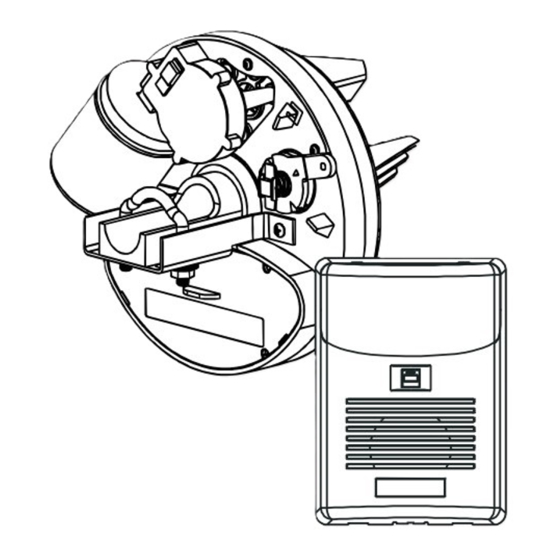
REQUIREMENTS PRIOR TO INSTALLATION Forward Your RDO is comprised of 2 major individual components being, Drive Unit (top figure alongside) and Control Box (bottom figure alongside). This section of the manual deals with the basic fitting requirements which should be met before you attempt to install your opener. - Page 8 REQUIREMENTS PRIOR TO INSTALLATION Check For Correct Function Of The Door Before beginning the installation of the RDO check that the garage door is functioning correctly. The garage door must be well balanced and operate smoothly and freely. When opened to between 900~1200mm from the floor and released the garage door should remain in one fixed position and not r i s e or fall more than 100mm.
-
Page 9: Battery Charger
REQUIREMENTS PRIOR TO INSTALLATION Battery Charger The plug-in battery charger is provided to keep the batteries charged to an optimum voltage. A red coloured LED, located on the charger casing will illuminate to indicate that the charger has been connected to an active power supply. Important Note: Do not mount the charger any further away from the control box than the connection cable allows. - Page 10 INSTALLATION INSTRUCTIONS 2. Fitting Of Drive Unit To The Door (Right Hand Installation Depicted) 2.1 Check that the door U-bolt is securely tightened on the opposite end of the door to which the Drive Unit will be fitted (Fig.7) 2.2 Open the door fully and ensure that the bottom stoppers of the Garage Door are engaged with the stoppers on the door guide tracks.
- Page 11 INSTALLATION INSTRUCTIONS Fig 9 Fig 10 Adjusting Release Cord 3.1 Unfurl the Red Disengage Cord and cut it to an appropriate length so that its end hangs approximately 1800mm above the garage floor. Engaging And Disengaging The Drive Unit 4.1 To disengage the Drive Unit from the garage door pull down on the Red Release Cord. (Fig.11) 4.2 To engage the Drive Unit to the garage door pull down once more on the Red Release Cord.
-
Page 12: Settings And Adjustments
INSTALLATION INSTRUCTIONS 6.2 With the garage door in the fully closed position, mark the curtain at points “A” and “B” as depicted in Fig.13 6.3 Once marked, open the door slightly so as to have access to the marked positions. Secure the curtain to the drum wheel ensuring that the fixing points are at least 90 degrees apart. -
Page 13: Connecting To Power Supply
SETTINGS AND ADJUSTMENTS 8.3 Rotate the Close Limit (Upper) Cam (Item 14, Fig 15) by hand, in the direction of the Close Limit (Upper) Switch, until you hear the Switch “click”. Once the Open Limit Switch “clicks” continue to rotate the Cam a further 10 degrees or so towards the switch. - Page 14 SETTINGS AND ADJUSTMENTS Safety Obstruction Force Adjustment – Open Direction 12.1 Locate the Open force setting (UP) thumb screw and turn it to the maximum setting in a clockwise direction. (Upper of 2 screws – refer figure below) 12.2 With the garage door in the fully CLOSED position - press the red button located on the face of the Control Box.
-
Page 15: Wall Switch Installation
SETTINGS AND ADJUSTMENTS 14.2 As the garage door is opening push down firmly on the bottom rail of the door (middle of the door from the inside) Open force setting Confirmation LED Learn Close force setting Operate Button Transmitters Code Learning Note: If the RDO kit has been supplied with a separate NOVA VOYAGER receiver module, please follow the instructions provided with this receiver for learning the transmitters, otherwise proceed as follows:... - Page 16 SETTINGS AND ADJUSTMENTS 17.3 Connect the 2 strands on the opposite end of the cable to the terminals located on the back of the Wall Switch. 17.4 Important Note: The Wall Switch must be mounted within sight of the door and a reasonable distance away from moving parts.
-
Page 17: Auto Close Mode
SETTINGS AND ADJUSTMENTS Safety Beams - Alignment 19.1 Align the 2 Safety Beams (by turning the mounting bracket) so that their lenses are aimed directly at each other. A red indicator lamp on the “receiver” will glow solid once correct alignment has been achieved. 19.2 Test the Safety Beam alignment several times, each time ensuring that when the Safety Beams are obstructed the red indicator lamp is extinguished, and when unobstructed the indicator lamp glows solid. -
Page 18: Troubleshooting Guide
TROUBLE SHOOTING TROUBLE-SHOOTING GUIDE SYMPTOM POSSIBLE CAUSES REMEDY Mains power not turned on Turn on mains power Door will not operate Door is obstructed Remove obstruction Door is locked or Mechanical door lock has been Unlock door motor jammed engaged Inspect door and remove jam Door will not reverse Safety Obstruction Force setting is too... - Page 19 CONTROL BOX MOUNTING TEMPLATE...
- Page 20 Centurion Systems (Pty) Ltd Head Office: Tel: +27 (0)11-699-2400, Fax: +27 (0)11-704-3412 or (0)11-462-6669 (Omit (0) when dialing from outside South Africa) 148 Epsom Avenue, North Riding P.O. Box 506, Cramerview, 2060 South Africa Sharecall 0860-CENTURION (Sharecall number applicable when dialed from within South Africa only) or visit www.centsys.co.za...
Need help?
Do you have a question about the CS32 RDO and is the answer not in the manual?
Questions and answers
What is the problem when the lamp indicate of centurion 9RDO garage door opener when is changing?