2N VoiceBlue Next User Manual
Hide thumbs
Also See for VoiceBlue Next:
- User manual (117 pages) ,
- Installation manual (9 pages) ,
- Quick manual (3 pages)
Table of Contents
Advertisement
Quick Links
Download this manual
See also:
User Manual
Advertisement
Table of Contents

Related Manuals for 2N VoiceBlue Next


Summary of Contents for 2N VoiceBlue Next
- Page 1 ® VoiceBlue Next User Manual Version www.2n.cz Firmware 01.00.04...
- Page 2 1999/5/EC directive. For the full wording of the Declaration of Conformity see the CD-ROM enclosed and at www.2n.cz. The 2N TELEKOMUNIKACE company is a holder of the ISO 9001:2000 certificate. All...
-
Page 3: Table Of Contents
Table of Contents 1. Product Overview............... 7 Product Description ....................... 8 ® VoiceBlue Next Basic Features ................8 Safety Precautions ......................9 Firmware Upgrade ......................10 Terms and Symbols Used ................... 11 Symbols in Manual ......................11 Future Functions, Innovations ..................11 2. - Page 4 Point-to-Multipoint Configuration ..................33 ® 3. 2N VoiceBlue Next Configuration ......... 35 Factory Reset ........................ 36 Basic Configuration – Step by Step ................37 Call Routing ........................39 Mobility Extension ......................39 LCR Table ........................40 Routing Algorithm for Outgoing Calls ................41 Routing Algorithm for Incoming Calls ................
- Page 5 5. Technical Parameters ............85 Technical Parameters ....................86 6. Supplementary Information ..........89 Regulations and Directives ..................90 Troubleshooting ......................91 List of Abbreviations ....................92 General Instructions and Cautions ................94 Electric Waste and Used Battery Pack Handling ............95...
-
Page 7: Product Overview
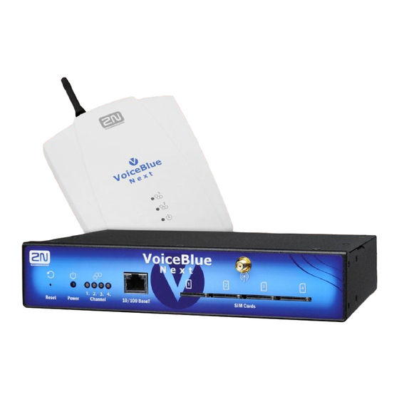
Product Overview ® In this section, we introduce the 2N VoiceBlue Next product, outline its application options and highlight the advantages following from its use. This section also includes safety instructions. Here is what you can find in this section: Product Description ... -
Page 8: Product Description
® Ethernet, connect an antenna and insert the SIM card. 2N VoiceBlue Next can be combined with the 2N Mobility Extension service (remote GSM extension) for up to 8 ® ® users . -
Page 9: Safety Precautions
Safety Precautions 1.2 Safety Precautions It is prohibited to use any transmitters, including the UMTS/GSM devices, in areas where explosives are used, such as quarries. It is prohibited to use the GSM gateways at petrol stations where mobile telephones are also prohibited. GSM phones may affect sensitive life-saving devices in medical centres. -
Page 10: Firmware Upgrade
The manufacturer reserves the right to modify the product in order to improve its qualities. In response to the customers‟ requirements, the manufacturer constantly improves ® the software contained in the product (firmware). For the latest 2N VoiceBlue Next firmware version and the User Manual refer to the 2N sites. -
Page 11: Terms And Symbols Used
Terms and Symbols Used 1.4 Terms and Symbols Used Symbols in Manual Safety Warning Always abide by this information to prevent injury of persons. Warning Always abide by this information to prevent damage to the device. Caution Important information for system functionality. ... -
Page 13: Description And Installation
Description and Installation ® This section describes the proper 2N VoiceBlue Next product installation and connection. Here is what you can find in this section: Before You Start Factory Settings Brief Installation Guide IP Voice Transmission ... -
Page 14: Before You Start
Make sure that you are equipped with all system components necessary ® for putting 2N VoiceBlue Next in operation (SIM card, VoIP phone and/or duly configured SIP line of your SIP Proxy, an available 100BaseT socket and a PC for initial settings). Product Completeness Check ®... -
Page 15: Connector Lay-Out (4-Channel Version)
Find a power supply connector (DC Jack 2.1mm) and type plates at the rear. Status LED Indicators ® The 2N VoiceBlue Next states are indicated by LEDs on the front and system connector sides. For the LED types see the table below. -
Page 16: Sim Card Placement (2-Channel Version)
10BaseT Ethernet connected, no operation Green flashing / Orange shining 10BaseT Ethernet connected, network operation SIM Card Placement (2-Channel Version) ® Lift off the SIM card holder on the 2N VoiceBlue Next backside, insert the SIM card and replace the holder, securing the latch. -
Page 17: Sim Card Placement (4-Channel Version)
Before You Start SIM Card Placement (4-Channel Version) ® Insert a SIM card into one of the four SIM holders on the 2N VoiceBlue Next front making sure that the chip contacts are at the front bottom. The SIM holders are equipped with the push&pull technology for facilitation. -
Page 18: Gsm/Umts Network Restriction
Contact your dealer please for more information. Potential GSM/UMTS Troubles All 2N GSM gateways work reliably under a long-time full load. The following problems may be caused by GSM/UMTS networks: GSM/UMTS module(s) cannot log in, log in slowly, or log out occasionally. This problem may be caused by any of the following situations: ... -
Page 19: Factory Settings
Factory Settings 2.2 Factory Settings The table below includes the factory settings for the key configuration parameters of the GSM gateway: Parameter Value IP address 192.168.1.2 IP mask 255.255.255.0 IP gateway 192.168.1.1 Username Admin Password Caution Remember to change the username and password during the first ... -
Page 20: Brief Installation Guide
VoiceBlue Next may not be exposed to aggressive gases, acid and solvent vapours, and so on. ® VoiceBlue Next is intended for indoor use. It may not be exposed to rain, flowing water, condensing moisture, fog, and so on. ®... - Page 21 Brief Installation Guide ® No strong electromagnetic radiation is allowed on the 2N VoiceBlue Next installation site. ® No strong electromagnetic reflections are allowed on the 2N VoiceBlue Next antenna installation site. ® An inappropriate location of 2N VoiceBlue Next or its antenna close to ...
-
Page 22: Wall Mounting (2-Channel Version)
Horizontal Mounting (4-Chanel Version) ® VoiceBlue Next is ready for mounting on a horizontal support. You can stick rubber feet (included in the delivery) on the device if necessary. Follow the instructions below: 1) Put the GSM gateway carefully on a stable horizontal support with its bottom side up. -
Page 23: System Rack Mounting (4-Channel Version)
Brief Installation Guide System Rack Mounting (4-Channel Version) ® VoiceBlue Next can be mounted into a system rack. Purchase the rack accessories separately under Part No. 5051099E. The accessory pack includes the following components: Components Pieces Short wing Long wing... - Page 24 Brief Installation Guide Pair Mounting Follow the instructions below to rack mount two GSM gateways into one 1U place: 1) Put the GSM gateways next to each other making their sides touch each other. Fit the short wings (included in the package) onto the free gateway ends with the screws enclosed.
-
Page 25: Power Supply Connection
Brief Installation Guide 3) Place the GSM gateway pair into a free 1U place in the system rack and fit it with four rack screws (included in the package). Caution The rear and upper connecting plates have different holes – the upper ... -
Page 26: Antenna Connection
Feeding the device without antenna connection may result in the GSM module transmitter damage. Antenna Connection ® VoiceBlue Next is equipped with a SMA female antenna connector for all the GSM/UMTS modules. The external antenna should always be installed vertically on a site with a good wireless signal. Warning Tighten the antenna connector gently with your hand –... -
Page 27: Antenna Splitter
No antenna splitter is used for one-channel 2N VoiceBlue Next gateways. Licence Restrictions ® VoiceBlue Next may contain time limited software licences. See p. 17 for more information. Firmware Upgrade ® Please upgrade the 2N VoiceBlue Next firmware before installing the system. Check www.2N.cz... - Page 28 Click on Upgrade, then on Browse and select the new firmware file. Click on the Download firmware icon in the lower part of the web page. ® VoiceBlue Next will upgrade the firmware automatically. ...
-
Page 29: Ip Voice Transmission
® During call set-up, a codec is selected automatically for voice transmission. 2N VoiceBlue Next supports the codecs included in the table above. The type of codec to ® be used depends on your VoIP network (individual devices) and your 2N VoiceBlue ®... -
Page 30: Sip Components
® The 2N VoiceBlue Next VoIP-GSM gateway acts as a UA in any case (has the same functions as a VoIP phone), i.e. receives call set-up requirements and, on the basis of its inner LCR table, routes calls to GSM networks. - Page 31 IP Voice Transmission The answers to the SIP messages are numerically coded as the case is with the http protocol. Below are the most important ones: 1XX – information messages (100 – trying, 180 – ringing, 183 - progress); ...
-
Page 32: Voiceblue Next Connection To Voip
SIP Phones Point-to-Point Configuration ® VoiceBlue Next can communicate with just one SIP VoIP phone or device (a VoIP gateway, e.g.) in the PTP (Point-to-Point) mode. The IP address of the opposite party ® is always selected as the Proxy server IP address in 2N VoiceBlue Next for this mode. -
Page 33: Point-To-Multipoint Configuration
Multiple source devices (VoIP phones, e.g.) and multiple target devices (2N VoiceBlue Next, e.g.) can be used in this mode. An internal routing algorithm (Least Cost Router, LCR) of your SIP Proxy is used for routing outgoing GSM and other calls ®... -
Page 35: Voiceblue Next Configuration
® VoiceBlue Next Configuration ® This section describes the 2N VoiceBlue Next configuration. Here is what you can find in this section: Factory Reset Basic Configuration – Step by Step Call Routing Web Configuration Interface ... -
Page 36: Factory Reset
Factory Reset 3.1 Factory Reset If you forget the password or set the IP interface incorrectly, you can press the RESET button to the right of the RJ45 Ethernet connector for a long time. Doing this, you restore the factory default configuration values for all parameters, including the Ethernet interface parameters and access data. -
Page 37: Basic Configuration - Step By Step
3.2 Basic Configuration – Step by Step ® This section will help put your 2N VoiceBlue Next gateway in operation for the first time. Refer to all S. 3 subsections for detailed settings. Install the GSM gateway as instructed in Subs. 2.3. Before the first start, ... - Page 38 Should you get in troubles, follow the steps below please: Read the User Manual carefully and check all parameters. Find answers to the frequently asked questions at http://faq.2n.cz. Consult your servicing partner. You are recommended to attend a 2N certified training to improve your installation chances.
-
Page 39: Call Routing
Call Routing 3.3 Call Routing Calls from a VoIP port to a GSM/UMTS network are routed to any GSM/UMTS port according to the LCR (Least Cost Routing) table. If an incoming call is routed via a busy port, other ports are checked automatically for availability (depending on the configuration) and in case no allowed outgoing port is available, the outgoing call is rejected. -
Page 40: Lcr Table
Line 222 Model situation description: A client is calling Mr. Green at 2N from his or her fixed line. According to the company PBX configuration, all calls to line 111 (Green‟s office phone) automatically alert line 333 too (red arrows). Suppose Mr. Green is on a business trip. The GSM gateway automatically forwards the call to Mr. -
Page 41: Routing Algorithm For Outgoing Calls
The GSM/UMTS outgoing call routing algorithm is launched whenever the SIP Proxy ® ® routes an outgoing call to 2N VoiceBlue Next. Outgoing calls are routed via 2N VoiceBlue Next as follows: The calling subscriber dials the subscriber number and the SIP Proxy routes it ... -
Page 42: Routing Algorithm For Incoming Calls
® send either a voice message or the dialtone to the caller. After that, 2N VoiceBlue Next awaits the required count of digits necessary for connection set-up. Set the minimum and maximum counts of DTMF digits in the GSM incoming groups menu. - Page 43 Call Routing Dialing number from GSM GSM incoming groups table Reject Ignore GSM incoming Report to PC + Other incoming incoming groups table Voice message calls calls Callback activated Callback CLIP present in callback table Callback Ignore Reject deactivate Hang up + Mobility Extension deactivated or Dialing to GSM...
-
Page 44: Disa Welcome Note
Call Routing DISA Welcome Note If the DISA service is active and a welcome note has been recorded, the welcome note is played to every incoming call whose number is not included in the CLIP table or forwarded according to the Dynamic CLIP routing table. When the welcome note has been played, the gateway waits for the first DTMF digit for the period set in the GSM incoming groups - DTMF dialling timeout table. -
Page 45: Web Configuration Interface
3.4 Web Configuration Interface Essential Data ® The 2N VoiceBlue Next web interface supports the following web browsers: MS Internet Explorer v9 Mozilla Firefox v4 and higher Any other web browsers may cause troubles. The recommended screen resolution is 1280x1024 and colour quality 32bit or higher. The configuration interface is available in the English language version only at present. -
Page 46: Web Icons
Web Configuration Interface Caution You are recommended to change the initial login data upon your first login to considerably increase your system security. Web Icons Icon Description Reset factory values Store current configuration into GSM gateway Restore previous GSM gateway configuration values Save onto local disk of connected terminal Refresh display data Confirmation (e.g. -
Page 47: Gateway
Web Configuration Interface Restart for software restart of the GSM gateway. ® SIM client for gateway settings for connection to the 2N SIM Star system. SMS for receiving/sending SMS via the web interface. Utils including extending system tools (Ethernet tracing). - Page 48 Web Configuration Interface Firmware / Licence This window provides information on the gateway licensing, firmware and bootware versions and Ethernet interface MAC address. A new licence code can be inserted here. Firmware version - current firmware version of the gateway connected. ...
- Page 49 Web Configuration Interface Voice messages This window is used for recording, checking and downloading voice messages. LOG file The LOG file window helps read out the gateway LOG file. The bottom part of the window includes icons for saving the LOG file into a file and refreshing the LOG listing in the web window.
- Page 50 into the CDR file. ® Gateway ID - identifies 2N VoiceBlue Next numerically in the CDR in case multiple devices generate the CDR in the network. Summer / winter time Automatically switch to summer/winter time - enable an automatic change of ...
- Page 51 Web Configuration Interface Mobility Extension (DTMF settings) Start dialling (quick call forwarding) - DTMF code for quick forwarding start. End dialling (quick call forwarding) - DTMF code for quick forwarding end. Hold call - DTMF code for active call holding. ...
- Page 52 Web Configuration Interface ® Send 200 OK on REGISTER request – virtual registration of the device in 2N VoiceBlue Next (necessary for registration-requiring equipment). Replace CLIP from GSM with Caller ID. Deny DTMF according to RFC2833. Forward DTMF for ME (Mobility Extension).
- Page 53 ® Refer to Subs. 4.2, p. 69 for easy tracing through 2N VoiceBlue Next. Tones generated to VoIP Ring tone to VoIP – generate a ringing tone of your own, or transmit a real ...
- Page 54 Web Configuration Interface the call automatically and attempts to set it up through the next available outgoing group (as defined in the LCR table). Frequency 1;2;3;4 – defined frequency of the tone to be detected. Sequence list – sequence of the above defined tones for detection. ...
- Page 55 Web Configuration Interface Conversion table: ISDN Description Description cause code value Unallocated number Gone No route to destination Not found Channel unacceptable Service unavailable Normal call clearing User busy Busy here No user responding Temporarily unavailable No answer from user Temporarily unavailable Call rejected Decline...
- Page 56 GSM outgoing groups ® VoiceBlue Next allows you to work with two groups of outgoing calls for each of which you can set variable connection set-up modes and count of used minutes and sent SMS messages for a selected period.
- Page 57 Web Configuration Interface BTS lock – identify the BTS to which the GSM modules should be logged fixedly. Restart the selected GSM modules to execute the changes. Caution The BTS lock service works with specific GSM modules only (Q55)! ...
- Page 58 Web Configuration Interface Note Check the GSM/UMTS searching priorities on the SIM card using your mobile phone before enabling roaming. Caution Calls via a roaming network may increase you telephone bill! CLIR – fill in this parameter to define whether or not the called subscriber ...
- Page 59 GSM/UMTS provider‟s free minute/SMS limits are exceeded. GSM incoming groups ® VoiceBlue Next allows you to work with two groups of incoming calls for each of which you can set variable connection set-up modes. General settings Mode – set how the gateway should process incoming GSM calls: ...
- Page 60 Web Configuration Interface Report to PC + voice message – the GSM gateway sends information on incoming calls to a PC equipped with the call routing software. The DTMF dial-in with a voice welcome note can be activated for incoming calls.
- Page 61 Web Configuration Interface Others Time to keep CLIP in table – set the time for which records are to be kept in the AutoCLIP routing table. Add record only for unconnected call – unconnected outdoing calls are stored in the AutoCLIP table only.
- Page 62 Web Configuration Interface LCR table The LCR (Least Cost Routing) table helps route calls according to the called number and depending on the day time and weekday. Prefix list – select a list of prefixes to be used for the selected LCR row. ...
- Page 63 DHCP server are displayed in the IP address, Subnet mask and Default gateway items. Login configuration ® The window helps you set the access password and name for the 2N VoiceBlue Next web interface. Use the same data for Telnet connection too. Caution Remember to change the username and password during the first ...
-
Page 64: Utils
The file format is CFG-M202-gateway_serial_number-rrrrmmdd- hhmmss.tar. Configuration upload ® The window helps you upload new configuration settings into 2N VoiceBlue Next configuration. The Ethernet interface and login data remain the same! Warning Be sure to upload the configuration file intended for the selected GSM ... -
Page 65: Update
Restart ® This subsection provides information on a forced restart of 2N VoiceBlue Next. SIM client ® This section is displayed for those GSM gateways only that support the 2N SIM Star system connection – remote SIM card function. -
Page 67: Terminal
Terminal ® This section describes communication with 2N VoiceBlue Next using a terminal. Here is what you can find in this section: Terminal-Based Communication AT Interface LOGs CDRs Available Status Messages Statistics Tracing ... -
Page 68: Terminal-Based Communication
GSM gateway rejects the connection. Terminal ® VoiceBlue Next acts as an ANSI terminal with echo. Text commands are entered in one of the following formats: AT[command]<CR>, or AT[command]<CR><LF>. The answer consists of up to several rows, an empty row with <CR><LF> and the reply type: OK, ERROR, or BUSY. -
Page 69: At Interface
AT Interface 4.2 AT Interface ® VoiceBlue Next uses the list of AT commands derived from the standard AT set for configuration and monitoring purposes. The configuration entering commands start with AT%parameter_id. The configuration writing out commands start with AT§ion. -
Page 70: Configuration Commands
AT Interface AT&CR Call file listing and deleting (PRIGW awaits pressing of the # key to delete this line /with call info/ from memory and sends next line) Configuration commands Status Information AT&V Overview of all system settings AT&VI Overview of ISDN PRI settings AT&V0 Overview of basic GSM settings AT&V#... - Page 71 AT Interface mode – algorithm (0-none, 1-semiduplex, 2-fullduplex) atms,atfs – transit, receive gain (3=+5dB, 1=+2.5dB, 0=0dB, 2=-2.5dB, 4=-5dB AT%G02=mode,atms,atfs Voice processing settings (for TC35 GSM modules only) mode – algorithm (2-echo canceller) atms,atfs – transit, receive gain (3=+5dBm, 1=+2.5dB, 0=0dB, 2=-2.5dB, 4=-5dB AT%G06=mmdd,…mmdd…...
- Page 72 AT Interface 00..31 from GSM No. 32 first incoming calls from GSM AT!D Terminates call on AUX interface Trace Trace can be activated for only one session at a time AT!RE Start tracing of error messages on active interface AT!Lx Start tracing of LAN &...
- Page 73 AT Interface confirmations saved on SIM card. Possible answers:: *smserr (busy,list) or *smsinc (ix=1..255) for each saved SMS or status SMS , end of list or empty SIM card - *smsinc (ix=0). AT^SR=ch.ix SMS read - request for reading of an SMS message or SMS status saved on SIM card.
-
Page 74: Logs
For the current LOG records see the Gateway / Gateway control – LOG file section or use the AT&L AT command for Telnet sessions. The following list of LOG statuses is ® universal and some LOGs may not be included in 2N VoiceBlue Next: Type... - Page 75 LOGs H: repeated DM Repeated unsuccessful send of packet DM I: failed (TIMREC) Unsuccessful breaking-up of status TIMREC J: N(R) error Received wrong value N(R) – numbering of packets K: recv.FRMR Received packet FRMR (information about error) L: undef.frame Received packet of unknown type M: (I field) Received wrong I-packet (numbered packet) N: frame size...
-
Page 76: Cdr
4.4 CDR For the current CDRs see the Gateway / Gateway control – CDR file section or use the AT&C / AT&CR AT commands for Telnet sessions. 31.07.02/11:07:53 O-OK CAU-016 aux/g02 GRP-1 0:23 001:40 00000.00 0608218005 45456060 1/8942019636000065750 Column 1: ** ... -
Page 77: Available Status Messages
Available Status Messages 4.5 Available Status Messages The following list of statuses is universal and some messages may not be included in ® VoiceBlue Next. GSM Layer Statuses GSM Layer 2 Name Description What Follows INIT GSM module initialisation start... -
Page 78: Link Layer Statuses
Available Status Messages CPRES Indication of call from GSM (from Layer 2) CRECV Call from GSM is ringing on ISDN interface IPROC Call from GSM is processed by ISDN interface ACTIVE Connected call DISREQ Disconnection request (to Layer 2) DISIND Indication of disconnection (from Layer 2) RELREQ Module release for another call (to Layer 2) -
Page 79: Records Of Events And Calls
Available Status Messages Name Description LOGOUT User logged-out LOGIN User is entering name PASSW User is entering password IDLE User logged-in Records of Events and Calls Record Type in Log File Name Description POWER System power on, power off or reset INIT Initialisation of EEPROM (configuration) or Flash (upgrade) HW-ERR... -
Page 80: Statistics
Statistics 4.6 Statistics The GSM gateway automatically generates statistic data on all outgoing and incoming calls. These data can be deleted on the user level or though configuration (automatic deletion on a selected day). Explanation of columns: Pri/grp : type of calls Reset : date of last reset of the statistics Minutes : number of minutes Hhhh:mm:ss : same number converted to time... - Page 81 Statistics ------------------------------------------------------------------------------ #g1 out ( 2.01) 0:00:00 #g2 out ( 2.01) 0:00:00 module (reset) minutes hhhh:mm:ss calls reject failed c.offs smses ------------------------------------------------------------------------------ #m0 out ( 2.01) 0:00:00 #m1 out ( 2.01) 0:00:00 [Statistics of calls on module #0] sim/dir net/grp minutes hhhh:mm:ss calls reject failed c.offs smses ------------------------------------------------------------------------------ #1 inc 0:00:00...
-
Page 82: Tracing
4.7 Tracing ® VoiceBlue Next allows for operation tracing (VoIP, SIP, GSM). Tracing is accessible in one session only at a time, the other tracing requests are rejected with BUSY. With regard to a rather extensive volume of data, we recommend that the Write communication into file function should be activated before tracing. -
Page 83: External Sms Control
External SMS Control 4.8 External SMS Control If this function is enabled for the active Telnet session, the GSM gateway automatically sends information on an incoming SMS message. An SMS message can also be sent using special commands. Command Description „basic keep alive‟... - Page 84 External SMS Control Information Messages Message Description *smsinc: ch,ix,sts,mem An SMS message was received and saved into the SMS storage. *smsrep: ch,ix,sts,mem An SMS status confirmation was received. *smsout: ch[/id],ref,req An SMS message was sent and not saved into the SMS storage. *smspdu: ch,ix,sts,len,pdu,csum Content of SMS message or status confirmation.
-
Page 85: Technical Parameters
Technical Parameters ® This section provides the technical parameters of 2N VoiceBlue Next. -
Page 86: Technical Parameters
Technical Parameters 5.1 Technical Parameters Two-Channel Version Dimensions (W x H x D) 170x130x45 mm Power Supply Type External power adapter (SELF type) 90-230V,50-60Hz to 12V DC 2A Power over Ethernet (PoE 802.3af) Connector DC Jack 2.1mm Power input Up to 20W Interface Protocols TCP,UDP,IP,RTP,TELNET,http,DHCP... - Page 87 Technical Parameters Four-Channel Version Dimensions (W x H x D) 220x45x140 mm Power Supply Type External power adapter (SELF type) 90-230V,50-60Hz to 12V DC 2A Power over Ethernet (PoE 802.3af) Connector DC Jack 2.1mm Power input Up to 20W Interface Protocols TCP,UDP,IP,RTP,TELNET,http,DHCP Connector...
-
Page 89: Supplementary Information
Supplementary Information ® This section provides supplementary information on 2N VoiceBlue Next. Regulations and Directives Troubleshooting List of Abbreviations General Instructions and Cautions ... -
Page 90: Regulations And Directives
Regulations and Directives 6.1 Regulations and Directives ® VoiceBlue Next conforms to the following directives and regulations: Directive 1999/5/EC of the European Parliament and of the Council, of 9 March 1999 – on radio equipment and telecommunications terminal equipment and the mutual recognition of their conformity Directive 2006/95/EC of the European Parliament and of the Council ... -
Page 91: Troubleshooting
2N VoiceBlue Next is disconnected from the power supply. ® VoiceBlue Next fails to log in to the GSM network. Check the SIM card. Check the PIN. Check the antenna connection. Select a place with a good GSM signal. -
Page 92: List Of Abbreviations
List of Abbreviations 6.3 List of Abbreviations API (Application Programming Interface) ASR (Answer Seizure Ratio) BIOS (Basic Input-Output System) CD (Compact Disc) CDR (Call Data Record) CLIR (Calling Line Identification Restriction) COM (PC serial interface) ... - Page 93 List of Abbreviations SIP (Session Initiation Protocol) SMS (Short Message Service) SSH (Secure Shell) SW (Software) TCP (Transmission Control Protocol) UCMD (UDP commands) UDP (User Datagram Protocol) UMTS (Universal Mobile Telecommunication System) UPS (Uninterruptible Power Supply) ...
-
Page 94: General Instructions And Cautions
General Instructions and Cautions 6.4 General Instructions and Cautions Please read this User Manual carefully before using the product. Follow all instructions and recommendations included herein. Any use of the product that is in contradiction with the instructions provided herein may result in malfunction, damage or destruction of the product. -
Page 95: Electric Waste And Used Battery Pack Handling
General Instructions and Cautions Electric Waste and Used Battery Pack Handling Do not place used electric devices and battery packs into municipal waste containers. An undue disposal thereof might impair the environment! Deliver your expired electric appliances and battery packs removed from them to dedicated dumpsites or containers or give them back to the dealer or manufacturer for environmental-friendly disposal. - Page 96 2N TELEKOMUNIKACE a.s. Modřanská 621, 143 01 Praha 4, Česká Republika Tel.: +420 261 301 111, Fax: +420 261 301 999 E-mail: obchod@2n.cz Web: www.2n.cz PR1561 v3.0...
Need help?
Do you have a question about the VoiceBlue Next and is the answer not in the manual?
Questions and answers