Table of Contents
Advertisement
Advertisement
Table of Contents

Related Manuals for 2N SmartGate


Summary of Contents for 2N SmartGate
-
Page 1: User Guide
® SmartGate GSM gateway User guide www.2n.cz Version 1.1.2... - Page 2 1999/5/EC directive. For the full wording of the Declaration of Conformity see the CD-ROM enclosed and at www.2n.cz. 2N TELEKOMUNIKACE is the holder of the ISO 9001:2000 certificate. All development, production and distribution processes of the company are managed by this standard and guarantee a high quality, technical level and professional aspect of all our products.
-
Page 3: Table Of Contents
Table of Contents 1. Product Overview............... 7 Product Description ....................... 8 Basic Features........................8 Advantages of 2N® SmartGate use ................. 8 Safety Precautions ......................9 Changes ........................10 Terms and Symbols Used ................... 11 Manual Symbols ......................11 Future functions ......................11 2. - Page 4 Telephone interface FXS parameters ................30 Telephone interface FXO parameters ................35 FXS routing table parameters ..................39 FXO routing table parameters ..................43 GSM routing table ......................46 SMS Sending Input Parameters ..................48 GSM & SIM Parameters ....................49 Service Parameters ......................
- Page 5 Technical Parameters ....................78 GSM ..........................78 Power Supply ......................... 78 Telephone Interface FXS (for PBX external line or phone set) ........78 Telephone Interface FXO (for PBX extension line) ............79 Dial thru parameters ....................... 79 SMS Sending Input ......................79 Data Interface .........................
-
Page 7: Product Overview
Product Overview In this section, we introduce the 2N® SmartGate product, outline its application options and highlight the advantages following from its use. This chapter also includes safety instructions. Here is what you can find in this section: Product Description ... -
Page 8: Product Description
Call cost cutting – the calls are routed to GSM or analog network according to their number prefix. Route all GSM calls from PBX to 2N® SmartGate to save a lot on PSTN – GSM calls. Easy installation – you can easy program 2N® SmartGate as you need with ... -
Page 9: Safety Precautions
The voltage value mentioned on the adapter may not be exceeded. If you connect 2N® SmartGate to another power supply, make sure that the voltage value is in the acceptable range. When your 2N® SmartGate comes to the end of its operational life, dispose of it in accordance with applicable regulations. -
Page 10: Changes
The manufacturer continuously meets customer requirements by improving the firmware. For the latest 2N® SmartGate processor firmware, programming tool and User Manual see www.2n.cz. For a detailed description of the 2N® SmartGate firmware upgrade refer to the section devoted to the PC programming tool. -
Page 11: Terms And Symbols Used
Useful information for quick and efficient functionality. Note Routines or advice for efficient use of the device. Future functions Grey marked text in this document specifies functions of 2N® SmartGate , which will be supported in the future. -
Page 13: Description And Installation
Description and Installation This section describes the2N® SmartGate product and its installation. Here is what you can find in this section: Product Description Before You Start Mounting Telephone line connection SMS Sending Input connection ... -
Page 14: Description
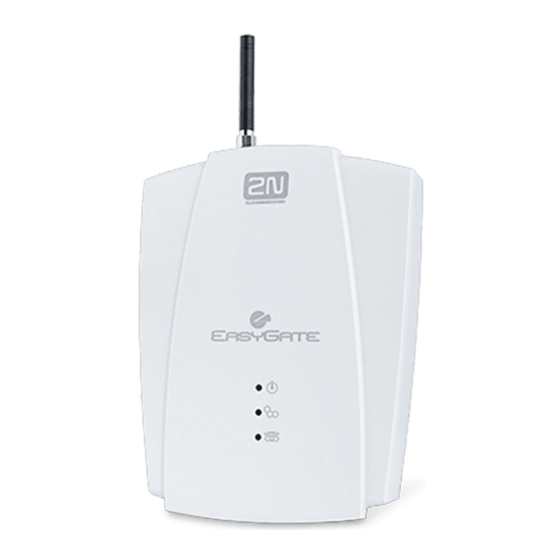
2N® SmartGate consites of GSM gateway in white plastic cover, removable antenna and cables for connecting to phone set and PC ® SmartGate‟s status is indicated by LED diodes on its front side. All possible states are described in the following figure. Figure 2.1 Power supply ®... -
Page 15: Telephone Line Tones - Operational Tones
Ringback tone. Busy tone , programmable cadency In case of call routing to GSM network 2N® SmartGate generate busy tone in any of the following cases: The SIM card has not been installed. 2N® SmartGate is not registered to GSM network. -
Page 16: Telephone Line Tones - Programming Mode
Description Dialing end signaling Only Dialing reception has been terminated. Connection is being established. PIN tone Enter the PIN code. This tone is transmitted upon power up if the PIN has to be entered manually. PUK tone ... -
Page 17: Before You Start
This position is the best for signal reception because a vertical antenna is used. 2N® SmartGate can be operated in the horizontal position too where the GSM signal is good. Install 2N® SmartGate with respect to the GSM signal strength – check the signal strength using the PCManager. - Page 18 It is impossible to operate 2N® SmartGate on sites exposed to direct solar radiation or near heat sources. 2N® SmartGate is designed for indoor use. It may not be exposed to rain, flowing water, condensed moisture, fog, etc.
-
Page 19: Mounting
The Antenna shall be located within the same building as the main equipment. For antenna and cable parameters see the “Technical Parameters”. SIM Card Installation Open the SIM card holder on SmartGate‟s backside, insert the SIM card and close it properly. Figure 2.3 SIM Card Installation Cautions Make sure that the GSM provider‟s SIM card is compatible with the GSM... -
Page 20: Wall Mounting
Mounting Wall mounting 2N® SmartGate is equipped with two hangings on the back side for wall mounting. For drilling holes to the wall could be used drill pattern in QuickStart. Figure 2.4 Zavěšení ® SmartGate na zeď Power Supply Connection 2N®... -
Page 21: Telephone Line Connection
FXS interface on SmartGate. Optionally you can connect analogue fax (special model of SmartGate). If FXO interface of 2N® SmartGate is connected directly to PSTN, you can connect only equipment that is in compliance with the essential requirements and other relevant provisions of Directive 1999/5/EC to FXS port. -
Page 22: Sms Sending Input Connection
SMS Sending Input Connection 2.5 SMS Sending Input Connection You have got a special connector for easy connection to SmartGate. The connector is equipped with screwing clamps to connect wires from a switching contact (device to be monitored). The other connector end can be connected to the respective 2N®... -
Page 23: Configuration 2N® Smartgate
Configuration 2N® SmartGate ® This section describes configuration of the product 2N SmartGate. Here is what you can find in this section: PC Connection to 2N® SmartGate 2N® SmartGate Parameter Programming Table of Parameters ... -
Page 24: Pc Connection
2N® SmartGate Parameter Programming Most of SmartGate‟s parameters have such default values that meet most users‟ demands and need not be changed. Usually you have to program routing tables according to 2N® SmartGate usage. There are two possibilities how to program SmartGate: Use phone line and DTMF programming from connected phone set. -
Page 25: Pc Based Programming
(all LEDs are on). If instructed so by the PCManager during this timeout, 2N® SmartGate remains in this mode as long as it is necessary. If 2N® SmartGate is not reset after the PCManager is terminated, switch the system off and on again. - Page 26 2N® SmartGate parameters configuration the table for setting parameters will open. If you point at a parameter with the mouse, the help text is displayed. 7. When the setting is finished, save data into the gateway. If the gateway is not in its special programming mode, you are invited to set this mode again according point 5.
-
Page 27: Further Data Handling Options
They are not saved in a PC file for security reasons. If you load a PC file into the PCManager and then into SmartGate, the PIN and service password should not change unless you change them manually before saving. -
Page 28: Monitoring
The SIM card IMSI ID and selected SMS service centre necessary for SMS sending; The GSM provider's name and signal strength received by 2N® SmartGate - this information helps you find the optimum signal location (the information is updated in 10s intervals);... -
Page 29: Firmware Upgrade
1. Run the PCManager, select the language for displaying texts on the right-hand side. 2. Click on the upgrade – if 2N® SmartGate is not in its special programming mode, you are invited to switch 2N® SmartGate off and on again. -
Page 30: Table Of Parameters
Dialing parameters Type of dialing Function No.: Select the dialing type to be received by 2N® SmartGate on the FXS interface. 2N® SmartGate accepts only the selected type of dialing, ignoring the others. Setting options: DTMF (0) -2N® SmartGate receives tone dialing only. - Page 31 When DTMF is transmitted in voice channel of GSM network problem with quality can occur, because the GSM compression can damage the signal. You can set digital transmission mode, than SmartGate mutes original DTMF signal from telephone line, and instead of this transmits digital DTMF in signaling channel.
-
Page 32: Tone Settings
Dial tone - cadence Function No.: Dial tone cadence setting. Setting options: Continuous ( 0) -2N® SmartGate generate continuous dial tone Morse A (1) -2N® SmartGate generate dial tone with 330/330/660/660 ms timing Default setting: Continuous Busy tone – frequency 1[Hz] Function No.: Setting of frequency 1 of busy tone. - Page 33 2000/4000 ms (4) -cadence 2 s tone, 4 s pause Default setting: Tone after disconnection Function No.: If the remote subscriber hangs up first, the 2N® SmartGate subscriber can hear the tone selected here. Setting options: Busy (0)-2N® SmartGate transmits the busy tone upon call end.
- Page 34 Ringing signal settings Ringing signal – frequency [Hz] Function No.: Ringing signal frequency setting. Setting options: 25 / 50 Hz-2N® SmartGate rings with 50 or 25 Hz on FXS interface Default setting: 50 Hz Ringing signal - cadence Function No.: Ringing signal cadency setting.
-
Page 35: Telephone Interface Fxo Parameters
Setting step: Default setting: Telephone interface FXO parameters Dialing parameters Number of rings before Off-Hook Function No.: 200 If 2N® SmartGate is programmed as FXO gateway, parameter sets the count of rings before Off-Hook. Setting options: 1-255 Step: Default setting: Time for dialing start Function No.: 202... - Page 36 Timeout for dialing end recognize [s] Function No.: 201 If 2N® SmartGate is programmed as FXO gateway, parameter defines timeout during which 2N® SmartGate waits for further digits to be dialed. It starts to establish connection when this timeout passes. Setting options:...
- Page 37 Table of Parameters Beep after dialing end Function No.: 203 If 2N® SmartGate is programmed as FXO gateway, parameter enables a beep to signal the end of dialing (beginning of outgoing call establishing). Setting options: YES(1)/NO(0) Default setting: Signaling Busy tone detection Function No.: 210...
- Page 38 Function No.: Dial tone cadence setting. Setting options: Continuous ( 0) -2N® SmartGate generate continuous dial tone Morse A (1) -2N® SmartGate generate dial tone with 330/330/660/660 ms timing Default setting: Continuous Ring back tone – frequency 1 [Hz] Function No.: Setting of frequency 1 of ringback tone.
-
Page 39: Fxs Routing Table Parameters
Mobility extension FLASH Mobility Extension FLASH DTMF code Function No.: 240 Fill in DTMF code to enable GSM FLASH function. If 2N® SmartGate receive DTMF dialing corresponding to filled code during GSM - FXO call, it generates FLASH to FXO interface. - Page 40 Every table line includes a phone number prefix (of variable length) and other parameters. The parameters define SmartGate's behavior in case the beginning of the dialed number matches this prefix on the same table row. The table contains 120 rows for up to 120 different prefixes.
- Page 41 Table of Parameters Remember to complete the "Other prefixes" line for a number whose prefix is not found in the table. An example in the figure shows how to bar all international calls with the exception of calls to Slovakia. Calls to Slovakia are routed through FXO interface and the call is established immediately after 14 digits are dialed.
- Page 42 Table of Parameters End with # Function No.: 394 This parameter enables to establish the call when a # is received. The # character is removed from the dialed number. If a # should be part of the dialed number, this function cannot be used for the given prefix. Setting options: YES(1)/NO(0) Default setting:...
-
Page 43: Fxo Routing Table Parameters
Each table pertains to one interface: FXS, FXO and GSM. Calls from FXO interface are routed according to “FXO calls rote to” parameter. You can set 2N® SmartGate as DialThru gateway or as gateway for extension line of PBX. You can program ME function for the DialThru gateway. - Page 44 Mobility Extension - number of rings Function No.: 402 If you program 2N® SmartGate as DialThru gateway and ME number is filled in, 2N® SmartGate starts to establish GSM call to ME number after defined number of rings. Then you can receive incoming FXO call on telephone line or in GSM network.
- Page 45 Table of Parameters Setting options: 0-16 characters (0-9,*,#) Default setting: blank Call enable Function No.: 491 This parameter allows/bars calls with corresponding prefixes. Setting options: YES(1)/NO(0) Default setting: Number length Function No.: 493 The parameter defines the expected length of dialed number. It enables to start dialing into GSM or FXO interface immediately after the last digit is dialed.
-
Page 46: Gsm Routing Table
All parameters related to the dialed number and call routing are arranged in three routing tables. Each table pertains to one interface: FXS, FXO and GSM. Incoming calls from GSM contain the CLI. According to received CLI 2N® SmartGate can do following: ... - Page 47 - It means inclusive of + and international prefix if they are included. If parameter "Substring" > 0, 2N® SmartGate searches filled prefix as substring of the received CLI, but max. to position given by "Substring" parameter. Positions are counted from zero. See examples in "Substring"...
-
Page 48: Sms Sending Input Parameters
Table of Parameters +420 any setting 603198222 4, or more 4, or more Setting options: 0-15 Step: Default setting: Route to Function No.: 591 It is possible to route incoming GSM call to FXS or FXO interface, or reject it. When the call is routed to FXS port you can use the CallBack feature. -
Page 49: Gsm & Sim Parameters
Default setting: According to provider Roaming enable/disable Function No.: You can make 2N® SmartGate work even if it is registered to a foreign GSM network. Setting options: -Disable (0) -The GSM module logs out of a foreign network and attempts to register again in within 5 minutes. - Page 50 Table of Parameters Call Handover workaround Function No.: This parameter offers a workaround to prevent problems during call handover into 1900 1800 MHz) band, caused non-conforming configurations of the 1900 MHz (or 1800 MHz) GSM network. Setting options: -Disable (0) - Disable workaround. -Enable (1) - Enable workaround.
- Page 51 Credit value position in received SMS Function No.: If there are more numbers except credit value in text answer (e.g. date, time and so on) 2N® SmartGate seeks the number corresponding with credit value from given position in text. The seek algorithm skips every non-number character.
-
Page 52: Service Parameters
2N® SmartGate use the Upgrade function. Keep communicating with the manufacturer. Serial number Function No.: - 2N® SmartGate serial number - for information only (cannot be changed). Must be used for communication with the manufacturer. Blocked by operator Function No.: - Refer to GSM &... -
Page 53: Initialization
Initialization of all parameters for SMS sending upon SMS input activation. Global initialization Function No.: 999 Initialization of all 2N® SmartGate parameters including the PIN and service password. Only Global initialization can be done by phone line programming. As parameter of this function service password followed by must be used. -
Page 54: Security Parameters
PIN – value Function No.: 700 Fill in the PIN value for automatic PIN entering upon 2N® SmartGate power up. It is applied only if the SIM card is PIN secured. If the given PIN fails to match the SIM, it is deleted automatically. If entered via a telephone line upon 2N®... -
Page 55: Function And Use
Function and This section describes the basic and extending functions of the product 2N® SmartGate . Here is what you can find in this section: Voice function FAX and Data function SMS Sending Input COM – Serial Interface ... -
Page 56: Voice Function
5 s (programmable parameter). The number is evaluated as complete after this timeout. 3. A short delay follows the last-dialed digit for 2N® SmartGate to await further dialing. Then, the dialing end is signaled and connection is established. -
Page 57: Tariff Pulses 16 Or 12 Khz
Automatic Call ("BabyCall") If the BabyCall function is enabled on FXS interface, a pre-programmed timeout is counted down after off-hook. If you don‟t start dialing within this timeout, 2N® SmartGate signals dialing end and starts to establish a call to the pre-programmed number using GSM network automatically –... -
Page 58: Gateway For Extension Line Of Pbx
FXO interface – extension line of PBX according to the routing table. 2. 2N® SmartGate hooks off the line. If there is filled in the “Dial in” parameter for given CLI, 2N® SmartGate dials it using DTMF. -
Page 59: Gateway For Trunk Line Of Pbx
5 s (programmable parameter). The number is evaluated as complete after this timeout. 3. A short delay follows the last-dialed digit for 2N® SmartGate to await further dialing. Then, the dialing end is signaled and connection is established. -
Page 60: Call Forwarding
Voice function 3. Wait for information tone. You may wait about 3 seconds. 4. Hook on. Information tones: Confirmation - OK: Confirms that the service was configured correctly. Confirmation - bad: Service was not correctly configured Service isn‟t activated by your provider ... - Page 61 Voice function Status check: Call forwarding if busy If activated, incoming calls will be forwarded to the configured telephone number if there is call in progress on SmartGate. Activation for all call types: <Telephone number> Activation for selected call type: <Telephone number>...
-
Page 62: Call Waiting
If the call waiting is activated the incoming call isn‟t refuse if there is call in progress on SmartGate. If there is the other incoming call during connected call it will be indicated by tone. See 0. for multiple calls management. - Page 63 To place the active call on hold to have possibility to dial other outgoing call dial: To place all held calls to active calls and set up conference call dial: To connect the two calls (active and held) and disconnect the 2N® SmartGate from both calls dial:...
-
Page 64: Fax And Data Function
GSM GSM fax and Data connection 2N® SmartGate with fax converter has ability to send and receive GSM fax messages using analogue fax Group 3 connected to telephone line FXS. The fax communication service must be registered with your GSM operator. It is possible to establish data connection using analog modem connected to FXS line. -
Page 65: Supported Fax And Data Protocols
FAX and Data function analogue channel of GSM network and the connection is not successful. In this case it is possible to set the gateway using DTMF commands using device connected to FXS line. This commands can be used for data and fax routing to FXS line or serial line. - Page 66 FAX and Data function connection, to avoid data errors. The data rate for GPRS connection is limited by actual speed of GPRS transfer in GSM network too. This speed is often affected by network load.
-
Page 67: Sms Sending Input
Caution Do not use in life-supporting or property-protection applications because of the character of SMS service and 2N® SmartGate equipment. The manufacturer shall not be liable for health and property damage incurred as a result of SMS sending failure. -
Page 68: Com - Serial Interface
The program is designed for 2N® SmartGate parameters programming. It can read configuration data from the memory and store them in SmartGate. Moreover, all parameters can be saved in your PC file for backup or saving into another 2N® SmartGate system. -
Page 69: Csd Pc-Pc Data Transmission
6 - Fax and Data function. CSD or High-Speed GPRS Data Connection to Internet To connect to the Internet, install the faxmodem driver from the 2N® SmartGate CD-ROM first. Another possibility is to use the GSM provider‟s installation wizard in case it supports the SIEMENS GSM module installed in 2N®... -
Page 70: Sms Sending And Receiving
Outgoing and incoming calls even to GSM can be made during GPRS connection. The GPRS connection remains active during the whole call to GSM but no data can be transmitted (2N® SmartGate is a GPRS terminal of class B). Once the call is terminated, data transmission is recovered immediately. -
Page 71: Sim Card Pin Protection
SIM Card PIN protection 4.5 SIM Card PIN protection If a SIM card is PIN-protected and the PIN is not programmed in SmartGate, GSM LED indicates the state and the PIN tone is transmitted on telephone line. PIN Entering by PCManager Like other parameters, the PIN code can be entered using a PC programming tool. -
Page 72: Automatic Pin Entering
SIM Card PIN protection Automatic PIN Entering You need not enter the PIN upon power up if it is stored in 2N® SmartGate – it is entered automatically. This function is useful in case of power failure; 2N® SmartGate is operable in a short time after power recovery without any intervention by the operating staff. -
Page 73: Free Minutes Option
Free minutes option 4.6 Free minutes option Basic description With Firmware 1.5x and 3.5x only! Free minutes option allows user to control amount of minutes used for four groups of operators in one month period. The user than knows, if performed calls are included in free minutes bundle, or if he has to pay extra price for it. -
Page 74: Commands - Direct Access
Free minutes option Free minutes Function No.: 32x The number of minutes that will be used to refill banks. The selection x is 1 to 4, according to bank number. Setting options: 0-65535 Default setting: Initial time Function No.: 33x Initial time interval in seconds, which is charged for every call, although the call is shorter. -
Page 75: Setting Of Free Minutes Option - Pcmanager
Free minutes option day in month hour minute When the date is valid, the confirmation - OK is generated otherwise there is there confirmation – bad. Refill now The command is intended for refilling of free minutes banks with predefined values (free minutes) manually just now. -
Page 76: Using Free Minutes Option - Step By Step
Free minutes option Using Free minutes option – step by step 1. If your gateway is preset by supplier to be used with some billing scheme, you can continue with step 6 2. Collect all information about billing scheme you use from your operator. You have to set parameters by PCManager. -
Page 77: Technical Parameters
Technical parameters ® This section describes the technical parameters of the product 2N SmartGate. -
Page 78: Technical Parameters
Technical Parameters 5.1 Technical Parameters GSM module, GSM bandwidth MC55i: EGSM 900/850MHz, GSM 1800/1900MHz EGSM 850/900 MHz, Transmission power GSM 1800/1900 MHz Receiver sensitivity -104 dBm HR+FR+EFR Half rate+Full rate+Enhanced full rate Audio Echo cancellation, Echo suppression GPRS Class 10, 4+2 max. 85.6 kbps downlink DATA CSD max. -
Page 79: Telephone Interface Fxo (For Pbx Extension Line)
Technical Parameters Telephone connector type RJ 12, 6/2 Line impedance 600 Loop voltage on hook 48 V DC Loop current max. 40 mA Loop resistance max. 800 Tone frequency adjustable, default 425 Hz Dialing type tone (DTMF) or pulse Ringing voltage 42 Vrms 50/25 Hz Calling line identification... -
Page 80: Data Interface
Technical Parameters max. 1 k Closed loop resistance Open loop resistance Min. 25 k Input overvoltage protection max. +/- 12 V Data Interface Interface type RS-232C Connector D-Sub 9 pins Interface transmission rate 1200 - 115200 bps (autobauding) 8N1 Others Dimensions (w/o connectors) 170 x 130 x 45 mm Operating temperature... -
Page 81: Supplementary Information
Supplementary Information This section describes supplementary information of the product. Here is what you can find in this section: Regulations and directives Troubleshooting List of Abbreviations General Instructions and Cautions. ... -
Page 82: Regulations And Directives
Regulations and directives 6.1 Regulations and directives 2N® SmartGate conforms to the following directives and regulations: Directive 1999/5/EC of the European Parliament and of the Council, of 9 March 1999 – on radio equipment and telecommunications terminal equipment and... -
Page 83: Troubleshooting
2N® SmartGate is in the special PCManager-based programming mode - exit the PCManager to reset SmartGate Try to switch 2N® SmartGate off and on, the LEDs should go off in 3s and signal the status of SmartGate ... - Page 84 Check the COM number setting on PC. Check the COM parameters (1200-115200 bps, 8N1). 2N® SmartGate is not registered to GSM network. A dialing or outgoing call establishing process takes place on SmartGate. An incoming call is ringing on SmartGate.
-
Page 85: List Of Abbreviations
A PC serial port standard. SIM (Subscriber Identity Module) A chip-equipped module to be inserted in a GSM device for identification. ® SmartGate SMS (Short Message Service) A term for the system and one unit (message). - Page 86 List of Abbreviations Software. TTL (Transistor-Transistor Logic) A standard digital technology defining voltage for levels 0 and 1. PSTN Public Switched Telephone Network.
-
Page 87: General Instructions And Cautions
General Instructions and Cautions 6.4 General Instructions and Cautions Please read this User Manual carefully before using the product. Follow all instructions and recommendations included herein. Any use of the product that is in contradiction with the instructions provided herein may result in malfunction, damage or destruction of the product. -
Page 88: Electric Waste And Used Battery Pack Handling
General Instructions and Cautions Electric Waste and Used Battery Pack Handling Do not place used electric devices and battery packs into municipal waste containers. An undue disposal thereof might impair the environment! Deliver your expired electric appliances and battery packs removed therefrom to dedicated dumpsites or containers or give them back to the dealer or manufacturer for environmental-friendly disposal. - Page 89 2N TELEKOMUNIKACE a.s. Modřanská 621, 143 01 Prague 4, Czech Republic Tel.: +420 261 301 500, Fax: +420 261 301 599 E-mail: sales@2n.cz Web: www.2n.cz 1575v1.1.0...
Need help?
Do you have a question about the SmartGate and is the answer not in the manual?
Questions and answers