2N VoiceBlue Next User Manual
Voip network with gsm networks
Hide thumbs
Also See for VoiceBlue Next:
- User manual (112 pages) ,
- Installation manual (9 pages) ,
- Quick manual (3 pages)
Table of Contents
Advertisement
Advertisement
Table of Contents

Related Manuals for 2N VoiceBlue Next


Summary of Contents for 2N VoiceBlue Next
- Page 1 ® VoiceBlue Next User Manual Firmware 1.24 Version 3.11 www.2n.cz ...
- Page 2 The 2N TELEKOMUNIKACE a.s. is the holder of the ISO 9001:2009 certificate. All development, production and distribution processes of the company are managed by this standard and guarantee a high quality, technical level and professional aspect of all our products.
-
Page 3: Table Of Contents
2.4 IP Voice Transmission . . . . . . . . . . . . . . . . . . . . . . . . . . . . . . . . . . . . . . . . . . . . 23 2.5 VoiceBlue Next Connection to VoIP . . . . . . . . . . . . . . . . . . . . . . . . . . . . . . . . . . 26 3. VoiceBlue Next Configuration ......28 3.1 Factory Reset . . . . . . . . . . . . . . . . . . . . . . . . . . . . . . . . . . . . . . . . . . . . . . . . . . . 29 3.2 Basic Configuration – Step by Step . . . . . . . . . . . . . . . . . . . . . . . . . . . . . . . . . . 30 ... -
Page 4: Product Overview
1. Product Overview ® In this section, we introduce the VoiceBlue Next product, outline its application options and highlight the advantages following from its use. This section also includes safety instructions. Here is what you can find in this section: 1.1 Product Description... -
Page 5: Product Description
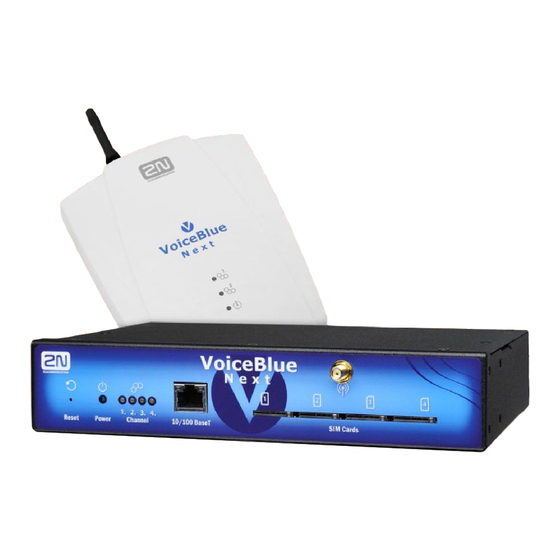
VoiceBlue Next is equipped with all voice mode functions and ® provides the highest user comfort. In addition to voice transmission, 2N VoiceBlue Next enables you to send and receive text messages (SMS). No additional equipment (such as an external phone) is needed for normal operation. You can use the web interface or AT commands for all the gateway settings. -
Page 6: Safety Precautions
If necessary, the GSM gateways may be installed at a safe distance from the prohibited area and connected with the original place through an Ethernet cable. Although GSM gateways are not intended for cars or aeroplanes, all relevant prohibitions and regulations regarding mobile phones apply to them too. ® TELEKOMUNIKACE a.s., www.2n.cz... -
Page 7: Upgrade
The User Manual relates to the 2N VoiceBlue Next firmware version 1.22.0. Text correction. The User Manual relates to the 2N ® VoiceBlue Next firmware version 3.10 1.23.0. The User Manual relates to the 2N® VoiceBlue Next firmware version 3.11 1.24.0. ® TELEKOMUNIKACE a.s., www.2n.cz... -
Page 8: Terms And Symbols Used
Useful information for quick and efficient functionality. Note Routines or advice for efficient use of the device. Future Functions, Innovations grey-marked text in this document designates the functions that are under preparation or development at present. ® TELEKOMUNIKACE a.s., www.2n.cz... -
Page 9: Description And Installation
VoiceBlue Next product installation and connection. Here is what you can find in this section: 2.1 Before You Start 2.2 Factory Settings 2.3 Brief Installation Guide 2.4 IP Voice Transmission 2.5 VoiceBlue Next Connection to VoIP ® TELEKOMUNIKACE a.s., www.2n.cz... -
Page 10: Before You Start
Make sure that you are equipped with all system components necessary ® for putting VoiceBlue Next in operation (SIM card, VoIP phone and/or duly configured SIP line of your SIP Proxy, an available 100BaseT socket and a PC for initial settings). - Page 11 Connector Lay-Out (4-Channel Version) ® The following connectors are mounted on the VoiceBlue Next bottom: 10/100BaseT Ethernet connector with PoE support RESET button – press for a short time to restart the GSM gateway and for a long time to restart the GSM gateway and download the factory settings.
- Page 12 SIM Card Placement (2-Channel Version) ® Lift off the SIM card holder on the VoiceBlue Next backside, insert the SIM card and replace the holder, securing the latch. SIM Card Placement (4-Channel Version) ® Insert a SIM card into one of the four SIM holders on the...
- Page 13 SMS centre and similar provider and SIM card services in your mobile ® phone before inserting the SIM card VoiceBlue Next If two SIM cards are used, both of them must have an identical PIN PIN request disable must be selected.
- Page 14 Potential GSM/UMTS Troubles All 2N GSM gateways work reliably under a long-time full load. The following problems may be caused by GSM/UMTS networks: GSM/UMTS module(s) cannot log in, log in slowly, or log out occasionally. This problem may be caused by any of the following situations: The GSM/UMTS signal is low.
-
Page 15: Factory Settings
The table below includes the factory settings for the key configuration parameters of the GSM gateway: IP address: 192.168.1.2 IP mask: 255.255.255.0 IP gateway: 192.168.1.1 Username: Admin Password: 2n Caution Remember to change the username and password during the first gateway configuration to avoid unauthorised access! ® TELEKOMUNIKACE a.s., www.2n.cz... -
Page 16: Brief Installation Guide
® Any excess of the allowed working temperature may not affect the 2N VoiceBlue Next function immediately but may result in faster ageing and lower reliability. - Page 17 UPS back-up and due overvoltage protection. Wall Mounting (2-Channel Version) ® Follow the instructions below to wall mount VoiceBlue Next Drill two screws into the wall in a relative distance matching the wall mounting ® holes in the VoiceBlue Next rear.
- Page 18 Horizontal Mounting (4-Chanel Version) ® VoiceBlue Next is ready for mounting on a horizontal support. You can stick rubber feet (included in the delivery) on the device if necessary. Follow the instructions below: Put the GSM gateway carefully on a stable horizontal support with its bottom side Stick the rubber feet into the corners as shown below.
- Page 19 Insert the connecting plates (BE CAREFUL! The rear and upper connecting plates have different drilled holes – the upper plate holes are larger and without threading) in the upper and rear holes of one GSM gateway first. Then connect the other unit. ® TELEKOMUNIKACE a.s., www.2n.cz...
-
Page 20: Power Supply Connection
Refer to the status indicators. Warning Connecting a defective or inappropriate power supply adapter may lead to ® a temporary or permanent VoiceBlue Next error! ® Never connect VoiceBlue Next using the PoE and a local adapter at ®... -
Page 21: Antenna Connection
Subs. 2.2 Caution ® Resetting factory values results in a change of the 2N VoiceBlue Next Ethernet interface configuration! Using a defective Ethernet cable may lead to a high packet loss rate in the Ethernet network and subsequent instability and poor quality of all GSM/UMTS calls! ®... -
Page 22: Firmware Upgrade
The antenna splitter is a passive component that combines multiple GSM/UMTS ® channels into one antenna. In VoiceBlue Next , it combines two/four antennae into one. The antenna splitter is placed in the installation box. It is a passive element –... -
Page 23: Ip Voice Transmission
The parameters of these blocks are then inserted in frames of the size of 10 bytes. 2-byte frames are generated for noise transmission. ® During call set-up, a codec is selected automatically for voice transmission. 2N VoiceBlue Next supports the codecs included in the table above. The type of codec to ®... - Page 24 ® In the case of separated direct connection of your SIP Proxy and 2N VoiceBlue Next , use the G.711 codec to achieve a high voice quality. SIP Components The following components are involved in the SIP message exchange: UAC (User Agent Client) – the terminal device client, which initiates SIP signalling.
- Page 25 ® TELEKOMUNIKACE a.s., www.2n.cz...
-
Page 26: Voiceblue Next Connection To Voip
PTP configuration is often used for testing purposes before implementation into the VoIP network. Refer to the figure below for the PTP scheme. ® If you set the incoming SIP Proxy IP address to '0.0.0.0' in the 2N VoiceBlue Next configuration, the GSM gateway will receive calls from any VoIP device. - Page 27 PBX extended with VoIP services), which is responsible for all VoIP signalling. ® Multiple source devices (VoIP phones, e.g.) and multiple target devices (2N VoiceBlue Next , e.g.) can be used in this mode. An internal routing algorithm (Least Cost Router, LCR) of your SIP Proxy is used for routing outgoing GSM and other calls in ®...
-
Page 28: Voiceblue Next Configuration
3. VoiceBlue Next Configuration ® This section describes the VoiceBlue Next configuration. Here is what you can find in this section: 3.1 Factory Reset 3.2 Basic Configuration – Step by Step 3.3 Call Routing 3.4 Web Configuration Interface Gateway Control... -
Page 29: Factory Reset
Ethernet settings and subsequent necessity to reconfigure the gateway. Note To reset the factory values, press the Reset button until the LED indicators start flashing red. Note Push the RESET button for a short time (0.5 s) to restart the GSM gateway. ® TELEKOMUNIKACE a.s., www.2n.cz... -
Page 30: Basic Configuration - Step By Step
3.2 Basic Configuration – Step by Step ® This section will help put your VoiceBlue Next gateway in operation for the first time. Refer to all S. 3 subsections for detailed settings. Install the GSM gateway as instructed in Subs. 2.3. -
Page 31: Call Routing
2N Mobility Extension ® Mobility Extension (ME) is a function that turns your mobile phone into an SIP ® phone taking advantage of all the PBX functions. To make your 2N Mobility ® Extension work efficiently, use the 2N VoiceBlue Next... - Page 32 Fig. 2 shows sending of information texts if an incoming call is not answered. ® Subscriber A calls subscriber B, for whom the Mobility Extension has been permitted with activated “Follow me” and “SMS at no answer” services. Subscriber B ® TELEKOMUNIKACE a.s., www.2n.cz...
- Page 33 Proxy to a mobile telephone. The description of this function is shown in Fig. 3. Figure 3: Call Forwarding Function ® In Fig. 3 subscriber A is talking to subscriber B, for whom the 2N Mobility Extension has been permitted. Subscriber A would like to be forwarded to subscriber C.
- Page 34 GSM network ID is an optional parameter, which is assigned to each LCR record to make the LCR search more convenient. If this parameter is not completed, the list number is only used for identification (1–8). ® TELEKOMUNIKACE a.s., www.2n.cz...
- Page 35 The GSM/UMTS outgoing call routing algorithm is launched whenever the SIP Proxy ® ® routes an outgoing call to VoiceBlue Next . Outgoing calls are routed via VoiceBlue Next as follows: The calling subscriber dials the subscriber number and the SIP Proxy routes it to ®...
- Page 36 If the incoming call is still not processed, the gateway will receive the call and ® send either a voice message or the dialtone to the caller. After that, 2N VoiceBlue Next awaits the required count of digits necessary for connection set-up.
- Page 37 Having received the count of digits included in the GSM incoming groups / Minimum count of DTMF digits table, the gateway will set up connection to the SIP Proxy. Use the GSM gateway web interface to upload the DISA welcome note. ® TELEKOMUNIKACE a.s., www.2n.cz...
-
Page 38: Web Configuration Interface
3.4 Web Configuration Interface Essential Data ® VoiceBlue Next web interface supports the following web browsers: MS Internet Explorer v9 Mozilla Firefox v4 and higher Any other web browsers may cause troubles. The recommended screen resolution is 1280x1024 and colour quality 32bit or higher. The configuration interface is available in the English language version only at present. - Page 39 The home page also includes the Logout button. You wil be notified of successful logout after every logout action to avoid re-use of your login data. There are four more sections in the right-hand upper menu: ® TELEKOMUNIKACE a.s., www.2n.cz...
- Page 40 Management – for firmware update, license upload and configuration upload/download. The main window displays information on the gateway licence status, firmware and ® bootware versions and the VoiceBlue Next Ethernet interface MAC address. In addition, you can download a new licence here. ® TELEKOMUNIKACE a.s., www.2n.cz...
- Page 41 Auto licence is added via the SIMStar server ® If the current Licence status blocked during automatic licensing, VoiceBlue Next will be restarted during licence adding. If the current Licence status unblocked during automatic licensing, ® Gateway limitation will be prolonged without VoiceBlue Next restart.
-
Page 42: Voice Messages
Voice message detector Message 35 Voice message detector Message 36 Voice message detector Message 37 Voice message detector You can choose which message will be uploaded or use detection by file name. Detection requires file name: "mess[index message][optional ® TELEKOMUNIKACE a.s., www.2n.cz... -
Page 43: Log File
The maximum capacity is 100,000 call records. When this limit is reached, the oldest record(s) will be deleted automatically! The latest 1,000 call records are displayed in the web interface. Downloading of a high amount of CDR may take up to several tens of seconds. ® TELEKOMUNIKACE a.s., www.2n.cz... - Page 44 AutoCLIP routing table The window displays the current state of the AutoCLIP table. The bottom part of the window includes icons for saving the LOG file into a file and refreshing the listing in the web window. ® TELEKOMUNIKACE a.s., www.2n.cz...
-
Page 45: Sip Registration
Note The maximum AutoCLIP routing table capacity is 256 records. SIP registration The window displays the current SIP registration state of the gateway. Online report The window displays on-line gateway tracing. ® TELEKOMUNIKACE a.s., www.2n.cz... -
Page 46: Gateway Configuration
Saving call data (CDR) – select the call types on which records are to be saved into the CDR file. ® Gateway ID – identifies VoiceBlue Next numerically in the CDR in case multiple devices generate the CDR in the network. Summer/winter time Automatically switch to summer/winter time –... -
Page 47: Voip Parameters
Send 200 OK instead of 180/183. Send 200 OK and BYE when rejected from GSM. ® Send 200 OK on REGISTER request – virtual registration of the device in 2N VoiceBlue Next (necessary for registration-requiring equipment). Replace CLIP from GSM with Caller ID. - Page 48 VoiceBlue Next will receive requests from any IP address. ® SIP Proxy (GSM / IP) – IP address of the SIP Proxy to which 2N VoiceBlue Next turns in the case of a GSM incoming call. SIP registrar – IP address of the SIP registration server.
- Page 49 ® Refer to Subs. 4.2 for easy tracing through VoiceBlue Next Tones generated to VoIP Ring tone to VoIP – generate a ringing tone of your own, or transmit a real ringing tone from the GSM/UMTS networks. GSM basic parameters...
- Page 50 End call with SHUP – end calls with the SHUP command. Enable HR codec – enable the Half Rate codec for the GSM network. Enable AMR codec – enable the Adaptive Multi-Rate codec for the GSM network. ® TELEKOMUNIKACE a.s., www.2n.cz...
- Page 51 Tone generated for incoming calls from GSM/UMTS Dialtone – the dialtone type for GSM/UMTS incoming calls. Ring tone – the ringing tone type for GSM/UMTS incoming calls. Generate busy tone to GSM/UMTS – generation of the busy tone for call end. ® TELEKOMUNIKACE a.s., www.2n.cz...
- Page 52 Cause translation Here you can convert the release cause received from GSM/UMTS into another ISDN release cause. The resultant ISN cause number will be transformed into a VoIP SIP code as included in the table below: ® TELEKOMUNIKACE a.s., www.2n.cz...
- Page 53 Causes of failed calls ® Define the GSM failed call causes for the SIM Star Server . If you enter no record into the Causes of failed calls table, every non-connected call will be evaluated as a failed call. ® TELEKOMUNIKACE a.s., www.2n.cz...
- Page 54 See the two items below for outgoing and incoming group settings. GSM outgoing groups ® VoiceBlue Next allows you to work with two groups of outgoing calls for each of which you can set variable connection set-up modes and count of used minutes and sent SMS messages for a selected period.
- Page 55 Modify (" removes one digit) – you can change the CLIP. The "– character is used for deleting one char from the left. Caution Send CLIP from VoIP to GSM service must be supported by the GSM/UMTS provider. If not, the provider's network may reject the call! ® TELEKOMUNIKACE a.s., www.2n.cz...
- Page 56 First count – set the length of the first pulse after which the pulse counting will be changed as set in the Next count parameter Next count – set the length of one pulse in seconds after the time as defined in ® TELEKOMUNIKACE a.s., www.2n.cz...
- Page 57 The manufacturer is not liable for any additional call costs in case the GSM/UMTS provider's free minute/SMS limits are exceeded. GSM incoming groups ® VoiceBlue Next allows you to work with two groups of incoming calls for each of which you can set variable connection set-up modes. ®...
- Page 58 00420261301500 00 inserted before CLIP received – 0261301500 First two digits removed from CLIP received First three digits removed from CLIP received, prefix –––99 99261301500 '99' added Looping of voice message – set the voice message playing time. ® TELEKOMUNIKACE a.s., www.2n.cz...
- Page 59 The window helps you adapt the gateway to calling to variable GSM networks. You can set the prefix-based call routing rules here and identify up to sixteen different groups for routing. Prefix list 1–16 Sixteen prefix groups to be assigned in the LCR table. ® TELEKOMUNIKACE a.s., www.2n.cz...
- Page 60 From (channels/groups) – source channels or groups via which calls are ® routed to VoiceBlue Next GSM ALL – any of the GSM incoming groups can be used for call routing. GSM GRP1–4 – define one GSM incoming group or a range of GSM incoming groups via which call routing will be enabled.
- Page 61 Groups – define the outgoing GSM groups or interface via which outgoing calls ® will be routed from VoiceBlue Next . If the defined interface is inactive or the outgoing GSM group tariff is exhausted, the next row will be applied.
- Page 62 Mobility Extension function. Ethernet configuration This window helps you configure the Ethernet interface of your gateway. ® Use DHCP – enable/disable the DHCP client function in VoiceBlue Next ® IP address – the fixed IP address (v4) of the VoiceBlue Next Ethernet interface.
-
Page 63: Web Configuration
DHCP server are displayed in the IP address Subnet mask Default gateway items. Login configuration ® The window helps you set the access password and name for the 2N VoiceBlue Next web interface. Use the same data for Telnet connection too. Caution Remember to change... - Page 64 – any SMS whose text beginning matches this parameter is evaluated as a delivery report. Note If multiple SMS are sent to one and the same number, delivery reports are assigned to them according to the sending time, starting from the oldest one. ® TELEKOMUNIKACE a.s., www.2n.cz...
- Page 65 The count of user accounts is file-licensed. Refer to Management / Licence key for the current GSM gateway licence details. Users This section helps you manage the SMS users. Select a communication protocol for user adding (SMTP/POP3 or SMPP). ® TELEKOMUNIKACE a.s., www.2n.cz...
- Page 66 200. Refer to Management Licence key for the current GSM gateway licence details. The maximum count of SMPP user accounts is 16. With the Email/Web user accounts, the maximum count is 200 as specified in the licence. ® TELEKOMUNIKACE a.s., www.2n.cz...
- Page 67 – set the SMS delivery acknowledging message subject. POP3 – Subject of e-mail (not delivered) – set the SMS non-delivery acknowledging message subject. POP3 – Subject of e-mail (send error) – set the SMS sending failure message subject. ® TELEKOMUNIKACE a.s., www.2n.cz...
- Page 68 SMS. The sender information will be displayed at the beginning of the SMS message. SMTP – Add "Subject" to SMS – add 'Subject' from the Email message to the outgoing SMS. The subject information will be displayed at the beginning of the SMS message. ® TELEKOMUNIKACE a.s., www.2n.cz...
- Page 69 – enter addressee's new telephone number TON – type of number NPI – numbering plan indicator Incoming SMS routing This section helps you set the incoming SMS routing rules, which are included in the incoming SMS routing table. ® TELEKOMUNIKACE a.s., www.2n.cz...
- Page 70 SMS will be stored in the outgoing SMS database until the set limits are restored. Outgoing SMS routing This section helps you define the outgoing SMS routing rules, which are included in the outgoing SMS routing table. ® TELEKOMUNIKACE a.s., www.2n.cz...
- Page 71 If all the set rules are met in a row, the SMS is routed according to the row. Control This section helps you monitor the system. It includes storage filling information and AutoCLIP records. SMS queues The subsection displays the current SMS storage state. ® TELEKOMUNIKACE a.s., www.2n.cz...
- Page 72 (multipart) SMS five times. If none of the SMS sending attempts is successful, the SMS will be deleted from the outgoing SMS database and an Incoming SMS count - Failed message is generated by the gateway. ® TELEKOMUNIKACE a.s., www.2n.cz...
-
Page 73: Send Sms
Phone number – enter the SMS recipient's phone number. Message – enter the SMS text to be sent. Note The maximum message length is 10 SMS. The message can use 7-bit encoding (up to 1520 characters) or 16-bit encoding (up to 670 characters). ® TELEKOMUNIKACE a.s., www.2n.cz... - Page 74 Another VoiceBlue NEXT (ESME) gateway and a PC on which the SMPP (ESME) application is running are connected to these accounts via SMPP. An SMS coming to 2N ® VoiceBlue NEXT via SMPP is routed according to the gateway outgoing routing rules and sent to GSM.
- Page 75 Read the User Manual carefully and check all parameters. Find answers to the frequently asked questions at http://faq.2n.cz Consult your servicing partner. You are recommended to attend a 2N certified training to improve your installation chances. ® TELEKOMUNIKACE a.s., www.2n.cz...
- Page 76 SMTP/POP3 Basic Configuration – Step by Step ® This section helps you define the VoiceBlue NEXT basic parameters for SMS sending/receiving via SMTP/POP3. Read the Messaging subsection carefully before setting details. Figure 1 shows sending/receving SMS via SMTP/POP3. Having created user accounts ®...
- Page 77 Read the User Manual carefully and check all parameters. Find answers to the frequently asked questions at http://faq.2n.cz Consult your servicing partner. You are recommended to attend a 2N certified training to improve your installation chances. ® TELEKOMUNIKACE a.s., www.2n.cz...
-
Page 78: Common Settings
The SNMP trap is sent automatically whenever the defined value is exceeded. SNMP General Enabled – enable/disable the SNMP service. Community – SNMP community is a group that owns the device and control stations on which SNMP is running. Default value = public. ® TELEKOMUNIKACE a.s., www.2n.cz... - Page 79 MIB browser. Caution The SNMP service works properly on condition that: SNMP is licensed in the Management section. The primary IP address, transport port and community parameters are completed. SNMP is enabled in the Monitoring section.e ® TELEKOMUNIKACE a.s., www.2n.cz...
- Page 80 Number of SMS/SMPP messages in memory exceeds defined max level Number of SMS/SMPP messages in memory decreased under defined max level Number of SMS/SMPP messages in memory exceeds defined max level Number of SMS/SMPP messages in memory decreased under defined max level ® TELEKOMUNIKACE a.s., www.2n.cz...
-
Page 81: Test Call
Test Call This section helps you test calls via the gateway interfaces or verify the LCR ® settings. Both incoming and outgoing calls to/from all the VoiceBlue Next interfa ces can be tested. Status Call status Connection channel – display the channel for the selected interface for outgoing test calls. - Page 82 Source channel – select the source channel for the outgoing call interface. Only Destination channel - According to LCR is used. Wait on channel – select the channel for the incoming call interface. Dial – called number. Clip – calling number. ® TELEKOMUNIKACE a.s., www.2n.cz...
-
Page 83: Firmware Update
Any other ® firmware type may damage 2N VoiceBlue Next irreversibly After the new firmware file is stored and sent, the GSM gateway is restarted automatically. Licence key ® This section helps you upload the licence file/code to VoiceBlue NEXT provides information on the current licence file. - Page 84 Configuration download ® The window helps you download the current VoiceBlue Next configuration. The file format is CFG–M202–gateway_serial_number–rrrrmmdd–hhmmss.tar Configuration upload ® The window helps you upload new configuration settings into VoiceBlue Next nfiguration. The Ethernet interface and login data remain the same!
- Page 85 Others SIM Client ® This section is displayed for those GSM gateways only that support the 2N SIM Star system connection – remote SIM card function. This subsection helps you send and receive SMS via the modules. You can also use the SMS user account for SMS sending/receiving. Refer to the Web Configuration subsection for SMS user configuration details.
-
Page 86: Advanced Configuration
4. Advanced Configuration ® This section describes communication with VoiceBlue Next using a terminal. Here is what you can find in this section: 4.1 Terminal-Based Communication 4.2 AT Interface 4.3 LOGs 4.4 CDR 4.5 SDR 4.6 Available Status Messages 4.7 Statistics 4.8 Tracing... -
Page 87: Terminal-Based Communication
It uses an extended set of AT commands for configuration. Refer to Subs.4.2 for the list of terminal AT commands. Example of a login window: [ VoiceBlue Next ] V–01.00.01 B–00.91 Date/time: 15.1.2010/20:56:53.98 SNumber: M202–1501270008 Login: Admin Password: ** Access Data ®... -
Page 88: At Interface
4.2 AT Interface ® VoiceBlue Next uses the list of AT commands derived from the standard AT set for configuration and monitoring purposes. The configuration entering commands start with AT%parameter_id. The configuration writing out commands start with AT§ion. The following list of AT commands is universal and some commands may not be ®... - Page 89 AT&VE – Overview of VOIP parameters AT&N# – Overview of parameters of network list # (#=1–8) AT&NALL – Overview of parameters of all network lists AT&R – Overview of LCR lines Default Reset AT&FRES – Reset with gateway factory settings ® TELEKOMUNIKACE a.s., www.2n.cz...
- Page 90 AT&BSYS=RESET – Reset of PRIGW AT&Gxx=RESET – Reset of GSM module xx AT&Gxx=BLOCK – Block of GSM module xx AT&Gxx=DOWN – Transfer of GSM module into the sleep mode AT&Gxx=ON – Transfer of GSM module into the idle mode ® TELEKOMUNIKACE a.s., www.2n.cz...
- Page 91 AT%N#1=pr/n,…pr/n – List of prefixes dialled into ISDN (to be used for LCR table) pr=prefix n=length of number (parameter /n is optional) AT%N#2..7=pr/n,…pr/n – Other 7 lists of prefixes dialled into ISDN AT%N#9=net,max – Net-network number, max-default length of number dialled from ISDN ® TELEKOMUNIKACE a.s., www.2n.cz...
- Page 92 – status of layer 3 sts2 – status of layer 2 phs2 – substatus of layer 2 type – type of wireless engine AT^MI=ch – Module info ch = 0–31 *minfo: ch,sim,netid,"oper",new,cnt – Response to AT^MI ® TELEKOMUNIKACE a.s., www.2n.cz...
- Page 93 GSM group 1..8. Possible answers: *smserr (busy,write) or *smsout AT^SS=ch,mem – Command for changing SMS storage. Mem (1;2;3) = type of storageSiemens:1=SM, 2=ME, 3=MEEricsson:1=SM, 2=ME, 3=MEWavecom:1=SM, 2=ME, 3=SR Huawei:1=SM, 2=SM, 3=SMSierraWir.:1=SM, 2=ME, 3=SRMotorola:1=IM, 2=IM, 3=IM ® TELEKOMUNIKACE a.s., www.2n.cz...
-
Page 94: Logs
Gateway control – LOG file section or use the AT&L AT command for Telnet sessions. The following list of LOG statuses is ® universal and some LOGs may not be included in VoiceBlue Next Type Text Description [Power on] System switched on... - Page 95 Error of isdn layer 3: timeout in status # on module G3–ERR (g##) tout sts # Error of connecting layer 4: timeout in status # on call C4–ERR (p##/g##) between channel p## and GSM module g## ® TELEKOMUNIKACE a.s., www.2n.cz...
-
Page 96: Cdr
(to be implemented in higher firmware versions) / gateway ID (optional) Column called party number (CDN) Column 11: calling party number (CGN) Column 12: SIM card slot number / SIM card IMSI or SCID ® TELEKOMUNIKACE a.s., www.2n.cz... -
Page 97: Sdr
SANS – SMS after successful call SNOS – SMS at no answer SWEB – SMS was sent via web interface ® SSIM – simulation SMS was sent via 2N SIMStar server ® RSIM – simulation SMS was received 2N SIMStar server... -
Page 98: Available Status Messages
4.6 Available Status Messages The following list of statuses is universal and some messages may not be included in ® VoiceBlue Next GSM Layer Statuses GSM Layer 2 INIT – GSM module initialisation start (follow PINREQ) SIM0 – Module switch to internal SIM card (follow INIT) PINREQ –... - Page 99 FUNCFILE – Content of debug file is being written out LCRFILE – (not used so far) Telnet Layer LOGOUT – User logged-out LOGIN – User is entering name PASSW – User is entering password IDLE – User logged-in ® TELEKOMUNIKACE a.s., www.2n.cz...
- Page 100 G3-ERR – GSM module layer 3 error (gate3) C4-ERR – Link layer error (call4) Record Type in Call File I-FD – Unconnected incoming call attempt I-OK – Connected incoming call O-FD – Unconnected outgoing call attempt O-OK – Connected outgoing call ® TELEKOMUNIKACE a.s., www.2n.cz...
-
Page 101: Statistics
----------------------------------------------------------------------------------------------- #i1 inc ( 2.01) 0:00:00 #i2 inc ( 2.01) 0:00:00 #i3 inc ( 2.01) 0:00:00 #i4 inc ( 2.01) 0:00:00 group (reset) minutes hhhh:mm:ss calls reject failed red.in redout ® TELEKOMUNIKACE a.s., www.2n.cz... - Page 102 0:00:00 #m2 inc ( 2.01) 0:00:00 #m3 inc ( 2.01) 0:00:00 Statistics of outgoing calls on all modules [Statistics of outgoing calls on all modules] network (reset) minutes hhhh:mm:ss calls reject failed c.offs errors ------------------------------------------------------------------------------ ----------------- ® TELEKOMUNIKACE a.s., www.2n.cz...
- Page 103 (reset) minutes hhhh:mm:ss calls reject failed c.offs smses ------------------------------------------------------------------------------ ----------------- #m0 inc (12.03) 0:00:00 #m0 rem (12.03) 0:00:00 module (reset) minutes hhhh:mm:ss calls reject failed c.offs smses ------------------------------------------------------------------------------ ----------------- #m0 out (12.03) 0:00:00 #m0 rem (12.03) 0:00:00 module (reset) minutes hhhh:mm:ss calls limit ® TELEKOMUNIKACE a.s., www.2n.cz...
- Page 104 ------------------------------------------------------------------------------ ----------------- #m0 day (12.03) 0:00:00 #m0 rem (12.03) 0:00:00 module (reset) min0:ss limit min1:ss limit min2:ss limit min3:ss limit ------------------------------------------------------------------------------ ----------------- #m0 fre (12.03) 0:00:00 0:00:00 0:00:00 0:00:00 #m0 rem (12.03) 0:00:00 0:00:00 0:00:00 0:00:00 ® TELEKOMUNIKACE a.s., www.2n.cz...
-
Page 105: Tracing
4.8 Tracing ® VoiceBlue Next allows for operation tracing (VoIP, SIP, GSM). Tracing is accessible in one session only at a time, the other tracing requests are rejected with BUSY. With regard to a rather extensive volume of data, we recommend that the Write communication into file function should be activated before tracing. -
Page 106: External Sms Control
*smspdu: ch,ix,sts,len,pdu,csum – Content of SMS message or status confirmation. *smsdel: ch,ix – An SMS message or status confirmation was deleted from position ix. *smserr: ch[/id],ix,req,err,cms – Response to an error command. *smssel: ch,cnt – Confirmation of an SMS storage change. ® TELEKOMUNIKACE a.s., www.2n.cz... -
Page 107: Technical Parameters
Power input: Up to 20W Interface Protocols: TCP,UDP,IP,RTP,TELNET,http,DHCP Connector: 1x 10/100BaseT Ethernet Administration: AT commands, web interface VoIP Signalling: SIP DTMF: RFC2833 Count of voice channels: 4 Voice codecs: G.711 PCM at 64 kbpsG.729 Annex AB PCM companding: A-law/u-Law (optional) ® TELEKOMUNIKACE a.s., www.2n.cz... - Page 108 Power input: Up to 20W Interface Protocols: TCP,UDP,IP,RTP,TELNET,http,DHCP Connector: 1x 10/100BaseT Ethernet Administration: AT commands, web interface VoIP Signalling: SIP DTMF: RFC2833 Count of voice channels: 4 Voice codecs: G.711 PCM at 64 kbpsG.729 Annex AB PCM companding: A-law/u-Law (optional) ® TELEKOMUNIKACE a.s., www.2n.cz...
- Page 109 GSM: Cinterion MC55i-W, or Wavecom Q55, or Telit (according to the GSM module type used ) UMTS Audio: HR/FR/EFR/AMR USIM/SIM card: Small plug-in 3V Antenna: One external antenna (integrated antenna splitter) SMA FEMALE connector Others Working temperature: 5°C–45°C Air humidity: Max 95% at 40°C ® TELEKOMUNIKACE a.s., www.2n.cz...
-
Page 110: Supplementary Information
6. Supplementary Information ® This section provides supplementary information on VoiceBlue Next Here is what you can find in this section: 6.1 Troubleshooting 6.2 List of Abbreviations 6.3 Regulations and Directives 6.4 General Instructions and Cautions ® TELEKOMUNIKACE a.s., www.2n.cz... -
Page 111: Troubleshooting
6.1 Troubleshooting For the most frequently asked questions refer to faq.2n.cz ® No LED is shining on VoiceBlue Next ® VoiceBlue Next is disconnected from the power supply. ® VoiceBlue Next fails to log in to the GSM network. Check the SIM card. -
Page 112: List Of Abbreviations
SW (Software) TCP (Transmission Control Protocol) UCMD (UDP commands) UDP (User Datagram Protocol) UMTS (Universal Mobile Telecommunication System) UPS (Uninterruptible Power Supply) USSD (Unstructured Supplementary Service Data) VoIP (Voice over Internet Protocol) WAN (Wide Area Network) ® TELEKOMUNIKACE a.s., www.2n.cz... -
Page 113: Industry Canada
6.3 Regulations and Directives Europe ® VoiceBlue Next conforms to the following directives and regulations: Directive 1999/5/EC of the European Parliament and of the Council, of 9 March 1999 – on radio equipment and telecommunications terminal equipment and the mutual... - Page 114 Operation of this equipment in a residential area is likely to cause harmful interference in which case the user will be required to correct the interference at his own expense. Changes or modifications not approved by the responsible party could void the user’s authority to operate the equipment. ® TELEKOMUNIKACE a.s., www.2n.cz...
-
Page 115: General Instructions And Cautions
The manufacturer also assumes no responsibility for additional costs incurred by the consumer as a result of making calls using a line with an increased tariff. ® TELEKOMUNIKACE a.s., www.2n.cz... - Page 116 Make sure that the devices to be disposed of are complete. Do not throw battery packs into fire. Battery packs may not be taken into parts or short-circuited either. ® TELEKOMUNIKACE a.s., www.2n.cz...
- Page 117 2N TELEKOMUNIKACE a.s. Modřanská 621, 143 01 Prague 4, Czech Republic Phone: +420 261 301 500, Fax: +420 261 301 599 E-mail: sales@2n.cz Web: www.2n.cz PR1561v3.11 ® TELEKOMUNIKACE a.s., www.2n.cz...
Need help?
Do you have a question about the VoiceBlue Next and is the answer not in the manual?
Questions and answers