2N StarGate User Manual
Hide thumbs
Also See for StarGate:
- User manual (190 pages) ,
- How to set (5 pages) ,
- Quick manual (4 pages)

Related Manuals for 2N StarGate


Summary of Contents for 2N StarGate
-
Page 1: User Manual
® ® StarGate / 2N StarGate UMTS ® ® BlueStar, 2N BlueTower User Manual Version 3.0.0 www.2n.cz Firmware 2.30.02... - Page 2 1999/5/EC directive. For the full wording of the Declaration of Conformity see the CD-ROM enclosed and at www.2n.cz. The 2N TELEKOMUNIKACE company is a holder of the ISO 9001:2000 certificate. All...
-
Page 3: Table Of Contents
Table of Contents 1. Product Overview............... 7 System ..........................8 ® StarGate ........................8 ® BlueStar ........................10 ® BlueTower ....................... 12 Product Description ..................... 16 Basic Features........................ 16 ® Advantages of 2N StarGate/BlueStar/BlueTower ............16 Innovations ........................18 Terms and Symbols Used ................... 19 Manual Symbols ...................... - Page 4 Quick Step-by-Step Manual ..................65 Quick Step-by-Step Manual for ISDN PRI Card ............. 65 Quick Step-by-Step Manual for VoIP Card ..............66 ® Quick Step-by-Step Manual for 2N SIM Star ..............67 System Upgrade ......................69 Configuration Tool ....................... 70 Program Installation .......................
- Page 5 5. Technical Parameters ............ 161 StarGate Technical Parameters ................163 BlueStar Technical Parameters ................165 BlueTower Technical Parameters ................167 6. Supplementary Information .......... 169 Regulations and Directives ..................170 Troubleshooting ......................171 List of Abbreviations ....................173 General Instructions and Cautions ................175...
-
Page 7: Product Overview
Product Overview ® In this section, we introduce the 2N StarGate / BlueStar / BlueTower product, outline its application options and highlight the advantages following from its use. This section also includes safety instructions. Here is what you can find in this section: System ... -
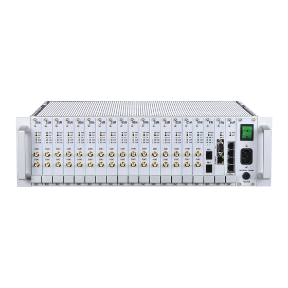
Page 8: System
Basic Dimensions ® ® StarGate is the biggest GSM gateway in the 2N PRI gateways family. The system is integrated in a 19” subrack of the height of 3U and depth of 360mm. The front side is open, equipped with slots for plug-in boards with front panels. The panel includes the main switch. - Page 9 Examples of Used Types ® Empty 2N StarGate Rack 2N® StarGate with 16 GSM Boards, Basic CPU, VoIP Interface and AC Power Supply 2N® StarGate with 16 UMTS Boards, Enhanced CPU, 2 ISDN PRI Interfaces and AC Power Supply Note Please keep all cards in the right positions.
-
Page 10: Bluestar
Basic Dimensions ® ® BlueStar is a GSM gateway from the 2N PRI gateway family with the capacity up to 16 GSM / UMTS channels. The system is integrated in a 19” subrack of the height of 3U and depth of 360mm. The front side is open, equipped with slots for plug-in boards with front panels. - Page 11 GSM or UMTS cards (one for two GSM / UMTS channels) Remaining space (each 4HP) Examples of Used Types 2N® BlueStar 8 GSM Boards, Basic CPU, 2 ISDN PRI Interfaces, Integrated Antenna Splitter and AC Power Supply Note Please keep all cards in the right positions. Wrong positions will cause ...
-
Page 12: Bluetower
Basic Dimensions ® ® BlueTower is the smallest of the 2N PRI gateway family, featuring the capacity up to 8 GSM / UMTS channels. The system is integrated in a small 19” subrack of the height of 3U, width of 29HP and depth of 320mm. The front side is open, equipped with slots for plug-in boards with front panels. - Page 13 Basic or enhanced CPU card AUX card 1ISDN PRI or 2ISDN PRI card GSM or UMTS cards (one for two GSM / UMTS channels) Remaining space (each 4HP) Examples of Used Types 2N® BlueTower with 2 UMTS Boards, Enhanced CPU, VoIP Interfaces and Integrated...
-
Page 14: Power Supply
System Antenna Splitter 2N® BlueTower with 2 UMTS Boards, Basic CPU, 2 ISDN PRI Interfaces and Integrated Antenna Splitter Note Please keep all cards in the right positions. Wrong positions will cause malfunction of whole system! In the case of VoIP card replacement by ISDN PRI (and vice versa) please ... - Page 15 System High voltage may cause a serious injury or death! You are recommended to connect the gateway to the UPS system. ...
-
Page 16: Product Description
Basic Features ® StarGate / BlueStar / BlueTower is a compact yet highly sophisticated system. It supports full remote supervision and configuration via an IP network or using an external modem over a BRI-ISDN and analogue line, or over a B channel in a PRI- ISDN trunk. - Page 17 ® Support of remote SIM card function (2N SIM Star); ® Possibility to replace internal LCR with an external solution (2N ERM); Remote control, configuration and firmware upgrade; High connection rate and ASR, low PDD. ...
-
Page 18: Innovations
If you program your StarGate / BlueStar / BlueTower parameters by means of a computer, you need the PRI config program or a web browser (when using the eCPU web interface ). -
Page 19: Terms And Symbols Used
Useful information for quick and efficient functionality. Note Routines or advice for efficient use of the device. Future Functions A grey-marked text in this document specifies the ® StarGate/BlueStar/BlueTower functions that will be supported in the future. -
Page 21: Description And Installation
Description and Installation ® This section describes the 2N StarGate/BlueStar/BlueTower product and its installation. Here is what you can find in this section: Plug-In Boards Antenna and Antenna Splitters Gateway Rack Configuration Installation ... -
Page 22: Plug-In Boards
Wrong positions may cause malfunction of the whole ® system. The type and quantity of the cards used in your 2N StarGate / BlueStar / BlueTower gateway depend on the part number of the gateway and other components. - Page 23 Plug-In Boards COM1 Serial Interface Parameters The COM1 interface is used as a local port for temporary connection of a PC (terminal) for installation and servicing purposes and permanent connection of the SMS server (supervision PC). It provides local monitoring, configuration, tracing and firmware upgrade.
- Page 24 Plug-In Boards Fig. 2.1 Configuration Jumpers...
-
Page 25: Enhanced Cpu Board
A comfortable graphic web interface for easy gateway remote control and configuration; ® Support of the 2N SIM Star system; Support of the SMTP and POP3 protocols for sending / receiving SMS; CDR downloader (an SD card is required);... - Page 26 Plug-In Boards Ext. unit = Indication LEDs of the extension unit. COM1 Serial Interface Parameters The COM1 interface is used as a local port for temporary connection of a PC (terminal) for installation and servicing purposes and permanent connection of the SMS server (supervision PC).
- Page 27 Plug-In Boards Warning Never use metal tools for battery replacement; neither the new nor the old battery may be short-circuited! A short-circuit may result in battery damage or explosion!!! Dispose of used batteries in accordance with applicable regulations - put them in a recycling yard, for example.
- Page 28 Plug-In Boards Fig. 2.2 Configuration Jumpers...
-
Page 29: Aux Board
Plug-In Boards AUX Board Board Description The AUX board contains a switching array and storage of voice messages controlled by an independent processor system separated from the system bus. The AUX port is used for making test calls or recording voice messages. The input amplifier is designed for an electret microphone, the output amplifier for 150 Ohm earphones. - Page 30 Plug-In Boards Configuration Jumpers Do not change ! JP4a HDLC chip JP4b JP4c Do not change ! JP4d Connected to AUX CPU Connected to Basic CPU There are four configuration jumper blocks on the AUX board. Jumpers JP1 and JP2 are disconnected by default –...
- Page 31 Plug-In Boards JP3 are connected as shown in Fig. JP3a (connected to the main basic CPU) and jumpers JP4 are configured as shown in Fig. JP4a. ISDN PRI Interface Remote Control Chip An HDLC chip is also located on the AUX board, enabling remote control over the ISDN PRI interfaces.
-
Page 32: Pri Board
Plug-In Boards PRI Board Board Description The PRI board contains one or two (depends on the part number) ISDN interfaces and PCM bus timing circuits. PRI 1 is designed as an internal interface (with an activated LCR function) and PRI 2 as an external interface (all calls from the port are always routed to PRI 1). - Page 33 Plug-In Boards Configuration Jumpers JP4: Back-up connection Activated Deactivated JP2: PRI 2 interface type settings NT mode TE mode JP3: PRI 1 interface type settings NT mode TE mode There are three configuration jumper blocks on the PRI board. JP2 and JP3 are used for hardware switching of the ISDN PRI connector into the TE / NT configuration.
- Page 34 Plug-In Boards Warning The back-up connection (JP4) works only in case the wire settings of PRI 1 (JP3) and PRI 2 (JP2) are set in the opposite way (e.g. PRI 1 as NT, PRI 2 as TE). Note Boards with just one PRI interface (1PRI boards) have the same settings ...
- Page 35 Plug-In Boards Example of Connection with 2ISDN PRI Board EuroISDN EuroISDN Q.931 EDSS1 Q.931 EDSS1 PRI port mode = TE PRI 1 port mode = TE PRI 1 port mode = TE PRI 1 port mode = TE Synchronisation = Slave Synchronisation = Slave Synchronisation = Slave Synchronisation = Slave...
-
Page 36: Voip Board
Plug-In Boards VoIP Board Board Description The VoIP board contains a digital signalling processor (DSP), 4x10/100BaseT Ethernet switch and a small carrier board with the licence chip. The main board is designed on a 6-layer PCB of the size of 160x100mm. Two board status LED indicators are located on the front panel. - Page 37 Plug-In Boards Configuration Jumpers There are no configuration jumpers on the VoIP card. Example of Correct VoIP Interface Connection SIP proxy 192.168.1.1 Voice stream (RTP packets) Signalling (SIP packets) VoIP card card card(s) 192.168.1.101 192.168.1.100 ® StarGate / BlueStar / BlueTower...
-
Page 38: Gsm / Umts Board
Board Types ® The 2N StarGate / BlueStar / BlueTower gateway can use several types of GSM or UMTS boards. The board specification includes the type of wireless device(s), count of ® SIM cards channel and 2N SIM Star support data. - Page 39 GSM board with 2 Cinterion MC55i engines, 1SIM/channel, 2N SIM Star support; ® GSM board with 2 Wavecom Q55 (WMP100) engines, 4SIM/channel, no 2N SIM Star support; ® GSM board with 2 Wavecom Q55 (WMP100) engines, 8SIM/channel, no 2N ...
- Page 40 Plug-In Boards SIM Card Positions on 4SIM/Channel Boards Channel 1 Channel 2 Wireless engine Channel 1 Wireless engine Channel 2...
- Page 41 Plug-In Boards SIM Card Positions on 8SIM/Channel Boards Channel 1 Channel 1 SIM1_8 SIM2_5 SIM2_1 SIM1_4 SIM1_3 SIM1_7 SIM2_6 SIM2_2 SIM1_6 SIM2_7 SIM2_3 SIM1_2 SIM1_1 SIM1_5 SIM2_8 SIM2_4...
- Page 42 Plug-In Boards SIM Card Positions on 1SIM/Channel Boards Channel 1 Channel 2 Wireless Wireless engine engine Channel 1 Channel 1...
- Page 43 Plug-In Boards SIM Card Positions on 4SIM/Channel Boards SIM 1 SIM 3 SIM 1 SIM 3 Channel 1 Channel 2 SIM 2 SIM 4 SIM 2 SIM 4 Wireless Wireless engine engine Channel 1 Channel 1...
-
Page 44: Antenna And Antenna Splitters
The antenna splitter is designed for decreasing the number of antennas, antenna cables, outdoor antennas and roof mounting space. The antenna splitter is a passive ® unit suitable for GSM / UMTS gateways. The antenna splitter can be external (2N ® ®... - Page 45 > 20 dB channels Output overvoltage protection Device type Gas surge arrester Protected voltage level 90 V Peak current 10 KA Insertion loss 0.2 dB Splitter Examples ® Internal Antenna Splitter for 2N BlueStar ® Internal Antenna Splitter for 2N BlueTower...
-
Page 46: Directional Antenna
Antenna and Antenna Splitters ® External Antenna Splitter for 2N StarGate - dB - dB Insertion Loss Measurement Directional Antenna The high-gain directional YAGI antenna is suitable for outdoor and indoor use. Basic parameters of the directional antenna: Type CPY 9214... - Page 47 Antenna and Antenna Splitters Directional Antenna An Example of Correct Installation of Directional Antennas...
-
Page 48: Discreet Antenna
Antenna and Antenna Splitters Warning The antenna has to be placed in accordance with the applicable overvoltage protection and grounding safety rules. Discreet Antenna The small omni-directional antenna is designed for indoor use and provides a good GSM / UMTS signal quality. Basic parameters of the discreet antenna: Type Car antenna... - Page 49 Antenna and Antenna Splitters Type H1000 PE coax cable Impedance 50Ω Operating frequency 5 – 2150 MHz Used connectors N type (female) Cable size 10.3mm Operating temperature -40°C to +80°C Total weight 120g / m Minimum installation temperature -5°C Minimum static bend radius 75mm Attenuation at 860MHz 14.1dB / 100m...
-
Page 50: Gateway Rack Configuration
® The 2N StarGate / BlueStar / BlueTower gateways use different hardware rack types. For detailed information on the differences refer to Subsection 1.1 . All the systems can be distributed with a VoIP or ISDN interface. The main back bus located in the gateway hardware rack is pre-configured to a defined type of interface (VoIP or PRI). - Page 51 Wrong jumper positions may cause malfunction of the whole system! Please make changes only if the system is powered off! Note ® The jumper settings are identical for all the gateway types (2N StarGate / BlueStar / BlueTower).
-
Page 52: Installation
CPU card CPU card Ethernet cable 3m Ethernet cable 0.6m Note ® The packing lists are the same for all the gateway types (2N StarGate / BlueStar / BlueTower). Installation Conditions The following conditions must be met during system installation: Appropriate location (enough free space);... -
Page 53: Voip Connection
Installation Un-overloadable GSM / UMTS cells to which the gateway modules are logged in; please keep in mind that up to 30 calls are set up at a time during full traffic (according to the gateway configuration); No strong electromagnetic radiation is allowed on the system installation site; ... -
Page 54: Isdn Pri Connection
10BaseT Ethernet interface on basic CPU card Interface for RTP streams 10/100BaseT Ethernet interface on VoIP card Maximum number of simultaneous calls 2N® StarGate 2N® BlueStar 2N® BlueTower The VoIP board is designed as a media gateway. It works only with media packets (RTP);... -
Page 55: Installation Examples
Installation Supported B-channel services Only voice** *The PRI 2 interface is always of the opposite type than the PRI 1 interface. **Other streams are sent directly to the opposite PRI interface. Installation Examples There is an exact time source for synchronisation of the PRI interface lines on the PRI board. -
Page 56: Licence Limitations
PRI 2 interface on the PRI board. Licence Limitations Some of the 2N products have time-limited software licences (e.g. DSS1 signalling, etc.). Moreover, every gateway restart adds one hour to the internal licence counter. To see the current licence status, use the configuration tool or the eCPU web interface (the standard licence validity is 850 hours). -
Page 57: Gsm / Umts Network Restriction
Prepare the firmware-containing file into a folder selected by you (Pxxxx-V- xx.xx.xx.hex). Run the configuration tool, which you find on the 2N web pages or on an enclosed CD. Choose the Firmware/Licence item in the Gateway control section. -
Page 58: Potential Problems Of Gsm / Umts Networks
SIM Star Server for remote upgrades for all connected gateways. Potential Problems of GSM / UMTS Networks The 2N gateway works reliably even under a 100% load. The following problems may be caused by GSM networks: Wireless modules cannot log in, log in slowly, or log out occasionally. This... -
Page 59: Mounting
UMTS provider‟s breach of a SIM card term agreement. Mounting 2N recommends installing the gateway in a well ventilated area (rack) according to the installation conditions. The 2N® StarGate and BlueStar gateways are designed for rack installation with the minimum rack depth of 400mm and 3U (132mm). 2N®... -
Page 60: Main Installation
Installation 1U free space Warning Do not cover the top, bottom and rear sides of the gateway to avoid overheating and gateway error! Protection against humidity and extreme temperatures: The appliance may never be placed close to heat sources (radiators) or places exposed to direct sunshine. - Page 61 Installation Remote connection over the IP network using the Telnet protocol or web interface (for the eCPU); Remote connection over a data call to the ISDN PRI interface.* * An optional part. See Subs. 2.1 – PRI Board for additional information. Configuration Ways The system can be configured by any of the following ways: Using extended AT commands (refer to Subsection Chyba! Nenalezen zdroj...
-
Page 63: Configuration
Configuration ® This section describes configuration of the 2N StarGate / BlueStar / BlueTower product. Here is what you can find in this section: Important Default Settings Quick Step-by-Step Manual System Upgrade Configuration Tool Enhanced CPU Configuration ... -
Page 64: Important Default Settings
IP address of enhanced CPU By DHCP server IP mask of basic CPU By DHCP server Username / Password of basic CPU 2n / 2n Username / Password of enhanced CPU Admin / Username / Password of ERM erm / ermserver... -
Page 65: Quick Step-By-Step Manual
Quick Step-by-Step Manual for ISDN PRI Card The following steps are proposed for 2N® StarGate / BlueStar / BlueTower with a 1PRI/2PRI board. 1. Install the gateway into a system rack as mentioned in Subsection 2.4 –... -
Page 66: Quick Step-By-Step Manual For Voip Card
2N. Quick Step-by-Step Manual for VoIP Card The following steps are proposed for 2N® StarGate / BlueStar / BlueTower with a VoIP board. 1. Install the gateway into a system rack as mentioned in Subsection 2.4 –... -
Page 67: Quick Step-By-Step Manual For 2N ® Sim Star
Should you have a problem with the correct function, please read this manual carefully ® and check all parameters. For additional questions refer to the 2N FAQ at http://faq.2n.cz. For a successful installation of the whole system we recommend you to have a training certificate from 2N. ® Quick Step-by-Step Manual for 2N... - Page 68 Quick Step-by-Step Manual 1. Fully configure the enhanced CPU (see Section 3.5 ). 2. Activate the SIM Client process in the enhanced CPU web interface management windows.
-
Page 69: System Upgrade
® The 2N StarGate / BlueStar / BlueTower gateway contains three types of software to be constantly updated. Please refer to the 2N web pages for download of the latest firmware version for your system. Warning To avoid system error, use only the firmware files that are designed for ... -
Page 70: Configuration Tool
Configuration Tool 3.4 Configuration Tool ® The 2N StarGate / BlueStar / BlueTower gateway configuration tool helps you configure and monitor the gateway remotely or locally. The configuration tool automatically recognises the system type and modifies the parameters accordingly. Program Installation The configuration tool is located in the GSM Gateways-ISDN PRI section on the enclosed CD. -
Page 71: Gateway Connection
Configuration Tool Gateway Connection The configuration tool can provide the gateway connection either locally via a serial line (RS232) or remotely via the TPC/IP – Telnet protocol or via a modem. To select the type of connection, use the Setting > Communication settings section. After selecting the required connection type, click on OK to select the proffered type of connection. -
Page 72: File Menu
Configuration Tool File for physical work with the configuration file (for saving and loading see Section File Menu); Gateway for connection/disconnection with one or more gateways (for detail see Section Gateway Menu); Gateway control gateway operating commands (for diagnostics, reset, DISA, etc. - Page 73 Configuration Tool Gateway Menu The Gateway menu is used for connecting/disconnecting the gateway. You can select a gateway from the Gateway list for remote control. Connect gateway interconnects the gateway with your PC and establishes mutual communication via an RS232 serial interface using the Telnet protocol, or via a modem connection.
- Page 74 Configuration Tool Note Set the Settings > Communication settings to select the required type of connection. Gateway Control Menu The Gateway control menu contains the on-line gateway configuration and control commands. These commands are available only if the gateway is connected. Note When the selected board is not inserted, the status line will show the ...
- Page 75 Configuration Tool...
- Page 76 Registration to a roaming network is restricted by default. For roaming enable refer to Subs. 2.4 - Installation. Upon the dealer‟s request, 2N can activate the restriction of use for selected wireless networks only. Thus, the gateway will be unable to log in successfully to the restricted wireless networks.
-
Page 77: Connection Status
Configuration Tool ID SIM card # - international identification number (IMSI) or SIM serial number (SCID) of the SIM card in holder position #; Signal intensity - current signal level in the network where the module is logged in (minimum = -113 dBm – the module is logged out); Sleep button for sleep function activation on a selected board;... - Page 78 Configuration Tool Buffer Status Shows the current status of the Call Data Records (CDR) memory. You can also check the Mem LED indicator on the basic CPU for an approximate state of the buffer. The maximum capacity is over 100,000 records for PRI gateways and 50,000 records for VoIP gateways (the memory is shared with the VoIP card firmware).
- Page 79 Configuration Tool GSM Monitor Info This window gives you a direct answer about the current BTS where the GSM module is logged in. This information is available only on the Cinterion modules. Description of response parameters from the TC35i module: Chann ARFCN (Absolute Frequency Channel Number) of the BCCH(THC) carrier.
- Page 80 Statistics ® The 2N StarGate / BlueStar / BlueTower gateway automatically generates statistics about all incoming / outgoing calls. These data are used for automatic SIM card switching, Least Cost Routing, and so on. Statistics can be reset automatically (if preconfigured) or saved and deleted by the configuration tool (Load and Delete).
-
Page 81: Time And Date
The enhanced CPU must be synchronised from the basic CPU or a public NTP server. ® ® If you use 2N SIM Star, 2N SIM Star Server will automatically synchronise all the connected gateways according to the basic CPU. -
Page 82: Login Account
Configuration Tool Login Account With this window you can enter a new access username and password for access via the TCP/IP – Telnet and ISDN PRI interfaces. Note For security reasons it is impossible to change the username and password ... - Page 83 Configuration Tool Test Calls The 2N® StarGate / BlueStar / BlueTower gateway supports test calls via an analogue interface located on the AUX board (Subs. 2.1 – AUX Board). With an attached headset connected to the AUX board you can generate outgoing calls to the PRI, VoIP, or GSM/UMTS interface.
-
Page 84: Settings Menu
Configuration Tool Note Tracing can be activated only for one session at a time. The other sessions receive a BUSY message if requesting for tracing. Settings Menu This menu displays basic configuration settings of the configuration tool. In this section you can choose a language and communication parameters. -
Page 85: Configuration Menu
Configuration Tool Help Menu The Help menu contains information about the configuration tool version and the firmware version compatible with this configuration tool. Button Bar The button bar menu facilitates access to frequently used functions. Program end Run terminal Select language Upload configuration to gateway Download configuration from gateway Select gateway from list... -
Page 86: Off-Line Configuration
Configuration Tool Off-Line Configuration As already mentioned, the program includes the Topics and Alphabetical glossary folder menus. These menus contain identical items (as shown in the figures below) and the user may decide which to choose for easier orientation. You can set the ISDN GSM gateway parameters in these menus. -
Page 87: System Parameters
Configuration Tool Default Load default values of this configuration window from the default configuration file. Save to file Save all parameters of the selected window to the configuration file. System Parameters This window allows you to set the IP parameters of the basic CPU, type of signalling and other basic configuration parameters. - Page 88 Selection of the SIM card holder to be used by the gateway. This parameter ® has no influence on the gateways connected to the 2N SIM Star system. According to GSM groups – the SIM card is selected according to the settings of the Outgoing GSM group to which the wireless module is assigned.
- Page 89 Configuration Tool VoIP-SIP – use this type of protocol when the connected gateway contains a VoIP card. Enable FW upgrade through Ethernet Use this parameter to activate/deactivate upgrading of the basic CPU and VoIP card firmware over the TCP/IP connection. Port –...
- Page 90 Configuration Tool Day of deleting statistics Set a day in the month when the VoIP card call statistics will be deleted automatically. SIP protocol settings Use the parameters to modify the standard call SIP signalling process in the case of VoIP-to-GSM/UMTS call.
- Page 91 Configuration Tool RTP protocol is used for voice calls. Each voice call needs two RTP streams (one for each way). The first RTP port value must be higher than 1024. Codec priority Select a voice codec for audio calls. If your SIP proxy does not offer one matching audio codec at least, the call will be rejected! IP addresses ...
-
Page 92: Isdn Parameters
Configuration Tool Replace CLIP ... – use this parameter to replace the GSM / UMTS network CLIP with the registration settings above. Codec settings Additional settings for the voice codec used. For the default settings see the table below. Codec Number of blocks VAD (Voice Activity Detection) - Page 93 Configuration Tool ISDN PRI 1, PRI 2 Set the main configuration of the PRI 1 (PRI 2) ISDN interfaces located on the PRI card: ISDN PRI port type – here define the PRI 1 (2) ISDN port type.
- Page 94 Configuration Tool Synchronisation – define if the gateway will send the synchronisation clock (MASTER) or receive the synchronisation clock from the connected line (SLAVE). Channel number select – define the way of occupation of B-channels on a selected ISDN PRI interface. With the UPWARDS selection, the gateway will occupy the B-channels upwardly (from the selected B- channel number to the B-channel 32).
- Page 95 Configuration Tool No progress element sending B-channel closed Call is not end-to-end ISDN or may be in-band B-channel opened information Destination call address is non-ISDN B-channel opened Origination call address is non-ISDN B-channel opened Call has returned to the ISDN B-channel closed In-band treatment has been applied B-channel opened...
- Page 96 Configuration Tool No route to destination Not found Channel unacceptable Service unavailable Normal call clearing User busy Busy here No user responding Temporarily unavailable No answer from user Temporarily unavailable Call rejected Decline Number changed Gone Destination out of order Not found Address incomplete Address incomplete...
- Page 97 Configuration Tool others digits will be sent in the OVERLAP dial mode. Example of use: Called party number: 6012345678, digits count in SETUP = 7 Outgoing signalling messages: SETUP (contains 6012345) INFO INFO INFO Receive dial number from Subaddress With this parameter activated, the gateway uses the digits in the Subaddress field instead of the Called party number for outgoing dialling.
- Page 98 Configuration Tool Number of digits dialled from ISDN Define the Called party number limits for outgoing calls to wireless networks: Min numbers from ISDN – set the minimum count of digits to be dialled into a wireless network. Max numbers from ISDN – set the maximum number of digits to be dialled into a wireless network.
- Page 99 Configuration Tool Voice parameter settings Set the receive/transmit volume according to the used wireless engine manufacturer: Caution A change of the default values may exercise negative effects upon other transmission parameters such as echo! Siemens tone – here activate a specific call connection tone for Siemens TC35(i) GSM modules.
- Page 100 Configuration Tool Each wireless engine must be assigned to one outgoing group and one incoming group. All incoming and outgoing call routing rules are used for outgoing and incoming groups of wireless engines. GSM Outgoing Groups This window allows you to set parameters related to outgoing calls to wireless networks and the SIM card using time.
- Page 101 Configuration Tool SIM # - the SIM cards in position # will only be used in the selected GSM group. In this case, the Maximum called minutes and Disconnect call parameters are disabled. By time – the SIM card will be switched according to the Time of use parameter and call timer limitations.
- Page 102 Configuration Tool the GSM / UMTS networks that send call statuses through the signalling channel. Generate virtual ring tone Use this parameter to activate an internal ring tone generator for cases when ISDN B-channel (RTP stream on VoIP) is opened and the wireless network ring tones should be restricted.
- Page 103 Configuration Tool Caution This feature must be supported by your wireless network provider. Otherwise it may cause failure of outgoing calls to wireless network! Roaming enabled for network Enable the SIM card to log in to roaming networks. To do so, add a whole or part of the MCC+MNC code (international identification code for wireless networks).
- Page 104 The SIM card switching rules are designed for local SIM cards only. In case ® the gateway is connected to 2N SIM Star, the rules are governed by the ® SIM Star Server unit (only for the GSM / UMTS boards supported by ®...
- Page 105 Configuration Tool GSM Incoming Groups This window allows you to set parameters related to incoming calls from wireless networks and the SIM card using time. Mode Define how the gateway should process incoming calls from wireless networks and route them to the ISDN or VoIP interface: Reject incoming calls –...
- Page 106 Configuration Tool Report to PC + voice message – an external routing software feature (see Subs. 3.6). In the case of received call, the calling party hears the DISA voice message for DTMF dial-in. Report to PC + dial tone - an external routing software feature (see Subs.
- Page 107 An additional table is used for replacing prefixes in the case of PRI 1-to-PRI 2 calls. Caution ® If 2N External Routing Machine (or any other external routing system) is used, the gateway does not use the internal LCR rules! These rules will...
-
Page 108: Lcr Table
Configuration Tool called number (in the case of the ISDN OVERLAP dial mode). If you do not fill in the table, the gateway will use the Default number of digits parameter. GSM network ID Define your numeric identification of the wireless network for which the prefix list # will be used. - Page 109 Configuration Tool Enable on weekends – enable the LCR line also for weekends /Saturday,Sunday,Holidays/ (as a whole or according to week time limitations). Max length of call – the maximum length of the active outgoing call. 0 = unlimited call length. Auto Routing Table A table including CLIP routing and CallBack functions: GSM number (CLIP)
-
Page 110: Factory Reset
Configuration Tool Reset Resets the connected gateway and initialises all boards (the gateway communication is not discontinued but all current calls and SMS to be sent are terminated!). Note Restart of the gateway will cause disconnection of all proceeding calls. ... -
Page 111: Enhanced Cpu Configuration
CPU board supports all basic CPU features plus several new features: A comfortable graphic web interface for easy remote control and gateway configuration; ® Support of the 2N SIM Star system; Support of the SMTP and POP3 protocols for sending/receiving SMS; CDR downloader (an SD card is required);... - Page 112 Enhanced CPU Configuration For communication using the RS232 serial connection set the JP2 jumper on the CPU board correctly. For details refer to Subs. 2.1 – Enhanced CPU Board, Configuration Jumpers. To communicate with the basic and enhanced CPUs via a serial interface at ...
-
Page 113: Web Browser Access
Enhanced CPU Configuration Web Browser Access While the serial console interface enables you to change the basic gateway parameters only, the web browser gives you access to all parameter settings and services available in the gateway. To establish connection with the gateway, enter the gateway IP address into the Internet address setting line in the browser, e.g.: If you have connected all parts properly and set the correct gateway and PC IP addresses, the request to enter the access user name and password should get... - Page 114 The active web session is closed after 2 minutes of inactivity or upon the web browser closing. Note Remember to type the Serial number and StarGate serial number while requesting for a new licence type. Icons The web interface uses the icons located on the bottom of the configuration page. The table below describes these icons.
- Page 115 Enhanced CPU Configuration Load default settings Back to home page One step back Add new user Remove selected item(s) Add item Refresh item Save to local disk Messaging This section contains settings for sending/receiving SMS via the POP / SMTP protocols. The main menu is divided into eight SMS delivery groups, which correspond with the GSM outgoing groups in the basic CPU settings (see 3.4 –...
- Page 116 Enhanced CPU Configuration SMS Delivery Group # This section contains configuration for sending/receiving SMS via GSM outgoing group # (1-8): Distribute incoming messages: Parse contents – enable/disable the item. Message response – enable/disable SMS Auto Clip Routing for incoming SMS.
- Page 117 Enhanced CPU Configuration String Meaning Number (CLIP) of SMS sender Username of SMS addressee SMS receipt date Maximum number of SMS per email The maximum count of SMS messages to be delivered in one e-mail message. SMTP IP access control ...
-
Page 118: Additional Information
Enhanced CPU Configuration SMTP IP Access A table of IP addresses that are granted access to the eCPU via the SMTP protocol. With this table, it is possible to restrict access to the eCPU via the SMTP to prevent potential hacking. Note The SMTP IP access table is used only if the SMTP IP access control ... - Page 119 Enhanced CPU Configuration protocol externally. Before you start configuring and managing the gateway set the correct IP address, username and password of the basic CPU (see Subs. 3.4 Off-Line Configuration). The gateway menu is divided into four sections: Gateway control ...
- Page 120 Enhanced CPU Configuration Note The firmware upgrade from the web interface works only if this feature is activated in the basic CPU configuration and the remote port is set to 2222. Date / Time An option to set the current time and date for the basic CPU. LOG file ...
-
Page 121: Gateway Configuration
Information on the SIM Client software version (upgrade is possible as part of the eCPU firmware). Channels ® The current state of all wireless channels connected to 2N SIM Star. Settings Settings of the username, password and IP port used for communication with ®... - Page 122 SIM Star Server Add the remote server IP address and the IP port (default is 12349). Make ® sure that this feature is also enabled on 2N SIM Star Server (SIM server management > Connections). Configuration The configuration is divided into two sections. You can enable/disable each function independently.
- Page 123 Enhanced CPU Configuration Call simulation Delay between calls Time in minutes between two automatic calls. You can choose Hard (every defined count of minutes) or Random (randomly between two intervals in minutes). Answered calls Ratio of connected calls. Example: If you set 50%, every other call will only be answered.
- Page 124 Enhanced CPU Configuration Sending / Receiving module range A group of wireless engines to be used for the SMS simulator. Note The SMS simulator uses SMS messaging for sending/receiving SMS. All received SMS messages are saved into the sms account. Management The status screen for all the above mentioned functions and additional eCPU configuration.
- Page 125 Be sure to use original and undamaged firmware files for the firmware upload to avoid gateway function problems! For the latest firmware version see our websites (www.2n.cz). Time The eCPU does not contain a clock generator of its own. It is necessary to synchronise it from any place.
- Page 126 Enhanced CPU Configuration User accounts Management of the users that can access the web interface or use SMS services. The users are divided into nine groups. Group 0 is for service accounts, groups 1-8 are designed for SMS delivery groups 1 – 8. If you forget the Admin user password, you can restart the gateway with ...
-
Page 127: External Routing Machine Configuration
2N® External Routing Machine Configuration ® 3.6 2N External Routing Machine Configuration Installation CD Image An automatic installation CD (part No. 507424E) has been created for installation purposes. This installation CD automatically prepares the system and installs the requested application. - Page 128 2N® External Routing Machine Configuration You can test the installation CD before installation. Choose OK to test the CD or Skip to continue the installation process. The installer will automatically format the hard drive and install all system files. When the installation is finished, the installer will wait for reboot confirmation.
-
Page 129: Configuration
ERM or 2N Star Server application. Configuration Licence The ERM licence is per gateway connection. The licence is generated by the 2N Technical Support and based on the gateway serial number. For a correct function, copy the licence file into the /etc/erm directory. - Page 130 2N® External Routing Machine Configuration DB_Host – database server (please do not change this value to avoid ERM error, default value=/tmp). DB_Database – the database name (please do not change this value to avoid ERM error, default value=erm1).
-
Page 131: Erm Control
2N® External Routing Machine Configuration DB_Username = erm DB_Password = [GATEWAY001] Enabled = 0 IPaddress = 127.0.0.1 IPport = 23 Username = 2n Password = 2n Inc_table = inc001 Inc_table_enabled = True Other_CLIP = 1 Out_table = out001 Out_table_enabled = True... -
Page 132: Description Of Erm Function
2N® External Routing Machine Configuration Description of ERM Function After start, the ERM is connected automatically to the defined GSM gateways, activating the external call routing process in them. During this process, the GSM gateway automatically sends information on any new call to the ERM and awaits reply with call instructions within 2 seconds. - Page 133 2N® External Routing Machine Configuration Database erm1 Tables Table System name inc_table inc000 to inc100 (step 1) out_table out000 to out100 (step 1) clip_table clip000 to clip100 (step 1) Table Structures Structure of inc_table This table is used for filtering incoming calls from GSM networks.
- Page 134 2N® External Routing Machine Configuration Define a day in the week on which the rule shall be applied (1= Monday, …, 7 = Sunday). Structure of clip_table Prefix Company Change Delete Time Time prefix last group from 605205697% 00:00...
-
Page 135: Sim Star System
Ethernet switch that provides comfortable connection and storage of SIM boards. 2N SIM Star Server - a rack-mounted PC that provides seamless integration of the system and allocates the GSM/UMTS module SIM cards according to the user-defined rules. 2N SIM Star Server includes a web interface for easy and user-friendly system configuration and control. -
Page 136: Voice Callback Centre Configuration
This software is an optional part of the system. For additional information please contact your dealer. Function Scheme Calling party Called party Step 4 Step 8 Step 1 ® StarGate VoIP / Step 5 ISDN PRI Step 7 Step 3 Step 6 Step 2 IP/RS232 XAPI Server + VCC 1) The calling party starts dialling and ringing the gateway. -
Page 137: Installation And Licences
The installation file (setup.exe) is located on the installation CD. After successful ® installation start 2N XAPI Server. ® The first thing you should do is establish connection between your 2N StarGate / ® BlueStar / BlueTower gateway and the PC where 2N XAPI Server is installed. - Page 138 To activate the Voice CallBack Centre, enter the valid licence code into 2N XAPI Server. This licence is generated by 2N according to the requested service and the basic CPU serial number in the connected gateway. The licence contains two codes to...
- Page 139 In case you have not connected the gateway you will not succeed in ® adding a licence to 2N XAPI Server (getting the BAD LICENCE response!). The user creating procedure is very similar to the licence adding one. Please follow the figures below: Click on the USER icon to open the window with all active users.
- Page 140 XAPI Server is running on the same PC, add the local host IP address (127.0.0.1). ® Once 2N XAPI Server is correctly configured and access parameters are properly set, ® the Voice CallBack Centre software will automatically establish connection with 2N XAPI Server.
-
Page 141: Configuration
Configuration Add New User ® In the Voice CallBack Centre you can add as many users as the 2N XAPI Server licence enables. Set the CLIP (user phone identification) and name for each user. Moreover, assign each user a credit amount (tariff) for each group (destination). - Page 142 Open Terminal in the Gateway control menu; write command AT%X10=60 and press Enter. If you sent the right command, the gateway responses OK. Before using the Voice CallBack Centre, check the 2N web sites (www.2n.cz) for the ® latest 2N...
-
Page 143: Advanced Configuration
Configuration This section contains description of the call data records and statistics generated by the 2N® StarGate / BlueStar / BlueTower gateway. A guide to the advanced gateway configuration using AT commands is also available. Here is what you can find in this section: List of AT Commands ... -
Page 144: List Of At Commands
List of AT Commands 4.1 List of AT Commands The protocol is derived from a standard AT protocol used for modems and GSM modules. The command format is AT[command]<CR>, or AT[command]<CR><LF> irrespective of the case. The response contains no or a few text lines, an empty line <CR><LF>... - Page 145 List of AT Commands Status Information AT&V Overview of all system settings AT&VI Overview of ISDN PRI settings AT&V0 Overview of basic GSM settings AT&V# Overview of GSM group # settings (#=1-8) AT&VALL Overview of all GSM group settings AT&N# Overview of parameters of network list # (#=1-8) AT&NALL Overview of parameters of all network lists...
- Page 146 List of AT Commands AT%I00= ISDN PRI port type (TE/S ; TE/M ; NT/S ; NT/M) or VoIP = SIP AT%I01=x,y X - TEI ISDN PRI connections (0-63) Y – CRC (0=off, 1=on) AT%I05=c1,c2,c3,c4 Number of causes sent to ISDN PRI (in ReleaseComplete) whenever an incoming call from ISDN PRI is rejected AT%I11= MSN for remote control via PRI 1...
- Page 147 List of AT Commands sec,sec2,pseudo AT%G#5= from/to[/from,to/w+] Time intervals for using SIM card in slot 1, one or two intervals (from=to=hh:mm), w+(w-) parameter „w+‟ (all weekend), or „w-‟ (no weekend) for enabled/disabled SIM on weekends. In case AT%G#0=6 from/to= min/max limit for generating random time for SIM switching.
- Page 148 List of AT Commands AT!RR Start tracing (AT!R2) to COM1 interface AT!RX Stop tracing (AT!R2) to COM1 interface SMS Control SMS control can be activated for only one session at a time AT!G=# A6 – activate control via used session 55 –...
- Page 149 List of AT Commands Huawei: 1=SM, 2=SM, 3=SM SierraWir.: 1=SM, 2=ME, 3=SR Motorola: 1=IM, 2=IM, 3=IM...
-
Page 150: List Of Status Codes
List of Status Codes 4.2 List of Status Codes Plug-In Boards Board Types Name Description NONE (no board) CPU111 (CPU board is not displayed) PRI 130 1PRI port NT/TE board GSM160 2GSM Ericsson GM22 module + 2SIM board AUX120 Switch matrix + voice message generator + AUX port board GSM161 2GSM Siemens TC35 module + 8SIM board Board Types... - Page 151 List of Status Codes ISDN Layer 2 Name Name According to Q.921 NOTEI TEI Unassigned AWTEI Assigned Awaiting TEI AWTEST Establish Awaiting TEI OKTEI TEI Assigned AWEST Awaiting Establishment AWREL Awaiting Release OKEST Multiple Frame Established TIMREC Timer Recovery ISDN Layer 3 Name Name According to Q.931 NT Description...
- Page 152 List of Status Codes PINSET PIN value sending to module INFO BLOCK Module blocked temporarily or permanently (see Layer 2 information) INIT SETUP Module configuration running IDLE SLEEP Module sleep running (transition to BLOCK status) BLOCK NWAIT Awaiting GSM log-in SETUP IDLE Rest status, can start/receive call, execute AT&G command...
- Page 153 List of Status Codes Layer 4 Name Description NULL Rest status, ready for call MORE Call request received from GSM or ISDN, awaiting further dialling or timeout SETUP Call request sent to opposite interface PROC Call request confirmed, awaiting call answer ACTIVE Connected call DISC...
- Page 154 List of Status Codes SYSERR System error (memory error, etc.) BRDIN Board plugged-in BRDOUT Board plugged-out BRDRES Board reset using AT!B command L1-ERR PRI port layer 1 error (ISDN1) L2-ERR PRI port layer 2 error (ISDN2) L3-ERR PRI port layer 3 error (ISDN3) G2-ERR GSM module layer 2 error (gate2) G3-ERR...
-
Page 155: Trace
Trace 4.3 Trace With tracing activated, the internal system messages (transmitted between processes), messages received on and sent to the PRI / VoIP ports, and AT commands and replies sent to GSM modules are written out. The listing of a message related to a specific call starts with the B-channel and GSM module numbers and an arrow showing the message direction. - Page 156 Trace Destout Destination out of order Invformat Invalid number format Stsenqresp Response to StatusEnquiry Normal Normal, unspecified Noanychan No channel available Tempfail Temporary failure Swcongest Switching equipment congestion Noreqchan Requested channel not available Nobearer Bearer capability not implemented Callref Invalid call reference value Dest Incompatible destination Elemmiss...
-
Page 157: List Of Log Events
List of LOG Events 4.4 List of LOG Events Type Text Description POWER [Power on] System switched on [Power off] System switched off [Warm boot] Restart of system, unknown cause [Watchdog] Restart of system by watchdog [BKPT code] CPU error: break code detected [Stack error] CPU error: stock integrity failure [Divided by zero]... - Page 158 List of LOG Events K: recv.FRMR Received packet FRMR (information about error) L: undef.frame Received packet of unknown type M: (I field) Received wrong I-packet (numbered packet) N: frame size Received packet with wrong length O: N201 error Value N201 was exceeded (max length of packet) L3-ERR tout sts # (p##) Error of isdn layer 3: timeout in status # on channel p##...
-
Page 159: Statistics
Statistics Statistics [Statistic of calls on PRI and in groups ] pri/grp (reset) minutes hhhh:mm:ss calls reject failed c.offs errors ------------------------------------------------------------------------------ #pr out (1.03) 1303 21:43:07 #pr inc (1.03) 0:41:28 [Statistic of calls on PRI and in groups] (reset) minutes hhhh:mm:ss calls reject failed c.offs errors ------------------------------------------------------------------------------ #i1 inc (31.12) -
Page 160: Cdr Line Description
CDR Line Description 4.6 CDR Line Description 31.07.02/11:07:53 O-OK CAU-016 aux/g02 GRP-1 0:23 001:40 00000.00 0608218005 45456060 1/8942019636000065750 Column 1: ** Column 2: date/time of call start Column 3: type of call Column 4: CAUSE sent to ISDN ... -
Page 161: Technical Parameters
Technical Parameters ® This section provides technical conditions for the 2N StarGate / BlueStar / BlueTower installation. StarGate Technical Parameters BlueStar Technical Parameters BlueTower Technical Parameters ... -
Page 163: Stargate Technical Parameters
StarGate Technical Parameters 5.1 StarGate Technical Parameters Subrack Dimensions (W x H x D) 482 x 133 x 360 mm (84HP x 3U x 360 mm) Weight (full configuration) 9,800 g Power supply 100-240V AC / 50-60Hz, or 48 DC... - Page 164 StarGate Technical Parameters Temperature Working temperature range 0°C to + 40°C Relative humidity max 95% at 40°C Air – condition Recommended Remote Control Line Types Type of line Serial line (COM1,2) Analogue modem (COM2) ISDN modem (COM2) Ethernet 10baseT - Telnet ISDN PRI (PRI 1, PRI 2) Web interface –...
-
Page 165: Bluestar Technical Parameters
BlueStar Technical Parameters 5.2 BlueStar Technical Parameters Subrack Dimensions (W x H x D) 482 x 133 x 360 mm (84HP x 3U x 360 mm) Weight (full configuration) 9,800 g Power supply 100-240V AC / 50-60Hz, or 48 DC Power input max 230VA GSM / UMTS... - Page 166 BlueStar Technical Parameters Temperature Working temperature range 0°C to + 40°C Relative humidity max 95% at 40°C Air – condition Recommended Remote Control Line Types Type of line Serial line (COM1,2) Analogue modem (COM2) ISDN modem (COM2) Ethernet 10baseT - Telnet ISDN PRI (PRI 1, PRI 2) Web interface –...
-
Page 167: Bluetower Technical Parameters
BlueTower Technical Parameters 5.3 BlueTower Technical Parameters Rack Dimensions (W x H x D) 160 x 185 x 320 mm (29HP x 3U x 320 mm) Weight (full configuration) 4,1 kg Power supply 100-240V AC / 50-60Hz Power input max 50VA GSM / UMTS Mobile network type GSM phase II or UMTS... - Page 168 BlueTower Technical Parameters Temperature Working temperature range 0°C to + 50°C Relative humidity max 95% at 40°C Air – condition Recommended Remote Control Line Types Type of line Serial line (COM1,2) Analogue modem (COM2) ISDN modem (COM2) Ethernet 10baseT - Telnet ISDN PRI (PRI 1, PRI 2) Web interface –...
-
Page 169: Supplementary Information
Supplementary Information This section provides supplementary information on the product. Here is what you can find in this section: Regulations and Directives Troubleshooting List of Abbreviations General Instructions and Cautions ... -
Page 170: Regulations And Directives
Regulations and Directives 6.1 Regulations and Directives ® StarGate/BlueStar/BlueTower conforms to the following directives and regulations: Directive 1999/5/EC of the European Parliament and of the Council, of 9 March 1999 – on radio equipment and telecommunications terminal equipment and the mutual recognition of their conformity Directive 2006/95/EC of the European Parliament and of the Council ... -
Page 171: Troubleshooting
Is it possible to make calls using your gateway? * can be upgraded/loaded by the PRI configuration program version 1.1m or higher. ** can be changed with the help of the 2N Technical Support. F YOU SUCCESSFULLY ANSWERED THE QUESTIONS MENTIONED ABOVE... - Page 172 Troubleshooting For tips concerning solutions of other potential problems see faq.2n.cz. For the recent FAQ refer to the 2N FAQ pages: (https://jira.2n.cz/confluence/pages/viewpage.action?pageId=1605793). Calls to GSM / UMTS still go over the PRI 2 interface The prefix you are calling is not included in any prefix list.
-
Page 173: List Of Abbreviations
Circuit Switched Data PC serial port DTMF Dual Tone Multi Frequency - tone dialling StarGate/BlueStar/BlueTower Frequency Shift Keying an interface electrically identical with a standard telephone (opposite side = FXS interface) a telephone interface allowing standard telephone connection (opposite side = FXO interface) ... - Page 174 List of Abbreviations Subscriber Identity Module - a chip-equipped module to be inserted in a GSM device for identification Short Message Service, a term for the system and one unit (message) Software Transistor-Transistor Logic - a standard digital technology defining voltage for levels 0 and 1 PSTN ...
-
Page 175: General Instructions And Cautions
General Instructions and Cautions 6.4 General Instructions and Cautions Please read this User Manual carefully before using the product. Follow all instructions and recommendations included herein. Any use of the product that is in contradiction with the instructions provided herein may result in malfunction, damage or destruction of the product. -
Page 176: Electric Waste And Used Battery Pack Handling
General Instructions and Cautions Electric Waste and Used Battery Pack Handling Do not place used electric devices and battery packs into municipal waste containers. An undue disposal thereof might impair the environment! Deliver your expired electric appliances and battery packs removed from them to dedicated dumpsites or containers or give them back to the dealer or manufacturer for environmental-friendly disposal. - Page 177 2N TELEKOMUNIKACE a.s. Modřanská 621, 143 01 Prague 4, Czech Republic Tel.: +420 261 301 500, Fax: +420 261 301 599 E-mail: sales@2n.cz Web: www.2n.cz PR 1121 v3.0...
Need help?
Do you have a question about the StarGate and is the answer not in the manual?
Questions and answers