
Related Manuals for Hirschmann Dragon PTN


Summary of Contents for Hirschmann Dragon PTN
- Page 1 User Manual Installation and Operation Dragon PTN Technical support Dragon PTN Installation and Operation Release 01 02/2018 https://hirschmann-support.belden.com...
- Page 2 In addition, we refer to the conditions of use specified in the license contract. You can get the latest version of this manual on the Internet at the Hirschmann product site (www.hirschmann.com). Hirschmann Automation and Control GmbH Stuttgarter Str.
-
Page 3: Table Of Contents
Electrical Advice ..................10 1.5.3 Thermal Advice ..................10 1.5.4 Designated Use ..................11 1.5.5 Cables (Lines) to the Dragon PTN Equipment ......... 11 1.5.6 Checking of Safety Facilities ..............11 1.5.7 Work on the Electrical Systems ............... 11 1.5.8 Ingress of Cleaning Agents............... - Page 4 Color Codes ..................141 ADD NEW NODE TO A LIVE NETWORK ..............143 Introduction ................... 143 Steps ....................143 INSTALLATION FILE ....................145 10.1 Optical Power Measurements ............145 THIRD-PARTY EQUIPMENT ..................147 Dragon PTN Installation and Operation Release 01 02/2018...
- Page 5 Storage of ESD Modules ..............166 18.5 Transportation of ESD Modules ............166 18.6 Handling and Transportation of Racks and Systems ......167 18.7 Summary of Rules to be Obeyed ............. 167 Dragon PTN Installation and Operation Release 01 02/2018...
- Page 6 Document Revision level Issue Modification Date Creation of document February 2018 Dragon PTN Installation and Operation Release 01 02/2018...
- Page 7 Introduction Dragon PTN Installation and Operation Release 01 02/2018...
-
Page 8: Introduction
1. Install the hardware equipment (Installation Engineer, see §1.3). 2. Configure the hardware + software (Service Engineer, see §1.3). The HiProvision (=Dragon PTN Management System) is a software tool to manage Dragon PTN networks. It provides all the functions required for configuring, administrating, maintaining and monitoring the Dragon PTN networks. -
Page 9: Symbol Clarification
Service Engineer, aspects. This person’s responsibility is to configure all the installed Dragon hardware + software PTN hardware and software according to the given installation forms (forms, see further in this manual) and make the Dragon PTN network operational. Duration Duration:... -
Page 10: Ce Marking & Directives
1.5.3 Thermal Advice Due to the fact that the Dragon PTN nodes have no rotating parts for cooling (except for the 9- L3A-L IFM), the node and interface modules can be extremely hot in some environments. CAUTION: Some parts of the node can be extremely hot. Therefore, it is strongly advised to use only the front panel handles of the module (NSM, CSM, IFM &... -
Page 11: Designated Use
Work on the electrical systems may only performed by suitably qualified personnel. 1.5.8 Ingress of Cleaning Agents Do not allow cleaning agents to enter into the Dragon PTN rack. The ‘integrated circuits’ of the Dragon PTN modules are especially at risk. 1.6 Lifting Advice If you cannot eliminate the manual handling risk and it is not practicable to use mechanical aids use the correct safe lifting technique to help prevent injury. -
Page 12: Team Lifting
Serial Number: For nodes: on the right-hand side of the node; For PSUs, CSMs, NSMs and IFMs: on a label placed on the backside of the PCB (=Print Circuit Board); Serial Number Dragon PTN Installation and Operation Release 01 02/2018... -
Page 13: Tools & Materials
Tools & Materials For proper installation of the Dragon PTN equipment, the following tools are required: Upon request, Hirschmann can order the tools and installation equipment in the table below. Tool Description Screwdriver set A screwdriver set of flat and crossed heads is required for installing Dragon PTN equipment. - Page 14 Cable ties Shrink sleeve Electrical Terminal blocks Circuit breakers (Type C) equipment Earthing wires 6 mm² Bootlace ferrules Measurement Tester or multi meter for voltage, Optical power meter equipment current and resistance measuring Dragon PTN Installation and Operation Release 01 02/2018...
- Page 15 Antistatic Always use an antistatic wristband when installing the Dragon PTN wristband equipment. Attach the antistatic wristband to the blank metal of the rack. Fiber Cleaning tool For detailed cleaning advice, see the instructions that are included in your cleaning kit.
-
Page 16: Prerequisites
Prerequisites Consider some prerequisites for a proper installation of the Dragon PTN equipment and the other equipment. 1.9.1 Drafting a Site Plan Hirschmann Automation and Control GmbH offers all the support required for configuring the nodes as economically as possible while maintaining sufficient flexibility for carrying out future adjustments easily. -
Page 17: Installing / Configuring / Connecting Nodes
For each Dragon PTN hardware product, an installation form further on in this document can be consulted for a proper installation. On top of each form, the name of the Dragon PTN part and the Dragon PTN reference number are mentioned. - Page 18 Rack Preparation Dragon PTN Installation and Operation Release 01 02/2018...
-
Page 19: Rack Preparation
(1 U = 1 HU = 1 RU = 44.45 mm / 1.75 inches). Install a 3 U blind panel above and below the Dragon PTN nodes. Stick the following label (supplied with node) on to the blind panels. - Page 20 Main power Other equipment Grounding For a proper grounding of the Dragon PTN node enclosure(s), a copper grounding bar must be installed inside the rack. Be sure to leave the 2 bottom grounding points free for connecting the earthing ground.
- Page 21 Example of the labeling of a power box with circuit breakers and power sockets. Safety See Chapter 4.4 Power Distribution Dragon PTN Installation and Operation Release 01 02/2018...
- Page 22 Nodes – Installation Forms Dragon PTN Installation and Operation Release 01 02/2018...
-
Page 23: Nodes - Installation Forms
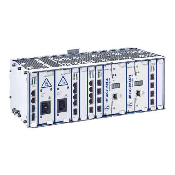
3. NODES – INSTALLATION FORMS 3.1 General The Dragon PTN portfolio consists of 4 different node types: XT-2210-A, XT-2209-A, XT-2206-A and XT-1104-A. All nodes are modular and made of stainless steel (EN A2 1.4016). The XT-2210-A and XT-2209-A nodes are 19” Rack mountable (standard equipped). The XT-1104-A and XT-2206-A are 19”... -
Page 24: Emc Springs
EMC Springs All modules that can be plugged into a Dragon PTN node are provided with EMC springs for better EMC behavior. These springs can be found at the side of the front panel of each module. Do not touch or bend these springs when unpacking the module, or inserting/removing it into/from the node. -
Page 25: Node Module Positions
(PE). When installing a Dragon PTN node, there must be at least 3 U free space below and above the node for ventilation. - Page 26 Node Support Module (3 U) PSU-1 Power supply unit 1 PSU-2 Power supply unit 2 IFM-1…IFM-4 Interface module 1…4 CSM-1 Central Switching Module 1 CSM-2 Central Switching Module 2 IFM-5…IFM-10 Interface module 5…10 Dragon PTN Installation and Operation Release 01 02/2018...
- Page 27 IFM-1 IFM-2 IFM-3 IFM-4 XT-2209-A PSU-1 PSU-2 IFM-1 IFM-2 IFM-3 CSM-1 CSM-2 IFM-5 IFM-6 IFM-7 IFM-8 IFM-9 IFM-10 XT-2210-A PSU-1 PSU-2 CSM-1 CSM-2 IFM-5 IFM-6 IFM-7 IFM-8 IFM-9 IFM-10 IFM-1 IFM-2 IFM-3 IFM-4 Dragon PTN Installation and Operation Release 01 02/2018...
-
Page 28: Xt-1104-A Node (942 228-001)
DIN rail. Attach the fixation clips, left and right of the node, to the DIN rail and use the screws to hold the clips in line. See pictures below. Dragon PTN Installation and Operation Release 01 02/2018... - Page 29 Push down bracket to lock/unlock Detail: node to/from DIN Rail PE: Protective Earth Lock washer Cable Socket Grounding Cable DIN Rail Eearthing Fixation Wire Points To Grounding Bar normal ‘DIN Rail kit’ PE: Protective Earth Dragon PTN Installation and Operation Release 01 02/2018...
- Page 30 2. Assemble the two 19” brackets to the node as shown in the picture below. of a single Use the supplied screws to fix the brackets to the node. (both brackets can node be assembled either left or right of the node) 19” Bracket 19” Bracket Dragon PTN Installation and Operation Release 01 02/2018...
- Page 31 6. Make sure that the front is easily accessible to connect the cables and supervision later on. Detail: PE: Protective Earth Lock washer Cable Socket Grounding Cable Eearthing Wire To Grounding Bar PE: Protective Earth Dragon PTN Installation and Operation Release 01 02/2018...
- Page 32 Do not install any other equipment directly above/under the node for ventilation reasons. Above and below the node, sufficient space (3 U) must be provided to guarantee a free air flow. Dragon PTN Installation and Operation Release 01 02/2018...
- Page 33 6. Make sure that the front is easily accessible to connect the cables and supervision later on. Detail: PE: Protective Earth Lock washer Cable Socket Grounding Cable Eearthing Wire To Grounding Bar PE: Protective Earth Dragon PTN Installation and Operation Release 01 02/2018...
-
Page 34: Xt-2206-A Node (942 228-002)
DIN rail. Attach the fixation clips, left and right of the node, to the DIN rail and use the screws to hold the clips in line. See pictures below. Dragon PTN Installation and Operation Release 01 02/2018... - Page 35 Push down bracket to lock/unlock Detail: node to/from DIN Rail PE: Protective Earth Lock washer Cable Socket Grounding Cable Eearthing DIN Rail Wire Fixation Points normal ‘DIN Rail kit’ To Grounding Bar PE: Protective Earth Dragon PTN Installation and Operation Release 01 02/2018...
- Page 36 Pull down bracket to lock/unlock node to/from DIN Rail Heavy Duty ‘DIN Rail kit’ Fixation Screw Fixation clip Dragon PTN Installation and Operation Release 01 02/2018...
- Page 37 5. Connect an earthing wire (yellow – green) 6 mm² to the cable socket of the XT-2206-A node, see picture below. Connect the other end of the earthing wire to the grounding copper bar of the rack. Dragon PTN Installation and Operation Release 01 02/2018...
- Page 38 6. Make sure that the front is easily accessible to connect the cables and supervision later on. Detail: PE: Protective Earth Lock washer Cable Socket Grounding Cable Eearthing Wire To Grounding Bar PE: Protective Earth Dragon PTN Installation and Operation Release 01 02/2018...
-
Page 39: Xt-2209-A Node (942 228-003)
4. Connect an earthing wire (yellow – green) 6 mm² to the cable socket of the XT-2209-A node, see pictures below. Connect the other end of the earthing wire to the grounding copper bar of the rack. Dragon PTN Installation and Operation Release 01 02/2018... - Page 40 Push down bracket to lock/unlock Detail: node to/from DIN Rail PE: Protective Earth Lock washer Cable Socket Grounding Cable DIN Rail Eearthing Fixation Wire Points normal ‘DIN Rail kit’ To Grounding Bar PE: Protective Earth Dragon PTN Installation and Operation Release 01 02/2018...
-
Page 41: Xt-2210-A Node (942 228-004)
4. Connect an earthing wire (yellow – green) 6 mm² to the cable socket of the XT-2210-A node, see pictures below. Connect the other end of the earthing wire to the grounding copper bar of the rack. Dragon PTN Installation and Operation Release 01 02/2018... - Page 42 Push down bracket to lock/unlock Detail: node to/from DIN Rail PE: Protective Earth Lock washer Cable Socket Grounding Cable DIN Rail Eearthing Fixation Wire Points normal ‘DIN Rail kit’ To Grounding Bar PE: Protective Earth Dragon PTN Installation and Operation Release 01 02/2018...
- Page 43 Power Supplies – Installation Forms Dragon PTN Installation and Operation Release 01 02/2018...
-
Page 44: Power Supplies - Installation Forms
4. POWER SUPPLIES – INSTALLATION FORMS PSU Types for Dragon PTN Nodes The XT-2210-A/XT-2209-A/XT-2206-A node can be equipped with two power supplies. The XT- 1104-A can only be equipped with one power supply. PSU-1 and/or PSU-2 convert the mains or battery input voltages to 12 VDC for the operating voltages of the node. -
Page 45: Psu Cables
DC PSU 3G x 2.5mm² unshielded cable (3m) with coding keys for DC PSU 88 to 942 256-104 300 VDC Cable (3m) to connect External DIN rail PoE PSU to the NSM-A 942 256-105 Dragon PTN Installation and Operation Release 01 02/2018... - Page 46 Some parts of the node can be extremely hot. Therefore, it is strongly advised to use only the front panel handles of the module (NSM, CSM, IFM & PSU), and not touching the PCB or any other parts, when removing it from the node Dragon PTN Installation and Operation Release 01 02/2018...
-
Page 47: It Grounding System
IT Grounding System A Dragon PTN node can be connected to an IT grounding system (standard EN60950-1) (see picture below). Power source Distribution cable Building boundary Equipment Separate Neutral and Protective Conductors Power source Distribution cable PE Building boundary Equipment... -
Page 48: Acp-A: 100-240 Vac ± 10 % - Psu (942 234-001)
4. Connect the power distribution to the PSU via the power cord and push until the connector is locked. 5. Label the power cord(s). 6. If necessary, the node can be powered on as described in §3.2. Dragon PTN Installation and Operation Release 01 02/2018... -
Page 49: Dcp-A: 18-60 Vdc Psu (942 234-002)
1. Take the 18-60 VDC PSU out of the antistatic bag. 2. Slide the PSU in the allocated slot of the node (see corresponding Node form). 3. VERY IMPORTANT: Tighten the PSU with the two fastening screws for optimal contact. Dragon PTN Installation and Operation Release 01 02/2018... - Page 50 4. Connect the power distribution via the power cord to the PSU and tighten the 2 screws for locking the power cord. 5. Label the power cord(s). 6. If necessary, the node can be powered on as described in §3.2. Dragon PTN Installation and Operation Release 01 02/2018...
-
Page 51: Dcp-B: 88-300 Vdc Psu (942 234-003)
3. VERY IMPORTANT: Tighten the PSU with the two fastening screws for optimal contact. The DC power supplies/cables have a coding profile or code keys to prevent that a wrong cable and voltage is plugged into the PSU. Dragon PTN Installation and Operation Release 01 02/2018... - Page 52 4. Connect the power distribution via the power cord to the PSU and tighten the 2 screws for locking the power cord. 5. Label the power cord(s). 6. If necessary, the node can be powered on as described in §3.2. Dragon PTN Installation and Operation Release 01 02/2018...
-
Page 53: Acpoe-A Din Rail Psu/100-240 Vac ± 10 % - 48 Vdc Din Rail Psu (942 235-001)
Screwdriver set, cable ties and cable tool set Equipment Antistatic wristband NSM-A Module in a Dragon PTN node / DCPoE-A DIN Rail PSU + Power cord (if not pre-installed) PoE Connector Cable: 942 256-105 Extra documentation can be found in chapter 15... - Page 54 (942 256-105) 100- 100- 56 VDC 56 VDC 9. If a second PSU is required, repeat steps 1 to 8. DC1 and DC2 support reverse polarity protection. 10. Label the power cord(s). Dragon PTN Installation and Operation Release 01 02/2018...
-
Page 55: Dcpoe-A Din Rail Psu/ 33-62 Vdc(In) - 56 Vdc(Out) Din Rail Psu (942 235-002)
Screwdriver set, cable ties and cable tool set Equipment Antistatic wristband NSM-A Module in a Dragon PTN node / DCPoE-A DIN Rail PSU + Power cord (if not pre-installed) PoE Connector Cable: 942 256-105 Extra documentation can be found in chapter 15... - Page 56 If it is necessary that the DCPoE-A PSU 942 235-002 must operate fully-loaded at 70°C, the PSU Cooling Wall must be directly mounted, without DIN Rail, on an aluminum/metal wall plate for cooling Plate reasons. The cooling area on the plate must be at least 360x360x2mm. See below. Dragon PTN Installation and Operation Release 01 02/2018...
- Page 57 Cooling wall plate Dragon PTN Installation and Operation Release 01 02/2018...
- Page 58 Node Support Modules - Installation Forms Dragon PTN Installation and Operation Release 01 02/2018...
-
Page 59: Node Support Modules - Installation Forms
5. NODE SUPPORT MODULES – INSTALLATION FORMS The NSM is required in every Dragon PTN node and performs following functions via its front panel: Status indication of PSU(s) and CSM(s); Status and connection of Digital I/O (I= Input; O=output); Status and connection of PoE Power inputs (redundant), only on NSM-A;... - Page 60 Output: DC 48-54V (factory set 48 V) DCPoE-A: External DIN Rail PSU (DIN Rail accessories 942 235-002 included) Input: DC 33 - 62V (=wide range) Output: DC 56V (factory set) PoE Cable 942 256-105 Dragon PTN Installation and Operation Release 01 02/2018...
-
Page 61: Nsm-A (942 229-001), Nsm-B (942 229-002)
0.4 lb Front Panel NSM-A NSM-B With PoE Connectors Without PoE Connectors Fastening screw Handle LEDs Hidden CSM Switch-over button Digital input (DI) ports Digital input (DO) ports PoE external power input Dragon PTN Installation and Operation Release 01 02/2018... - Page 62 D C 4 8 V 1 0 A D C 4 8 V 1 0 A + + - - + + - - PoE Connector Cable (942 256-105) 100- 100- 56 VDC 56 VDC Dragon PTN Installation and Operation Release 01 02/2018...
- Page 63 DCPoE PSU (942 235-002) 33-62 33-62 G = Ground 3 2 1 3 2 1 PoE Connector Cable (942 256-105) 56 VDC 56 VDC Dragon PTN Installation and Operation Release 01 02/2018...
- Page 64 S2 (=most significant) and MUST NOT BE CHANGED! A hidden CSM switch-over button (SW1) is available on the NSM to make a switch-over from the active to the redundant standby CSM (not applicable on the XT-1104-A node). Dragon PTN Installation and Operation Release 01 02/2018...
- Page 65 Example: Node N° = 219 Dec 0 2 1 9 Node Number Example 2. Status info via NSM-A LEDs: See node manual listed in §15 for more information on the NSM LEDs. Dragon PTN Installation and Operation Release 01 02/2018...
- Page 66 Central Switching Module – Installation Forms Dragon PTN Installation and Operation Release 01 02/2018...
-
Page 67: Central Switching Module - Installation Forms
Dragon PTN nodes via an Integrated Ethernet Multilayer Switch and Traffic Manager on board. All CSMs in the same Dragon PTN network must have the same firmware installed compatible with the installed HiProvision version. -
Page 68: Csm310-A (942 230-001)
1. Remove the ESD packaging from the CSM, do not touch or bend the EMC spring on the side of the front panel. 2. Identify the Dragon PTN node where the CSM has to be installed (see allocated slot below):... - Page 69 3. Set/hold the extractor handles unlocked or horizontal, in line with the top of the module. 4. Take the CSM with the front panel handles, aim correctly and slide the module through the two bottom/top card guides (see Dragon PTN Installation and Operation Release 01 02/2018...
- Page 70 4. Make sure that a Micro SD card is plugged in. Micro SD Card Hardware Heat Sink Interface Edition Lock Unlock Extractor Hidden Reset handle Button 5. Insert the CSM into the node (see the section below). Dragon PTN Installation and Operation Release 01 02/2018...
- Page 71 CSM in HiProvision. 2. In HiProvision, discover the network elements and links in the Dragon PTN Network. 3. In HiProvision, approve the Dragon PTN Network. 4. In HiProvision, configure all the network elements and links in the Dragon PTN Installation and Operation...
- Page 72 (see the section below). (CAUTION: Never pull out the active CSM). 3. DO NOT change the hardware edition DIP switch (S1). 4. Make sure that a Micro SD card is plugged in. Dragon PTN Installation and Operation Release 01 02/2018...
- Page 73 4. Inward push or lock the extractor handles. 5. Push firmly with your thumbs on the front panel for optimal backplane contact; 6. Tighten the four fastening screws. Dragon PTN Installation and Operation Release 01 02/2018...
- Page 74 1. Use your cell phone to communicate with the control center and ask them to program the CSM in HiProvision. 2. In HiProvision, discover the nodes and links in the Dragon PTN Network. 3. In HiProvision, approve the Dragon PTN Network.
- Page 75 Interface Modules – Installation Forms Dragon PTN Installation and Operation Release 01 02/2018...
-
Page 76: Interface Modules - Installation Forms
Shortcuts Manuals. See chapter 15 for details. https://hiprovision.hirschmann.com Dragon PTN nodes provide universal mounting positions for up to ten IFMs. Both low speed (1G) and high speed (10G) IFMs can be used together in the same node. In which slot the node can be plugged depends on the speed type (1G or 10G) of the IFM and the node type. -
Page 77: General Recommendations: Optical Connectors, Laser Diodes And Fibers
‘Dragon PTN and HiProvision Operation’ manual, see chapter 15. Interface modules can be removed from and inserted into the node while the power is on (hot swappable). Detailed installation forms with cable information of all common Dragon PTN interface modules are listed in this chapter. -
Page 78: 2-C37.94 (With E1: 942 236-009 / With T1: 942 236-010)
Interface cable(s) Extra documentation can be found in chapter 15 XT-1104-A/XT-2206-A/ Weight: approx. 0.22 kg Compatibility XT-2209-A/XT-2210-A / 0.5 lb Front Panel Fastening screw Handle LEDs 2 C37.94 Ports 2 E1/T1 Ports Dragon PTN Installation and Operation Release 01 02/2018... - Page 79 EMC spring on the side of the front panel. 2. The E1/T1 configuration of the 2-C37.94 module is factory set by the S1 DIP switch and must not be changed. The configuration can be read out via HiProvision. Dragon PTN Installation and Operation Release 01 02/2018...
- Page 80 2. In HiProvision, discover the network elements and links in the Dragon PTN Network. 3. In HiProvision, approve the Dragon PTN Network. 4. In HiProvision, configure all the network elements and links in the database. This could be done automatically via the discover and approve steps, or it can be done manually.
- Page 81 Color Codes, Pin Numbers, Signal Names Color Signal Name Pin Number Rx (Receive) RING WH/OG Rx (Receive) TIP Not connected Tx (Transmit) RING WH/BU Tx (Transmit) TIP Not connected Not connected Not connected Dragon PTN Installation and Operation Release 01 02/2018...
-
Page 82: 4-Dsl-Lw (942 236-007)
Extra documentation can be found in chapter 15 XT-1104-A/XT-2206-A/ Weight: approx. 0.25 kg Compatibility XT-2209-A/XT-2210-A / 0.6 lb Front Panel Fastening screw Handle LEDs Port 1, 2, 3, 4: SHDSL port Dragon PTN Installation and Operation Release 01 02/2018... - Page 83 5. Push firmly with your thumbs on the front panel for optimal backplane contact. 6. Tighten the two fastening screws. 7. Plug the interface cable(s) into the corresponding connector(s) (see next page(s) for pin numbers, signal names and color codes). Dragon PTN Installation and Operation Release 01 02/2018...
- Page 84 7. Check whether the links are up via the LEDs, info on the LEDs via manuals listed in §15. 8. Call the control center to check whether the 4-DSL-LW module is functioning properly after having it programmed in HiProvision. Dragon PTN Installation and Operation Release 01 02/2018...
- Page 85 2. In HiProvision, discover the network elements and links in the Dragon PTN Network. 3. In HiProvision, approve the Dragon PTN Network. 4. In HiProvision, configure all the network elements and links in the database. This could be done automatically via the discover and approve steps, or it can be done manually.
- Page 86 4-DSL-LW RJ-45 Connector: Pin Assignments Pin Number Description 1,2,3 Not Used Data Pair1 Tip (+), including wetting current if configured in HiProvision Data Pair1 Ring (-), including wetting current if configured in HiProvision 6,7,8 Not Used Dragon PTN Installation and Operation Release 01 02/2018...
-
Page 87: 4-E1-L/4-T1-L (942 236-010/ 942 236-011)
3. Take the 4-E1-L/4-T1-L module with the front panel handles, aim correctly and slide it through the correct card guides (see chapter §3.4) into the allocated slot. Dragon PTN Installation and Operation Release 01 02/2018... - Page 88 2. The E1/T1 configuration of the 4-E1-L/4-T1-L module is factory set by the S1 DIP switch and must not be changed. The configuration can be read out via HiProvision. E1/T1 Hardware Configuration Edition Dragon PTN Installation and Operation Release 01 02/2018...
- Page 89 2. In HiProvision, discover the network elements and links in the Dragon PTN Network. 3. In HiProvision, approve the Dragon PTN Network. 4. In HiProvision, configure all the network elements and links in the database. This could be done automatically via the discover and approve steps, or it can be done manually.
- Page 90 Color Codes, Pin Numbers, Signal Names Color Signal Name Pin Number Rx (Receive) RING WH/OG Rx (Receive) TIP Not connected Tx (Transmit) RING WH/BU Tx (Transmit) TIP Not connected Not connected Not connected Dragon PTN Installation and Operation Release 01 02/2018...
-
Page 91: 16-E1-L/16-T1-L (942 236-012/942 236-013)
3. Take the 16-E1-L/16-T1-L module with the front panel handles, aim correctly and slide it through the correct card guides (see chapter §3.4) into the allocated slot. Dragon PTN Installation and Operation Release 01 02/2018... - Page 92 HiProvision steps below in the control center. A full Module description of the steps below can be found in ‘Dragon PTN and HiProvision Operation’ manual, see chapter 15. 1. Use your cell phone to communicate with the control center and ask them to program the 16-E1-L/16-T1-L in HiProvision.
- Page 93 3. In HiProvision, approve the Dragon PTN Network. 4. In HiProvision, configure all the network elements and links in the database. This could be done automatically via the discover and approve steps, or it can be done manually. 5. In HiProvision, program tunnels;...
- Page 94 24 Ports Patch Panel, Feedthrough: E1 Cable RJ-45 (120 Ω) 942 256-203 942 256-204 942 256-201 RJ-45 Inline HPDB68 Connector RJ-45 Coupler Drop Cable to RJ-45 Connection Unplugged router teleprotection Drop Cable to RJ-45 Connection Plugged Dragon PTN Installation and Operation Release 01 02/2018...
- Page 95 Drop Cable to 16 RJ-45 + 16 ports RJ-45 to BNC-Coax Patch Panel: 942 256-205 Patch panel: RJ-45 BNC HPDB68 Connector RJ-45 Bottom Bottom Drop Cable via RJ-45 to BNC-Coax Connection Unplugged router teleprotection Drop Cable via RJ-45 to BNC-Coax Connection Plugged Dragon PTN Installation and Operation Release 01 02/2018...
- Page 96 E1/T1 RJ-45 Cable Connector: Pin Assignments Pin Number Description Cable Wire Colors Rx (Receive) RING Rx (Receive) TIP WH/OG Not connected Tx (Transmit) RING Tx (Transmit) TIP WH/BU 6, 7, 8 Not connected Dragon PTN Installation and Operation Release 01 02/2018...
- Page 97 Light blue / green T_TIP_P2 Light green / green T_RING_P2 Orange / red R_TIP_P1 Orange / white R_RING_P1 Orange / green T_TIP_P1 Grey / white T_RING_P1 (*) R = Receive / T = Transmit Dragon PTN Installation and Operation Release 01 02/2018...
-
Page 98: 8-Fxs (Future Support)
3. Take the 8-FXS module with the front panel handles, aim correctly and slide it through the correct card guides (see chapter §3.4) into the allocated slot. Dragon PTN Installation and Operation Release 01 02/2018... - Page 99 1. Use your cell phone to communicate with the control center and ask them to program the 8-FXS in HiProvision. 2. In HiProvision, discover the network elements and links in the Dragon PTN Network. 3. In HiProvision, approve the Dragon PTN Network. Dragon PTN Installation and Operation Release 01 02/2018...
- Page 100 Description Ordering Number 8-FXS Connection Kit future support Patch panel 1 U feedthrough 24 ports (to be used in combo with the 8-FXS Connection Kit) 942 256-204 Dragon PTN Installation and Operation Release 01 02/2018...
- Page 101 24 Ports Patch Panel, Feedthrough: Analog Telephone (future support) 942 256-204 RJ-11 Cable RJ-11 Inline RJ-45 Coupler port 1 port 4 port 5 port 8 8-FXS Connection: Unplugged 8-FXS Connection: Plugged 8-FXS RJ-45 Connector Dragon PTN Installation and Operation Release 01 02/2018...
- Page 102 RING4 brown White Blue TIP5 white/orange Green RING5 orange White Blue TIP6 white/green Green RING6 green White Blue TIP7 blue Green RING7 white/blue White Blue TIP8 white/brown Green RING8 brown White Blue Dragon PTN Installation and Operation Release 01 02/2018...
-
Page 103: 4-Gc-Lw (942 236-001), 4-Gcb-Lw (942 236-008)
3. Take the 4-GC-LW/4-GCB-LW module with the front panel handles, aim correctly and slide it through the correct card guides (see chapter §3.4) into the allocated slot. Dragon PTN Installation and Operation Release 01 02/2018... - Page 104 A trained HiProvision administrator must perform the 4-GC-LW/ HiProvision steps below in the control center. A full 4-GCB-LW description of the steps below can be found in Module ‘Dragon PTN and HiProvision Operation’ manual, see chapter 15. Dragon PTN Installation and Operation Release 01 02/2018...
- Page 105 2. In HiProvision, discover the network elements and links in the Dragon PTN Network. 3. In HiProvision, approve the Dragon PTN Network. 4. In HiProvision, configure all the network elements and links in the database. This could be done automatically via the discover and approve steps, or it can be done manually.
- Page 106 Cable (1000Base-T): Pin Numbers and Signal Names Signal Name Pin Number Dragon PTN Installation and Operation Release 01 02/2018...
-
Page 107: 7-Serial (942 236-014)
Extra documentation can be found in chapter 15 XT-1104-A/XT-2206-A/ Weight: Compatibility XT-2209-A/XT-2210-A approx. 0.24 kg / 0.5 lb Front Panel Fastening screw Handle LEDs 10 RJ.5 connectors Tx Data Rx Data Dragon PTN Installation and Operation Release 01 02/2018... - Page 108 HiProvision steps below in the control center. A full Module description of the steps below can be found in ‘Dragon PTN and HiProvision Operation’ manual, see chapter 15. 1. Use your cell phone to communicate with the control center and ask them to program the 7-SERIAL in HiProvision.
- Page 109 2. In HiProvision, discover the network elements and links in the Dragon PTN Network. 3. In HiProvision, approve the Dragon PTN Network. 4. In HiProvision, configure all the network elements and links in the database. This could be done automatically via the discover and approve steps, or it can be done manually.
- Page 110 The port mapping of the Basic and extension kit can be found in the tables below. The open end cables can be terminated to 10 pair terminal blocks. See below for more details. Dragon PTN Installation and Operation Release 01 02/2018...
- Page 111 Depending on the serial protocol standards and serial Port Role (DTE or DCE), the serial port has the signals as shown in the tables below. Each serial port [1,..,7] has 11 pins; Dragon PTN Installation and Operation Release 01 02/2018...
- Page 112 Serial Port – Pin n° Basic Kit WH/OG WH/GN WH/BU WH/BN WH/OG 1-10 WH/GN WH/BU WH/BN WH/OG WH/GN WH/BU WH/BN WH/OG 2-10 WH/GN WH/BU WH/BN WH/OG Frame GND WH/GN Frame GND Frame GND WH/BU WH/BN 3-10 Dragon PTN Installation and Operation Release 01 02/2018...
- Page 113 Serial Port – Pin n° Extension Kit 6 WH/OG WH/GN WH/BU WH/BN WH/OG 4-10 WH/GN WH/BU WH/BN WH/OG WH/GN WH/BU WH/BN WH/OG 6-10 WH/GN WH/BU WH/BN WH/OG WH/GN 5-10 WH/BU WH/BN 7-10 Dragon PTN Installation and Operation Release 01 02/2018...
- Page 114 RTSb CTSb (=combi) Out1- RTSa CTSa In1+ CTSb RTSb In1- CTSa RTSa Out2+ DTRb DSRb Out2- DTRa DSRa In2+ DSRb DTRb In2- DSRa DTRa In3/Out3+ DCDb(In) DCDb(Out) In3/Out3- DCDa(In) DCDa(Out) DCD(In) DCD(Out) Dragon PTN Installation and Operation Release 01 02/2018...
- Page 115 RJ.5 pin n° Block Pair WH/BN WH/BU WH/BN WH/BU WH/BN Color WH/OG WH/GN WH/BU WH/OG WH/GN Termination Signal TxC(In) DCD(In) TxC(In) DCD(In) block Port n° Serial Port 6 Serial Port 7 Ext.Eq. Dragon PTN Installation and Operation Release 01 02/2018...
- Page 116 Termination RxDb RxDa TxDb TxDa CTSb CTSa RTSb RTSa RxDb RxDa TxDb TxDa CTSb CTSa RTSb RTSa block Signal DCDb(Out) DCDa(Out) DCDb(Out) DCDa(Out) Port n° Serial Port 6 Serial Port 7 Ext.Eq. Dragon PTN Installation and Operation Release 01 02/2018...
- Page 117 WH/BN WH/OG WH/BU WH/BN WH/BU WH/BN WH/GN WH/GN Termination Tri-state Tri-state Tri-state Tri-state TRxDb TRxDa Tri-state Tri-state Tri-state Tri-state TRxDb TRxDa block Signal Port n° Serial Port 6 Serial Port 7 Ext.Eq. Dragon PTN Installation and Operation Release 01 02/2018...
- Page 118 RJ.5 pin n° Block Pair Color WH/OG WH/BU WH/BN WH/OG WH/BU WH/BN WH/BU WH/BN WH/GN WH/GN Termination TxDa block Signal TxDb RxDb RxDa Sb(In) Sa(In) Port n° Serial Port 6 Serial Port 7 Ext.Eq. Dragon PTN Installation and Operation Release 01 02/2018...
- Page 119 Termination RxDb RxDa TxDb TxDa RxCb RxCa TTCb TTCa RxDb RxDa TxDb TxDa RxCb RxCa TTCb TTCa block Signal TXCb(Out) TXCa(Out) TXCb(Out) TXCa(Out) Port n° Serial Port 6 Serial Port 7 Ext.Eq. Dragon PTN Installation and Operation Release 01 02/2018...
- Page 120 WH/GN WH/BU WH/BN WH/OG WH/GN WH/BU WH/BN WH/BU WH/BN Termination Signal RxDb RxDa TxDb TxDa RxCb RxCa TTCb TTCa block TXCb(Out) TXCa(Out) DCD(Out) Port n° Serial Port 6 Serial Port 7 Ext.Eq. Dragon PTN Installation and Operation Release 01 02/2018...
-
Page 121: 1-10G-Lw (942 236-004)
EMC spring on the side of the front panel. 2. Identify the node and the interface slot where the module has to be installed, see corresponding node form. Dragon PTN Installation and Operation Release 01 02/2018... - Page 122 4. Connect the optical fibers (LC connectors) to the XFP port (1) on the 1-10G-LW front panel. 5. Check the WPH and LA LED, info on the LEDs via manuals listed in §15. Dragon PTN Installation and Operation Release 01 02/2018...
- Page 123 2. In HiProvision, discover the network elements and links in the Dragon PTN Network. 3. In HiProvision, approve the Dragon PTN Network. 4. In HiProvision, configure all the network elements and links in the database. This could be done automatically via the discover and approve steps, or it can be done manually.
-
Page 124: 4-2/4Wem (Future Support)
Extra documentation can be found in chapter 15 Compatibility XT-1104-A/XT-2206-A/ Weight: approx. 0.24 kg XT-2209-A/XT-2210-A / 0.5 lb Front Panel Fastening screw Handle Spare LEDs Port 1, 2, 3, 4: 2/4WEM ports Dragon PTN Installation and Operation Release 01 02/2018... - Page 125 HiProvision steps below in the control center. A full Module description of the steps below can be found in ‘Dragon PTN and HiProvision Operation’ manual, see chapter 15. 1. Use your cell phone to communicate with the control center and ask them to program the 4-2/4WEM in HiProvision.
- Page 126 Dragon PTN Network. 3. In HiProvision, approve the Dragon PTN Network. 4. In HiProvision, configure all the network elements and links in the database. This could be done automatically via the discover and approve steps, or it can be done manually.
-
Page 127: 4-Codir (Future Support)
EMC spring on the side of the front panel. 2. Identify the node and the interface slot where the module has to be installed, see corresponding node form. Dragon PTN Installation and Operation Release 01 02/2018... - Page 128 2. In HiProvision, discover the network elements and links in the Dragon PTN Network. 3. In HiProvision, approve the Dragon PTN Network. 4. In HiProvision, configure all the network elements and links in the database. This could be done automatically via the discover and approve steps, or it can be done manually.
- Page 129 E1 cable (120 Ω): ordering number 942 256-201 RJ-45 Connector: Pin Assignments Pin Number Description Cable Wire Colors Rx (Receive) RING Rx (Receive) TIP WH/OG Not connected Tx (Transmit) RING Tx (Transmit) TIP WH/BU 6, 7, 8 Not connected Dragon PTN Installation and Operation Release 01 02/2018...
-
Page 130: 4-Go-Lw (942 236-002)
EMC spring on the side of the front panel. 2. Identify the node and the interface slot where the module has to be installed, see corresponding node form. Dragon PTN Installation and Operation Release 01 02/2018... - Page 131 4. Connect the optical fibers (LC connectors) to an SFP port on the 4-GO-LW front panel. 5. Check the W (1-4) and LA (1-4) LED, info on the LEDs via manuals listed in §15. Dragon PTN Installation and Operation Release 01 02/2018...
- Page 132 2. In HiProvision, discover the network elements and links in the Dragon PTN Network. 3. In HiProvision, approve the Dragon PTN Network. 4. In HiProvision, configure all the network elements and links in the database. This could be done automatically via the discover and approve steps, or it can be done manually.
-
Page 133: 2-Ols (With E1: Future Support / With T1: Future Support)
EMC spring on the side of the front panel. 2. Identify the node and the interface slot where the module has to be installed, see corresponding node form. Dragon PTN Installation and Operation Release 01 02/2018... - Page 134 HiProvision steps below in the control center. A full Module description of the steps below can be found in ‘Dragon PTN and HiProvision Operation’ manual, see chapter 15. 1. Use your cell phone to communicate with the control center and ask them to program the 2-OLS in HiProvision.
- Page 135 2. In HiProvision, discover the network elements and links in the Dragon PTN Network. 3. In HiProvision, approve the Dragon PTN Network. 4. In HiProvision, configure all the network elements and links in the database. This could be done automatically via the discover and approve steps, or it can be done manually.
-
Page 136: 9-L3A-L (942 236-005)
IFM[8,9], [9,10]: Limited operation, 4 Gbps bandwidth (4*1G), no 10G; Other nodes: IFM[1,2], [2,3], [3,4], [9,10]: Limited operation, 4 Gbps bandwidth (4*1G), no 10G; IFM[5,6], [6,7], [7,8], [8,9]: Limited operation, 1 Gbps bandwidth (1*1G), no 10G; Dragon PTN Installation and Operation Release 01 02/2018... - Page 137 Always wear an antistatic wristband in direct contact 10 min. with your skin. Connect the alligator clip to the blank metal of the rack or plug the antistatic wristband into the ESD bonding point. Dragon PTN Installation and Operation Release 01 02/2018...
- Page 138 2. In HiProvision, discover the network elements and links in the Dragon PTN Network. 3. In HiProvision, approve the Dragon PTN Network. 4. In HiProvision, configure all the network elements and links in the database. This could be done automatically via the discover and approve steps, or it can be done manually.
-
Page 139: Optical Transceiver/Receiver Modules (Sfp, Xfp)
ESD bonding point. Installation Key of the rack (if necessary) Equipment Screwdriver set Antistatic wristband SFP, XFP modules delivered by Hirschmann Extra documentation can be found in chapter 15 Plug in 1. Consult your optical network drawing to Ejector clip SFP/XFP... - Page 140 Cables Dragon PTN Installation and Operation Release 01 02/2018...
-
Page 141: Cables
The table below provides an overview of the color codes of the cables according to IEC 757. Color Code Color Color Code Color Black Blue Orange Yellow Violet Green Pink Brown Turquoise Slate Silver White Dragon PTN Installation and Operation Release 01 02/2018... - Page 142 Add New Node to a Live Network Dragon PTN Installation and Operation Release 01 02/2018...
-
Page 143: Add New Node To A Live Network
10. Approve the discovered node and links in the Discovery tile; 11. Auto create the new node and links in the database in the Discovery tile; 12. Your node is ready to participate in the Dragon PTN network. Services can be created on the plugged in IFMs. - Page 144 Installation File Dragon PTN Installation and Operation Release 01 02/2018...
-
Page 145: Installation File
Data with respect to the optical distribution frame. Optical network and cabling plan. Power supply data, if any. Layout of the racks with the nodes. 10.1 Optical Power Measurements Node number Tx (dBm) Rx(dBm) Dragon PTN Installation and Operation Release 01 02/2018... - Page 146 Third-Party Equipment Dragon PTN Installation and Operation Release 01 02/2018...
-
Page 147: Third-Party Equipment
11. THIRD-PARTY EQUIPMENT Besides all the Dragon PTN equipment, add detailed installation instructions of possible third-party equipment to this manual. Dragon PTN Installation and Operation Release 01 02/2018... - Page 148 Repair Dragon PTN Installation and Operation Release 01 02/2018...
-
Page 149: Repair
12. REPAIR Information on the handling of complaints can be found on the Internet: http://www.beldensolutions.com/en/Service/Repairs/index.phtml Dragon PTN Installation and Operation Release 01 02/2018... - Page 150 Final Installation Activities Dragon PTN Installation and Operation Release 01 02/2018...
-
Page 151: Final Installation Activities
On completion of the installation of the Dragon PTN equipment, perform the following actions. Step no. Description Wipe all surfaces of the Dragon PTN rack, to remove any dirt, grease or blemishes Close and lock the door of the rack Sweep and tidy the work area... - Page 152 Preventive Maintenance Dragon PTN Installation and Operation Release 01 02/2018...
-
Page 153: Preventive Maintenance
Check the rack, if installed outdoor, for possible water leakages or other failings. Check the power distribution fuses, circuit breakers and earthing connection of the node(s). Check that all cables are properly attached to the Dragon PTN equipment and that the minimum bending radius for all cables is respected. -
Page 154: Test Ups
& copper connections 14.8 Repair Stock Check the stock of Dragon PTN spare parts on a yearly base and order extra parts if necessary. Keep an MTBF report of the installed network. 14.9 Health Check and System Upgrade Make sure to update the operating system and firewall of the HiProvision server on a regular base. - Page 155 Reference List Dragon PTN Installation and Operation Release 01 02/2018...
-
Page 156: Manuals Reference List
15. MANUALS REFERENCE LIST All these manuals can be found in the HiProvision (=Dragon PTN Management System) Help function or on the Portal (=https://hiprovision.hirschmann.com) Manual Reference number Products (&=language code; *=issue) General (Software + Hardware) Dragon PTN and HiProvision Operation DRA-DRM821-&-*... - Page 157 Abbreviations List Dragon PTN Installation and Operation Release 01 02/2018...
-
Page 158: Abbreviations List
Power Supply Input Power Supply Output Power Supply Unit Packet Transport Network Remote Defect Indication Return Merchandise Authorization Synchronous Digital Hierarchy Small Form-factor Pluggable SHDSL Symmetrical High Bitrate Digital Subscriber Line Transmit Receive Module Dragon PTN Installation and Operation Release 01 02/2018... - Page 159 Uninterruptable Power Supply Wide Area Network WEEE Waste of Electrical and Electronic Equipment WAN PHY, Packet Over SDH Dragon PTN Installation and Operation Release 01 02/2018...
- Page 160 General Node Data Dragon PTN Installation and Operation Release 01 02/2018...
-
Page 161: General Node Data
= not available in XT-1104-A = not available in XT-1104-A and XT-2206-A = not available in XT-2209-A NSM: Node Support Module / IFM: Interface Module / PSU: Power Supply Unit / CSM: Central Switching Module Dragon PTN Installation and Operation Release 01 02/2018... - Page 162 ESD Recommendations Dragon PTN Installation and Operation Release 01 02/2018...
-
Page 163: Esd Recommendations
Printed circuits sensitive to static discharges shall be clearly marked to indicate that they are to be handled with care at all times. Hirschmann selected as their warning label the international ‘EIA’ symbol on a yellow background, represented in the figure below. - Page 164 Anti-static inner layer All conductive or static protective packaging’s used to contain ESD modules shall be clearly marked with the ESD label or the EIA label as represented in the figure below. EIA Label Dragon PTN Installation and Operation Release 01 02/2018...
-
Page 165: Handling Of Esd Modules
Anti-static work clothes consisting of (at least) 50 % cotton or equivalent fabric; static charge caused by friction shall be < 100 V. Grounded wrist strap, with incorporated resistor for personal protection, contacting both skin and ground. Dragon PTN Installation and Operation Release 01 02/2018... -
Page 166: Protective Guidelines For Workshop Equipment
Storage of ESD Modules ESD modules are to be kept in their original static protective packaging. 18.5 Transportation of ESD Modules ESD modules NEED to be transported in their static protective packaging. Dragon PTN Installation and Operation Release 01 02/2018... -
Page 167: Handling And Transportation Of Racks And Systems
Handle the modules by the edges only. j. Avoid contact with connector tabs and components on the module. k. Avoid contact between the module and plastics or textiles. Dragon PTN Installation and Operation Release 01 02/2018...
Need help?
Do you have a question about the Dragon PTN and is the answer not in the manual?
Questions and answers