Table of Contents
Advertisement
Quick Links
Atmel MCUs
I/O1 Xplained Pro
USER GUIDE
Preface
®
Atmel
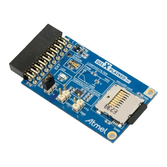
I/O1 Xplained Pro is an extension board to the Atmel Xplained Pro
evaluation platform. I/O1 Xplained Pro is designed to give a wide variety of
functionality to Xplained Pro MCU boards including a microSD card, a
temperature sensor, a light sensor, and more.
Atmel-42078B-IO1-Xplained-Pro_User Guide-10/2015
Advertisement
Table of Contents

Related Manuals for Atmel I/O1 Xplained Pro


Summary of Contents for Atmel I/O1 Xplained Pro
-
Page 1: Preface
Atmel I/O1 Xplained Pro is an extension board to the Atmel Xplained Pro evaluation platform. I/O1 Xplained Pro is designed to give a wide variety of functionality to Xplained Pro MCU boards including a microSD card, a temperature sensor, a light sensor, and more. -
Page 2: Table Of Contents
4.3.5. Light Sensor......................... 11 5. Hardware Revision History and Known Issues............12 5.1. Identifying Product ID and Revision................... 12 5.2. Revision 3...........................12 6. Document Revision History..................13 7. Evaluation Board/kit Important Notice..............14 Atmel I/O1 Xplained Pro [USER GUIDE] Atmel-42078B-IO1-Xplained-Pro_User Guide-10/2015... -
Page 3: Introduction
1.2. Kit Overview Atmel I/O1 Xplained Pro extension board is a generic extension board for the Xplained Pro platform. It connects to any Xplained Pro standard extension header on any Xplained Pro MCU board. The extension board utilizes all functions on the standard Xplained Pro extension header to further enhance the feature set of Xplained Pro MCU boards. -
Page 4: Getting Started
, Windows 7, and Windows 8. Once the Xplained Pro MCU board is powered the green power LED will be lit and Atmel Studio will auto detect which Xplained Pro MCU- and extension board(s) are connected. Atmel Studio will present relevant information like datasheets and kit documentation. -
Page 5: Xplained Pro
When an Xplained Pro extension is connected to an Xplained Pro MCU board the information is read and sent to Atmel Studio. The Atmel Kits extension, installed with Atmel Studio, will give relevant information, code examples, and links to relevant documents. - Page 6 SPI_MISO Master in slave out line of serial peripheral interface. Always implemented, bus type. SPI_SCK Clock for serial peripheral interface. Always implemented, bus type. Ground Power for extension board Atmel I/O1 Xplained Pro [USER GUIDE] Atmel-42078B-IO1-Xplained-Pro_User Guide-10/2015...
-
Page 7: Hardware User Guide
4.1. Electrical Characteristics I/O1 Xplained Pro can be connected to several Xplained Pro MCU boards and manually connected to other hardware. Xplained Pro MCU board(s) that does not have 3.3V as it's primary target voltage will read all ID devices on connected extensions to check if they support the target voltage before enabling it to the extension headers. -
Page 8: Power Header
VTG for target voltage and GND for ground. Info: The two pin power header should not be used to apply power to I/O1 Xplained Pro when connected to an Xplained Pro MCU board as it will get power from the Xplained Pro MCU board through the 20-pin extension connector. -
Page 9: Uart Header
Peripherals 4.3.1. There is one yellow LED available on the I/O1 Xplained Pro extension board that can be controlled by Pulse Width Modulation (PWM) or regular GPIO operation. The LED can be activated by driving the connected I/O line to GND. -
Page 10: Microsd Card Connector
100kΩ resistors, which makes the default addresses 0b1001111 and 0b1010111. Soldering the straps on the back of the I/O1 Xplained Pro board for An will alter that bit in the address to zero. Each strap is marked in silkscreen with A0, A1, and A2 as shown in the picture below. When communicating with the EEPROM parts of the TWI address is used as a page address. -
Page 11: Light Sensor
Vishay. The sensor data can be read by an ADC pin on n Xplained Pro MCU board. Table 4-10 Light Sensor Connections Pin on EXT connector Function Light sensor signal Atmel I/O1 Xplained Pro [USER GUIDE] Atmel-42078B-IO1-Xplained-Pro_User Guide-10/2015... -
Page 12: Hardware Revision History And Known Issues
5.1. Identifying Product ID and Revision The revision and product identifier of Xplained Pro boards can be found in two ways; either through Atmel Studio or by looking at the sticker on the bottom side of the PCB. By connecting an Xplained Pro MCU board to a computer with Atmel Studio running, an information window will pop up. -
Page 13: Document Revision History
Document Revision History Doc. rev. Date Comment 42078B 10/2015 Added electrical characteristics 42078A 02/2013 Initial document release Atmel I/O1 Xplained Pro [USER GUIDE] Atmel-42078B-IO1-Xplained-Pro_User Guide-10/2015... -
Page 14: Evaluation Board/Kit Important Notice
(WEEE), FCC, CE or UL (except as may be otherwise noted on the board/kit). Atmel supplied this board/kit "AS IS," without any warranties, with all faults, at the buyer's and further users' sole risk. The user assumes all responsibility and liability for proper and safe handling of the goods. - Page 15 DISCLAIMER: The information in this document is provided in connection with Atmel products. No license, express or implied, by estoppel or otherwise, to any intellectual property right is granted by this document or in connection with the sale of Atmel products. EXCEPT AS SET FORTH IN THE ATMEL TERMS AND...
- Page 16 Mouser Electronics Authorized Distributor Click to View Pricing, Inventory, Delivery & Lifecycle Information: Atmel ATIO1-XPRO...
Need help?
Do you have a question about the I/O1 Xplained Pro and is the answer not in the manual?
Questions and answers