Table of Contents
Advertisement
Quick Links
Advertisement
Table of Contents

Related Manuals for Lattice Semiconductor ASC Bridge Board


Summary of Contents for Lattice Semiconductor ASC Bridge Board
- Page 1 ASC Bridge Board Evaluation Board User Guide FPGA-EB-02025-2.0 September 2018...
-
Page 2: Table Of Contents
Figure A.4. Fan Connectors ..............................18 © 2015-2018 Lattice Semiconductor Corp. All Lattice trademarks, registered trademarks, patents, and disclaimers are as listed at www.latticesemi.com/legal. All other brand or product names are trademarks or registered trademarks of their respective holders. The specifications and information herein are subject to change without notice. - Page 3 Table D.4. Miscellaneous – ECP5 Versa Development Board and ASC Bridge Board Connections ........23 © 2015-2018 Lattice Semiconductor Corp. All Lattice trademarks, registered trademarks, patents, and disclaimers are as listed at www.latticesemi.com/legal. All other brand or product names are trademarks or registered trademarks of their respective holders. The specifications and information herein are subject to change without notice.
-
Page 4: Acronyms In This Document
Pulse Width Modulation © 2015-2018 Lattice Semiconductor Corp. All Lattice trademarks, registered trademarks, patents, and disclaimers are as listed at www.latticesemi.com/legal. All other brand or product names are trademarks or registered trademarks of their respective holders. The specifications and information herein are subject to change without notice. -
Page 5: Introduction
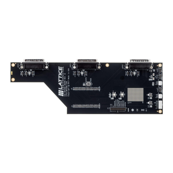
Evaluation Board User Guide 1. Introduction This guide describes the ASC Bridge Board, an interface board that connects up to three ASC Breakout Boards to either the MachXO3™-9400 Development Board or the ECP5™ Versa Development board for rapid prototyping and testing platform and hardware management applications. Throughout this document, the phrase ASC Breakout Board refers to a Platform Manager 2 evaluation board that is known by several names. -
Page 6: Features
Figure 2.1. MachXO3-9400 Evaluation Board Connected to the Three ASC Breakout Boards © 2015-2018 Lattice Semiconductor Corp. All Lattice trademarks, registered trademarks, patents, and disclaimers are as listed at www.latticesemi.com/legal. All other brand or product names are trademarks or registered trademarks of their respective holders. The specifications and information herein are subject to change without notice. -
Page 7: Setting Up The Board
3. Setting Up the Board To set up the board: Attach four of the included nylon standoffs to the ASC Bridge Board (only one standoff is needed at the narrow edge of the board). Attach two of the included nylon standoffs to the outside edge of each ASC Breakout Board. -
Page 8: Electrical, Mechanical, And Environmental Specifications
J2 and J3 are 40-pin female headers that connect the signals from either the MachXO3-9400 Development Board or the ECP5 Versa Development Board to the ASC Bridge Board. The female header carries both signal and power. The connections for J2 and J3 are listed in... -
Page 9: Table 8.2. J13 D-Sub 25 Connection
— © 2015-2018 Lattice Semiconductor Corp. All Lattice trademarks, registered trademarks, patents, and disclaimers are as listed at www.latticesemi.com/legal. All other brand or product names are trademarks or registered trademarks of their respective holders. The specifications and information herein are subject to change without notice. -
Page 10: Table 8.3. J7 D-Sub 25 Connection
— © 2015-2018 Lattice Semiconductor Corp. All Lattice trademarks, registered trademarks, patents, and disclaimers are as listed at www.latticesemi.com/legal. All other brand or product names are trademarks or registered trademarks of their respective holders. The specifications and information herein are subject to change without notice. -
Page 11: J1 Male Header
© 2015-2018 Lattice Semiconductor Corp. All Lattice trademarks, registered trademarks, patents, and disclaimers are as listed at www.latticesemi.com/legal. All other brand or product names are trademarks or registered trademarks of their respective holders. The specifications and information herein are subject to change without notice. -
Page 12: J16 Fan 1 Header
2-3 location. A hold-up capacitor is inserted in parallel with the fan to guarantee proper under speed detection. The ASC Bridge Board has a set of pre-populated capacitors connected through jumper J18. For fan PWM frequency less than 10 kHz, connect J18 to the 1-2 location. Connect J18 to the 2-3 location for fan PWM frequency between 10 kHz to 26.7 kHz. -
Page 13: Push Buttons
14. LED Indicators The D1 blue LED illuminates when 3.3 V power is applied to the ASC Bridge Board. The red LEDs, D2, D3, and D4 illuminate when the corresponding ASC Breakout Boards are installed on the ASC0, ASC1 or ASC2 connectors. -
Page 14: References
Submit a technical support case through www.latticesemi.com/techsupport. © 2015-2018 Lattice Semiconductor Corp. All Lattice trademarks, registered trademarks, patents, and disclaimers are as listed at www.latticesemi.com/legal. All other brand or product names are trademarks or registered trademarks of their respective holders. The specifications and information herein are subject to change without notice. -
Page 15: Appendix A. Board Schematics
Figure A.1. ASC Bridge Board Block Diagram © 2015-2018 Lattice Semiconductor Corp. All Lattice trademarks, registered trademarks, patents, and disclaimers are as listed at www.latticesemi.com/legal. All other brand or product names are trademarks or registered trademarks of their respective holders. The specifications and information herein are subject to change without notice. -
Page 16: Figure A.2. Ecp5 Connection
Figure A.2. ECP5 Connection © 2015-2018 Lattice Semiconductor Corp. All Lattice trademarks, registered trademarks, patents, and disclaimers are as listed at www.latticesemi.com/legal. All other brand or product names are trademarks or registered trademarks of their respective holders. The specifications and information herein are subject to change without notice. -
Page 17: Figure A.3. Asc Connection
Figure A.3. ASC Connection © 2015-2018 Lattice Semiconductor Corp. All Lattice trademarks, registered trademarks, patents, and disclaimers are as listed at www.latticesemi.com/legal. All other brand or product names are trademarks or registered trademarks of their respective holders. The specifications and information herein are subject to change without notice. -
Page 18: Figure A.4. Fan Connectors
Figure A.4. Fan Connectors © 2015-2018 Lattice Semiconductor Corp. All Lattice trademarks, registered trademarks, patents, and disclaimers are as listed at www.latticesemi.com/legal. All other brand or product names are trademarks or registered trademarks of their respective holders. The specifications and information herein are subject to change without notice. -
Page 19: Appendix B. Bill Of Materials
Machine Screw © 2015-2018 Lattice Semiconductor Corp. All Lattice trademarks, registered trademarks, patents, and disclaimers are as listed at www.latticesemi.com/legal. All other brand or product names are trademarks or registered trademarks of their respective holders. The specifications and information herein are subject to change without notice. -
Page 20: Appendix C. Machxo3 9400 Development Board And Asc Bridge Board Signals And Connections
User Defined © 2015-2018 Lattice Semiconductor Corp. All Lattice trademarks, registered trademarks, patents, and disclaimers are as listed at www.latticesemi.com/legal. All other brand or product names are trademarks or registered trademarks of their respective holders. The specifications and information herein are subject to change without notice. -
Page 21: Table C.4. Miscellaneous - Machxo3-9400 Development Board And Asc Bridge Board Connections
J10 or Y2 Oscillator. © 2015-2018 Lattice Semiconductor Corp. All Lattice trademarks, registered trademarks, patents, and disclaimers are as listed at www.latticesemi.com/legal. All other brand or product names are trademarks or registered trademarks of their respective holders. The specifications and information herein are subject to change without notice. -
Page 22: Appendix D. Ecp5 Versa Development Board And Asc Bridge Board Signals And Connections
User Defined © 2015-2018 Lattice Semiconductor Corp. All Lattice trademarks, registered trademarks, patents, and disclaimers are as listed at www.latticesemi.com/legal. All other brand or product names are trademarks or registered trademarks of their respective holders. The specifications and information herein are subject to change without notice. -
Page 23: Table D.4. Miscellaneous - Ecp5 Versa Development Board And Asc Bridge Board Connections
BANK_2P (U13 pin 27). © 2015-2018 Lattice Semiconductor Corp. All Lattice trademarks, registered trademarks, patents, and disclaimers are as listed at www.latticesemi.com/legal. All other brand or product names are trademarks or registered trademarks of their respective holders. The specifications and information herein are subject to change without notice. -
Page 24: Revision History
Initial release © 2015-2018 Lattice Semiconductor Corp. All Lattice trademarks, registered trademarks, patents, and disclaimers are as listed at www.latticesemi.com/legal. All other brand or product names are trademarks or registered trademarks of their respective holders. The specifications and information herein are subject to change without notice. - Page 25 Floor, 111 SW 5 Avenue Portland, OR 97204, USA T 503.268.8000 www.latticesemi.com...
Need help?
Do you have a question about the ASC Bridge Board and is the answer not in the manual?
Questions and answers