Table of Contents
Advertisement
Quick Links
Advertisement
Table of Contents

Related Manuals for MSI 865P Neo


Summary of Contents for MSI 865P Neo
- Page 1 865P Neo MS-6742 (v1.X) ATX Mainboard Version 1.0 G52-M6742X1-K01...
-
Page 2: Fcc-B Radio Frequency Interference Statement
Manual Rev: 1.0 Release Date: March 2003 FCC-B Radio Frequency Interference Statement This equipment has been tested and found to comply with the limits for a class B digital device, pursuant to part 15 of the FCC rules. These limits are designed to provide reasonable protection against harmful interference when the equipment is operated in a commercial environment. -
Page 3: Copyright Notice
Copyright Notice The material in this document is the intellectual property of MICRO-STAR INTERNATIONAL. We take every care in the preparation of this document, but no guarantee is given as to the correctness of its contents. Our products are under continual improvement and we reserve the right to make changes without notice. -
Page 4: Safety Instructions
Safety Instructions Always read the safety instructions carefully. Keep this User’s Manual for future reference. Keep this equipment away from humidity. Lay this equipment on a reliable flat surface before setting it up. The openings on the enclosure are for air convection hence protects the equipment from overheating. -
Page 5: Table Of Contents
Safety Instructions ..................v Chapter 1. Getting Started ................ 1-1 Mainboard Specifications ..............1-2 Mainboard Layout ................1-4 MSI Special Features ................1-5 Fuzzy Logic™ 4 ................1-5 Live BIOS™/Live Driver™ ............1-7 Live Monitor™ ................1-7 PC Alert™ 4 ................... 1-8 D-Bracket (Optional) .............. - Page 6 Keyboard Connector ..............2-11 USB Connectors ................2-11 Serial Port Connectors: COM A and COM B ....... 2-12 LAN (RJ-45) Jacks: 10/100 LAN ..........2-12 Audio Port Connectors ............... 2-13 Parallel Port Connector: LPT1 ............2-14 Connectors ..................2-15 Floppy Disk Drive Connector: FDD1 ........... 2-15 Fan Power Connectors: CPUFAN1/SYSFAN1/CHFAN1 .....
- Page 7 Standard CMOS Features ..............3-6 Advanced BIOS Features ..............3-8 Advanced Chipset Features ............... 3-13 Power Management Features ............. 3-16 PNP/PCI Configurations ..............3-20 Integrated Peripherals ................ 3-23 PC Health Status ................3-26 Frequency/Voltage Control ..............3-27 Set Supervisor/ User Password ............3-29 Load Optimized/Fail-Safe Defaults .............
-
Page 8: Chapter 1. Getting Started
Getting Started Chapter 1. Getting Started Getting Started Thank you for choosing the 865P Neo (MS-6742) v1.X ® ATX mainboard. The 865P Neo is based on Intel 865P and ICH4 chipsets for optimal system efficiency. Designed to fit the ®... -
Page 9: Mainboard Specifications
MS-6742 ATX Mainboard Mainboard Specifications ® Supports Intel P4 Northwood (Socket 478) processors. FSB 533MHz/800MHz (over chipset spec) depending on the North Bridge integrated. Supports up to 3.06GHz or higher speed P4 processor. Chipset ® Intel 865P chipset - Supports 400/533/800MHz Intel NetBurst micro-architecture bus. (FSB 800 MHz please refer to p.B-1 for details). - Page 10 Getting Started - Supports PIO, Bus Master operation modes. - Can connect up to four Ultra ATA drives. On-Board Peripherals On-Board Peripherals include: - 1 floppy port supports 2 FDDs with 360K, 720K, 1.2M, 1.44M and 2.88Mbytes - 2 serial ports COM1 & COM2 - 1 VGA port (Optional) - 1 parallel port supports SPP/EPP/ECP mode - 6 USB 2.0 ports (Rear * 4/ Front * 2)
-
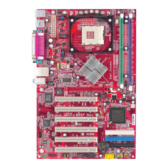
Page 11: Mainboard Layout
PCI Slot 3 ICH 4 Realtek RTL8101L (Optional) PCI Slot 4 IDE 2 PCI Slot 5 IDE 1 Codec PCI Slot 6 BATT FDD1 JB AT1 JFP1 JFP2 JSP4 JSP1 JA UD1 JD B1 JU SB2 865P Neo (MS-6742 v1.X) ATX Mainboard... -
Page 12: Msi Special Features
After rebooting, click Turbo to apply the test result. Click Default to restore the default values. Features: MSI Logo links to the MSI Web site CPU Speed allows users to adjust the CPU speed through CPU Multiplier and FSB... -
Page 13: Live Bios™/Live Driver
BIOS/drivers online so that you don’t need to search for the correct BIOS/driver version throughout the Web site. To use the function, you need to install the “MSI Live Update 2” application. After installation, the “MSI Live Update 2” icon (as shown on the right) will appear on the screen. -
Page 14: Live Monitor
Live Monitor™ The Live Monitor™ is a tool used to schedule the search for the latest BIOS/drivers version on the MSI Web site. To use the function, you need to install the “MSI Live Update 2” application. After installation, the “MSI Live Monitor” icon (as shown on the right) will appear on the screen. -
Page 15: Pc Alert™ 4
MS-6742 ATX Mainboard PC Alert™ 4 The PC Alert 4 is a utility you can find in the CD-ROM disk. The utility is just like your PC doctor that can detect the following PC hardware status during real time operation: monitor CPU &... - Page 16 CPU and chipset. Right-click the mouse to select the skin you want to switch to. Cute MSI Reminds You... 1. The new feature COOLER XP will work only if your mainboard supports AMD Athlon XP CPU.
-
Page 17: D-Bracket (Optional)
MS-6742 ATX Mainboard D-Bracket™ 2 (Optional) D-Bracket™ 2 is a USB bracket integrating four Diagnostic LEDs, which use graphic signal display to help users understand their system. The LEDs provide up to 16 combinations of signals to debug the system. The 4 LEDs can detect all problems that fail the system, such as VGA, RAM or other failures. - Page 18 Getting Started D-Bracket™ 2 Description Processor Initialization - This will show information regarding the processor (like brand name, system bus, etc…) Testing RTC (Real Time Clock) Initializing Video Interface - This will start detecting CPU clock, checking type of video onboard.
-
Page 19: S-Bracket (Optional)
MS-6742 ATX Mainboard S-Bracket (Optional) S-Bracket is a bracket which provides 2 SPDIF jacks for digital audio transmission and 2 analog Line-Out connectors for additional 4-channel analog audio output. With the S-Bracket, your system will be able to perform 6- channel audio operation for wonderful surround sound effect, or connect to Sony &... -
Page 20: Chapter 2. Hardware Setup
Hardware Setup Chapter 2. Hardware Setup Hardware Setup This chapter tells you how to install the CPU, memory modules, and expansion cards, as well as how to setup the jumpers on the mainboard. Also, it provides the instructions on connecting the peripheral devices, such as the mouse, keyboard, etc. -
Page 21: Quick Components Guide
MS-6742 ATX Mainboard Quick Components Guide CPUFAN1, p.2-16 CPU, p.2-3 ATX1, p.2-9 DDR DIMMs, p.2-7 Back Panel I/O, p.2-10 JPW1, p.2-9 CHFAN1, p.2-16 AGP Slot, p.2-26 SYSFAN1, p.2-16 PCI Slots, p.2-26 CD1, p.2-18 IDE1, IDE2, p.2-17 FDD1, p.2-15 JFP1, p.2-20 JSP4, p.2-25 JFP2, p.2-20 JSP1, p.2-18... -
Page 22: Central Processing Unit: Cpu
CPU core speed Host Clock x Core/Bus ratio 100MHz x 16 1.6 GHz MSI Reminds You... Overheating Overheating will seriously damage the CPU and system, always make sure the cooling fan can work properly to protect the CPU from overheating. -
Page 23: Cpu Installation Procedures For Socket 478
MS-6742 ATX Mainboard CPU Installation Procedures for Socket 478 Please turn off the power and unplug the power cord before Open Lever installing the CPU. Pull the lever sideways away Sliding 90 degree Plate from the socket. Make sure to raise the lever up to a 90- degree angle. -
Page 24: Installing The Cpu Fan
Hardware Setup Installing the CPU Fan As processor technology pushes to faster speeds and higher performance, thermal management becomes increasingly important. To dissipate heat, you need to attach the CPU cooling fan and heatsink on top of the CPU. Follow the instructions below to install the Heatsink/Fan: Locate the CPU and its retention Position the heatsink onto the reten-... - Page 25 MS-6742 ATX Mainboard Connect the fan power cable from the mounted fan to the 3-pin fan power connector on the board. fan power cable NOTES...
-
Page 26: Memory
Hardware Setup Memory The mainboard provides 2 slots for 184-pin, 2.5V DDR DIMM modules and supports the memory size up to 2 GB without ECC,. You can install DDR266/ DDR333 DDR SDRAM modules on the DDR DIMM slots. To operate properly, at least one DIMM module must be installed. -
Page 27: Ddr Dimm Module Combination
2. Insert the DIMM memory module vertically into the DIMM slot. Then push it in until the golden finger on the memory module is deeply in- serted in the socket. MSI Reminds You... You can barely see the golden finger if the module is properly inserted in the socket. -
Page 28: Power Supply
Hardware Setup Power Supply The mainboard supports ATX power supply for the power system. Be- fore inserting the power supply connector, always make sure that all compo- nents are installed properly to ensure that no damage will be caused. ATX 20-Pin Power Connector: ATX1 This connector allows you to connect to an ATX power supply. -
Page 29: Back Panel
MS-6742 ATX Mainboard Back Panel The back panel provides the following connectors: L-in Parallel (Optional) Mouse USB Ports L-out Keyboard USB Ports COM A COM B Mouse Connector The mainboard provides a standard PS/2 ® mouse mini DIN connector ® ®... -
Page 30: Keyboard Connector
Hardware Setup Keyboard Connector ® The mainboard provides a standard PS/2 keyboard mini DIN connec- ® ® tor for attaching a PS/2 keyboard. You can plug a PS/2 keyboard directly into this connector. Pin Definition SIGNAL DESCRIPTION Keyboard DATA Keyboard DATA No connection Ground Keyboard Clock... -
Page 31: Serial Port Connectors: Com A And Com B
MS-6742 ATX Mainboard Serial Port Connectors: COM A and COM B The mainboard offers two 9-pin male DIN connectors as serial port COM A. The ports are 16550A high speed communication ports that send/receive16 bytes FIFOs. You can attach a serial mouse or other serial devices directly to the connectors. -
Page 32: Audio Port Connectors
Line In 1/8” Stereo Audio Connectors Line Out MSI Reminds You... For advanced audio application, CMedia 9739A is provided to offer support for 6-channel audio operation and can turn rear audio connectors from 2-channel to 4-/6-channel audio. For more information on 6-channel audio operation, please refer to Appendix. -
Page 33: Parallel Port Connector: Lpt1
MS-6742 ATX Mainboard Parallel Port Connector: LPT1 The mainboard provides a 25-pin female centronic connector as LPT. A parallel port is a standard printer port that supports Enhanced Parallel Port (EPP) and Extended Capabilities Parallel Port (ECP) mode. Pin Definition SIGNAL DESCRIPTION STROBE... -
Page 34: Connectors
Hardware Setup Connectors The mainboard provides connectors to connect to FDD, IDE HDD, LAN, USB Ports, and CPU/System/Power Supply FAN. Floppy Disk Drive Connector: FDD1 The mainboard provides a standard floppy disk drive connector that supports 360K, 720K, 1.2M, 1.44M and 2.88M floppy disk types. FDD1 2-15... -
Page 35: Fan Power Connectors: Cpufan1/Sysfan1/Chfan1
CHFAN1 SENSOR +12V SYSFAN1 MSI Reminds You... 1. Always consult the vendors for proper CPU cooling fan. 2. CPUFAN1 supports the fan control. You can install the PC Alert utility that will automatically control the CPU fan speed according to the actual CPU temperature. -
Page 36: Ata100 Hard Disk Connectors: Ide1 & Ide2
IDE2 (Secondary IDE Connector) IDE2 can also connect a Master and a Slave drive. MSI Reminds You... If you install two hard disks on cable, you must configure the second drive to Slave mode by setting its jumper. Refer to the hard disk documentation supplied by hard disk vendors for jumper setting instructions. -
Page 37: Cd-In Connector: Cd1
MS-6742 ATX Mainboard CD-In Connector: CD1 The connector is for CD-ROM audio connector. S-Bracket (SPDIF) Connector: JSP1 (Optional) The connector allows you to connect a S-Bracket for Sony & Philips Digital Interface (SPDIF). The S-Bracket offers 2 SPDIF jacks for digital audio transmission (one for optical fiber connection and the other for coaxial), and 2 analog Line-Out jacks for 4-channel audio output. - Page 38 Connect to JSP1 SPDIF jack (optical) SPDIF jack (coaxial) MSI Reminds You... Before connecting to the S-Bracket, be sure to remove the JSP4 jumpers (see p.2-25 for details) and power off the system first, then you can attach your S-Bracket to the JSP1 connector. Your mainboard may be damaged seriously if not following the instruction above.
-
Page 39: Front Panel Connectors: Jfp1 & Jfp2
MS-6742 ATX Mainboard Front Panel Connectors: JFP1 & JFP2 The mainboard provides two front panel connectors for electrical ® connection to the front panel switches and LEDs. JFP1 is compliant with Intel Front Panel I/O Connectivity Design Guide. Power Power Switch JFP1 Reset... -
Page 40: Front Panel Audio Connector: Jaud1
Left channel audio signal to front panel AUD_RET_L Left channel audio signal return from front panel MSI Reminds You... If you don’t want to connect to the front audio header, pins 5 & 6, 9 & 10 have to be jumpered in order to have signal output directed to the rear audio ports. -
Page 41: Front Usb Connectors: Jusb2
MS-6742 ATX Mainboard Front USB Connectors: JUSB2 The mainboard provides one USB 2.0 pin header JUSB2 that is compliant ® with Intel I/O Connectivity Design Guide. USB 2.0 technology increases data transfer rate up to a maximum throughput of 480Mbps, which is 40 times faster than USB 1.1, and is ideal for connecting high-speed USB inter- face peripherals such as USB HDD, digital cameras, MP3 players, printers, modems and the like. -
Page 42: D-Bracket™ 2 Connector: Jdb1 (Optional)
Hardware Setup D-Bracket™ 2 Connector: JDB1 (Optional) The mainboard comes with a JDB1 connector for you to connect to D- Bracket™ 2. D-Bracket™ 2 is a USB Bracket that supports both USB1.1 & 2.0 spec. It integrates four LEDs and allows users to identify system problem through 16 various combinations of LED signals. -
Page 43: Jumper
Keep Data Clear Data JBAT1 MSI Reminds You... You can clear CMOS by shorting 2-3 pin while the system is off. Then return to 1-2 pin position. Avoid clearing the CMOS while the system is on; it will damage the mainboard. -
Page 44: Center/Subwoofer Speaker Setting Jumper: Jsp4
S- S-Bracket. Bracket. MSI Reminds You... Be sure to shut down your computer before removing the JSP4 jumper and installing the S-Bracket, or your mainboard may be damaged. 2-25... -
Page 45: Slots
MS-6742 ATX Mainboard Slots The motherboard provides one AGP slot and six 32-bit PCI bus slots. AGP Slot PCI Slots AGP (Accelerated Graphics Port) Slot The AGP slot allows you to insert the AGP graphics card. AGP is an interface specification designed for the throughput demands of 3D graphics. It introduces a 66MHz, 32-bit channel for the graphics controller to directly access main memory. -
Page 46: Pci Interrupt Request Routing
Hardware Setup PCI Interrupt Request Routing The IRQ, acronym of interrupt request line and pronounced I-R-Q, are hardware lines over which devices can send interrupt signals to the microprocessor. The PCI IRQ pins are typically connected to the PCI bus INT A# ~ INT D# pins as follows: Order 1 Order 2... -
Page 47: Chapter 3. Bios Setup
BIOS Setup Chapter 3. BIOS Setup BIOS Setup This chapter provides information on the BIOS Setup program and allows you to configure the system for optimum use. You may need to run the Setup program when: An error message appears on the screen during the system booting up, and requests you to run SETUP. -
Page 48: Entering Setup
MS-6742 ATX Mainboard Entering Setup Power on the computer and the system will start POST (Power On Self Test) process. When the message below appears on the screen, press <DEL> key to enter Setup. DEL:Setup F11:Boot Menu F12:Network boot TAB:Logo If the message disappears before you respond and you still wish to enter Setup, restart the system by turning it OFF and On or pressing the RESET button. -
Page 49: Control Keys
BIOS Setup Control Keys <↑> Move to the previous item <↓> Move to the next item <←> Move to the item in the left hand <→> Move to the item in the right hand <Enter> Select the item <Esc> Jumps to the Exit menu or returns to the main menu from a submenu <+/PU>... -
Page 50: The Main Menu
MS-6742 ATX Mainboard The Main Menu Once you enter AMIBIOS NEW SETUP UTILITY, the Main Menu will appear on the screen. The Main Menu displays twelve configurable func- tions and two exit choices. Use arrow keys to move among the items and press <Enter>... - Page 51 BIOS Setup Integrated Peripherals Use this menu to specify your settings for integrated peripherals. PC Health Status This entry shows your PC health status. Frequency/Voltage Control Use this menu to specify your settings for frequency/voltage control. Set Supervisor Password Use this menu to set Supervisor Password. Set User Password Use this menu to set User Password.
-
Page 52: Standard Cmos Features
MS-6742 ATX Mainboard Standard CMOS Features The items inside STANDARD CMOS SETUP menu are divided into 9 categories. Each category includes none, one or more setup items. Use the arrow keys to highlight the item you want to modify and use the <PgUp> or <PgDn>... - Page 53 BIOS Setup Primary/Secondary IDE Master/Slave Press PgUp/<+> or PgDn/<-> to select the hard disk drive type. The specification of hard disk drive will show up on the right hand according to your selection. Type Select how to define the HDD parameters Cylinders Enter cylinder number Heads...
-
Page 54: Advanced Bios Features
MS-6742 ATX Mainboard Advanced BIOS Features Quick Boot Setting the item to Enabled allows the system to boot within 5 seconds since it will skip some check items. Available options: Enabled, Disabled. Boot Device Select Press <Enter> to enter the sub-menu screen. Boot Device Priority: 1st/2nd/3rd The items allow you to set the sequence of boot devices where AMIBIOS attempts to load the operating system. - Page 55 BIOS Setup ARMD-HDD The system will boot from ARMD device, such as MO or ZIP drive, that functions as hard disk drive. CD/DVD-0 The system will boot from the first CD-ROM. CD/DVD-1 The system will boot from the secon CD-ROM. CD/DVD-2 The system will boot from the third CD-ROM.
- Page 56 MS-6742 ATX Mainboard MSI Reminds You... Available settings for “1st/2nd/3rd Boot Device” vary depend- ing on the bootable devices you have installed. For example, if you did not install a floppy drive, the setting “Floppy” does not show up. Try Other Boot Device Setting the option to Yes allows the system to try to boot from other devices if the system fails to boot from the 1st/2nd/3rd boot device.
- Page 57 This field is used to enable or disable the Hyper Threading function. Setting to Enabled will increase the system performance. Settings: Enabled, Disabled. MSI Reminds You... Enabling the functionality of Hyper-Threading Technology for your computer system requires ALL of the following platform Components: ®...
- Page 58 MS-6742 ATX Mainboard APIC ACPI SCI IRQ This field is used to enable or disable the APIC (Advanced Programmable Interrupt Controller). Due to compliance to PC2001 design guide, the system is able to run in APIC mode. Enabling APIC mode will expand available IRQs resources for the system.
-
Page 59: Advanced Chipset Features
BIOS Setup Advanced Chipset Features MSI Reminds You... Change these settings only if you are familiar with the chipset. DRAM Timing Setting... Press <Enter> and to enter the sub-menu screen. DRAM Frequency Use this field to configure the clock frequency of the installed DRAM. - Page 60 MS-6742 ATX Mainboard configurations on the SPD. Selecting Disabled allows users to configure these fields manually. CAS# Latency This controls the timing delay (in clock cycles) before SDRAM starts a read command after receiving it. Settings: 2, 2.5 (clocks). 2 (clocks) increases the system performance the most while 2.5 (clocks) provides the most stable performance.
- Page 61 BIOS Setup AGP Aperture Size (MB) This setting controls just how much system RAM can be allocated to AGP for video purposes. The aperture is a portion of the PCI memory address range dedicated to graphics memory address space. Host cycles that hit the aperture range are forwarded to the AGP without any translation.
-
Page 62: Power Management Features
MS-6742 ATX Mainboard Power Management Features MSI Reminds You... S3-related functions described in this section are available only when your BIOS supports S3 sleep mode. ACPI Standby State This item specifies the power saving modes for ACPI function. If your operating... - Page 63 BIOS Setup Re-Call VGA BIOS at S3 Resuming Selecting Enabled allows BIOS to call VGA BIOS to initialize the VGA card when system wakes up (resumes) from S3 sleep state. The system resume time is shortened when you disable the function, but system will need an AGP driver to initialize the VGA card.
- Page 64 MS-6742 ATX Mainboard FDC/LPT/COM Ports, Primary/Secondary Master/Slave IDE These items specify if the BIOS wil monitor the activity of the specified hardware peripherals or components. If set to Monitor, any activity detected on the specified hareware peripherals or components will wake up the system or prevent the system from entering the power saving modes.
- Page 65 00 ~ 23 Alarm Minute 00 ~ 59 Alarm Second 00 ~ 59 MSI Reminds You... If you have changed this setting, you must let the system boot up until it enters the operating system, before this function will work. 3-19...
-
Page 66: Pnp/Pci Configurations
MS-6742 ATX Mainboard PNP/PCI Configurations This section describes configuring the PCI bus system and PnP (Plug & Play) feature. PCI, or Peripheral Component Interconnect, is a system which allows I/O devices to operate at speeds nearing the speed the CPU itself uses when communicating with its special components. - Page 67 BIOS Setup Init. Graphics Adapter Priority This setting specifies which VGA card is your primary graphics adapter. Setting options are: AGP/PCI The system initializes the installed AGP card first. If an AGP card is not available, it will initialize the PCI VGA card.
- Page 68 MS-6742 ATX Mainboard Onboard I/O is configured by AMIBIOS. All IRQs used by onboard I/O are configured as PCI/PnP. If all IRQs are set to ISA/EISA, and IRQ 14/15 are allocated to the onboard PCI IDE, IRQ 9 will still be available for PCI and PnP devices.
-
Page 69: Integrated Peripherals
BIOS Setup Integrated Peripherals Please note that the options showed on your BIOS might be different depending on the motherboard you buy. USB Controller This setting is used to enable/disable the onboard USB controllers. USB 1.1 Device Legacy Support Set to All Device if your need to use any USB 1.1/2.0 device in the operating system that does not support or have any USB 1.1/2.0 driver installed, such as DOS and SCO Unix. - Page 70 MS-6742 ATX Mainboard Set Super I/O Press <Enter> to enter the sub-menu and the following screen appears: OnBoard FDC Select Enabled if your system has a floppy disk controller (FDD) installed on the system board and you wish to use it. Option Description Auto...
- Page 71 BIOS Setup Parallel Port IRQ When Onboard Parallel Port is set to Auto, the item shows Auto indicating that BIOS determines the IRQ for the parallel port automatically. Parallel Port DMA Channel This feature needs to be configured only when Parallel Port Mode is set to the ECP mode.
-
Page 72: Pc Health Status
MS-6742 ATX Mainboard PC Health Status This section shows the status of your CPU, fan, overall system status, etc. Monitor function is available only if there is hardware monitoring mechanism onboard. CPU/System Temperature, CPU/System Fan Speed, Vcore, 3.3V, +5.0V, +12. 0V, -12.0V, -5.0V, Battery, +5V SB These items display the current status of all of the monitored hardware devices/ components such as CPU voltages, temperatures and all fans’... -
Page 73: Frequency/Voltage Control
BIOS Setup Frequency/Voltage Control Use this menu to specify your settings for frequency/voltage control. CPU Ratio Selection This setting controls the multiplier that is used to determine the internal clock speed of the processor relative to the external or motherboard clock speed. Spread Spectrum When the motherboard’s clock generator pulses, the extreme values (spikes) of the pulses creates EMI (Electromagnetic Interference). - Page 74 Yes, No. CPU Vcore The setting is adjustable if you set the”CPU Vcore Adjust” to “Yes”. MSI Reminds You... Changing CPU Ratio/Vcore could result in the instability of the system; therefore, it is NOT recommended to change the default setting for long-term usage.
-
Page 75: Set Supervisor/User Password
FEATURES menu. If the PASSWORD CHECK option is set to Always, the password is required both at boot and at entry to Setup. If set to Setup, password prompt only occurs when you try to enter Setup. MSI Reminds You... About Supervisor Password & User Password: Supervisor password: Can enter and change the settings of the setup menu. -
Page 76: Load Optimized/Fail-Safe Defaults
MS-6742 ATX Mainboard Load Optimized/Fail-Safe Defaults The two options on the main menu allow users to restore all of the BIOS settings to the default Fail-Safe or Optimized values. The Optimized Defaults are the default values set by the mainboard manufacturer specifically for optimal performance of the mainboard. -
Page 77: Appendix. Using 4- Or 6-Channel Audio Function
Using 2-, 4- or 6-Channel Audio Function Appendix. Using 4- or 6-Channel Appendix A: Using 2-, 4- or 6-Channel Audio Function Audio Function The motherboard comes with C-Media 9739A AC’97 audio chip, which provides exclusive Xear 3D technology, a value-add PC audio total solution. In addtion, C-Media designs a Universal Driver Architecture (UDA driver) which has a flexible interface so that it can be applied to different platforms and all C-Media audio chips. -
Page 78: Installing C-Media Drivers
MS-6742 ATX Mainboard Installing C-Media Drivers The mainboard is able to transform the audio connectors on the back panel from 2-channel to 4-/6-channel. To use the function, you need to install the C- Media UDA driver. The UDA driver supports all Windows, C-Midia AC’97 CODEC, and audio controllers (south bridges) on board, and of course you can also download the updated driver from C-Media website (http://www.cmedia.com.tw). - Page 79 Using 2-, 4- or 6-Channel Audio Function sound singals. There is also “User Defined” list for users to save their own settings. Demo Program - Play3D Demo: It provides 5 sound sources and moving path for playing for 3D audio playing. You can feel 3D positional sound and also use this program to adjust your virtual speakers before playing 3D audio applications like gaming.
-
Page 80: Hardware Configuration
MS-6742 ATX Mainboard Hardware Configuration After installing the audio driver, you are able to use the 4-/6-channel audio feature now. To enable 4- or 6-channel audio operation, first connect 4 or 6 speakers to the appropriate audio connectors, and then select 4- or 6-channel audio setting in the software utility. -
Page 81: Software Configuration
Using 2-, 4- or 6-Channel Audio Function Software Configuration To have 4-/6-channel audio work, you must set appropriate configuration in the C-Media software application. Click the C-Media Mixer icon from the window tray on the bottom, and choose Open. Then the “C-Media 3D Audio Configuration” will appear . Click on the Speaker Output tab to configure the audio. - Page 82 MS-6742 ATX Mainboard Center/Bass Output Swap: Enabling this option will exchange the center/ bass output channel. PC speaker manufactures define typically that the center signal is delivered by tip of the stereo plug and the bass signal is by ring of it, as the figure showed below.
- Page 83 Using 2-, 4- or 6-Channel Audio Function When you choose 6CH, the audio output will function as the screen showed below. Check the Speaker Test tab in the right side. It shows the speaker figure and test environment complying with your speaker type settings as follows. You can click Auto Test button or just click each speaker for testing your audio connection.
- Page 84 MS-6742 ATX Mainboard S/PDIF Click on the S/PDIF tab and the following screen appears. Playing Audio (48 kHz Output): Playing Digital Audio to Digital S/PDIF Output. Choosing this option allows the output digital playing audio from your computer like DVD, VCD, digital CD, MP3, Wave... etc through S/PDIF in 48KHz sample rate.
- Page 85 Using 2-, 4- or 6-Channel Audio Function Choose the Analog Input to S/PDIF-Out and then click the Select Source button. Then the Select Source window appears. Select Source: Since the analog input signal needs to be recorded and converted to digital format, you have to click Select Source button and select one analog source in the “Select Source”...
- Page 86 MS-6742 ATX Mainboard Volumn Control Click on the Volumn Control tab and the following screen appears. Reset all to default value (0dB) You may regulate each volumn to the speaker for current playing digital sound sources. If you use 2-channel speaker, only Front Left and Front Right bars are available for you to configure.
- Page 87 Using 2-, 4- or 6-Channel Audio Function Microphone Click on the Microphone tab and the following screen appears. Mute Microphone: Check this item to disable microphone inputs. Microphone Selection: You may select the microphone input you are going to use. But if your system does not support 2 microphone inputs, then you won’t see two items.
- Page 88 MS-6742 ATX Mainboard Xear 3D Click on the Xear 3D tab and the following screen appears. C-Media UDA driver now supports Xear 3D-5.1 Virtual SPEAKER SHIRFTER and sound effects. Just click the left button in Xear 3D tab and the new friendly/fancy graphic user interface will pop up as follows. A-12...
- Page 89 Using 2-, 4- or 6-Channel Audio Function 1. Sound Effect From this part, you may choose the sound effect you like from 27 environ- ment effects, 3 environment sizes and 10-band pre-set equalizer. You may choose the Listening Environ- provided environ- ment Size.
- Page 90 MS-6742 ATX Mainboard 2. Demo Program This part contains multi-channel music (including speakers testing) demo program. 3 pieces of 5.1-channel music for your selection. 5.1-channel speaker environmenmt. You may click each speaker to get one channel sound. If it has sound, it will be lighted up.
- Page 91 Using 2-, 4- or 6-Channel Audio Function 3. Xear 3D-5.1 Virtual SPEAKER SHIFTER This part provides an advanced, amazing and considerate feature- dynamically adjustable multi-channel sound system no matter what listening appliance you are using and what application you are running. The default setting for SPEAKER SHIFTER is OFF, thus you have to click on it to make it ON, in which all the speakers are available to adjust.
- Page 92 If you click One Touch Setup during the setup procedure when you insert the MSI software driver, you may only see the Sound Effect tab in the Xear 3D Advanced Program. Demo Program will not be installed automatically. Please click C-Media Sound Drivers again for the complete installation of C-Media applications.
- Page 93 Using 2-, 4- or 6-Channel Audio Function The Xear3D Sound - Play3D Demo program is showed as follows: Five built-in Sound Sources. Five Moving Paths. Six Envornment Effects, which will synchronize with the Environment setting on “Sound Effect” part. A-17...
- Page 94 MS-6742 ATX Mainboard In the Moving Path selection, you may adjust your virtual speakers before playing 3D audio applications like gaming. When clicking each of the Moving Path icons (Drag Path, Horizontal Circle, Vertical Circle, Z Path and Random Curve), a rea moving ball indicates the 3D source source position. The Drag Path is recommended becuase it’s the most flexible one.
-
Page 95: Attaching Speakers
Using 2-, 4- or 6-Channel Audio Function Using 2-, 4- or 6-Channel Audio Function Attaching Speakers To perform multichannel audio operation, connect multiple speakers to the system. You should connect the same number of speakers as the audio channels you will select in the software utility. Using S-BRACKET connectors: S-Bracket is an optional accessory. - Page 96 MS-6742 ATX Mainboard 2-Channel Analog Audio Output We recommend that you should still attach the speakers to BACK PANEL’s Line Out connector during 2-channel audio mode even though S-Bracket’s Line Out connectors function properly. Back Panel Line Out (Front channels) Line In 4-Channel Analog Audio Output Description:...
- Page 97 Using 2-, 4- or 6-Channel Audio Function 6-Channel Analog Audio Output Description: Line Out (Front channels) Connect two speakers to back panel’s Line Out Line In connector and four speakers to both Line Out connectors of S-Bracket. Optical SPDIF jack Coaxial SPDIF jack Line Out (Center and Subwoofer channel) Line Out (Rear channels)
- Page 98 MS-6742 ATX Mainboard Digital Audio Output (2-Channel only) For digital audio output, use the SPDIF (Sony & Philips Digital Interface) connectors supplied by S-Bracket. First, connect the SPDIF speakers to the appropriate SPDIF jack, and then select the audio channel you desire through the control panel of speakers.
- Page 99 FSB 400/533MHz CPU and DDR 266/333 DRAM technology. However, we have spent engineering efforts to allow the overspecification and overclocking of 865P Neo under certain conditions. Here is the information which could help you to achieve overclocking more easily. Should you decide to overspec the mainboard, the following conditions shall be satisfied in order to make overspecification possible.
-
Page 100: Troubleshooting
Q: How do I know what MSI D-LED or D-bracket light mean? A: Please follow the special tech issue, http://www.msi.com.tw/support/ techexpress/special_tech/smartled.htm Q: I have got MSI Motherboard and when it says detecting drives, it detects them but says an error saying "Primary IDE Channel no 80 Conductor Cable Installed"... - Page 101 A: Please refer to the following suggestions: 1. Try the BIOS boot recovery feature as described in http://www.msi.com.tw/support/bios/boot.htm 2. Try to clear the CMOS If problem still persists, ask your reseller for new BIOS chip or contact one of MSI office near your place for new BIOS chip http:// www.msi.com.tw/contact/main.htm...
- Page 102 BIOS, unless you really have to. Q: How do I update the BIOS? A: Please refer to http://www.msi.com.tw/support/bios/note.htm for details. Q: How do I identify the BIOS version? A: Upon boot-up, the 1st line appearing after the memory count is the BIOS version.
- Page 103 MS-6742 ATX Mainboard 6th - 7th digit refers to the customer as MS = all standard customers. V1.0 refers to the BIOS version. 091096 refers to the date this BIOS is released. Q: After flashing the bios and rebooting the system, the screen went blank. A: For AMI BIOS Rename the desired AMI BIOS file to AMIBOOT.ROM and save it on a floppy disk.
-
Page 104: Glossary
Glossary Glossary Glossary ACPI (Advanced Configuration & Power Interface) This power management specification enables the OS (operating system) to control the amount of power given to each device attached to the computer. Windows 98/98SE, Windows 2000 and Windows ME can fully support ACPI to allow users managing the system power flexibly. - Page 105 MS-6742 ATX Mainboard contents of frequently accessed RAM locations and the addresses where these data items are stored. Chipset A collection of integrated chips designed to perform one or more related functions. For example, a modem chipset contains all the primary circuits for transmitting and receiv- ing data;...
- Page 106 Glossary ECC Memory (Error Correcting Code Memory) A type of memory that contains special circuitry for testing the accuracy of data and correcting the errors on the fly. EEPROM Acronym for Electrically Erasable Programmable Read-Only Memory. An EEPROM is a special type of PROM that can be erased by exposing it to an electrical charge. Like other types of PROM, EEPROM retains its contents even when the power is turned off.
- Page 107 MS-6742 ATX Mainboard IDE (Integrated Drive Electronics) A type of disk-drive interface widely used to connect hard disks, CD-ROMs and tape drives to a PC, in which the controller electronics is integrated into the drive itself, eliminating the need for a separate adapter card. The IDE interface is known as the ATA (AT Attachment) specification.
- Page 108 Glossary LBA (Logical Block Addressing) Logical block addressing is a technique that allows a computer to address a hard disk larger than 528 megabytes. A logical block address is a 28-bit value that maps to a specific cylinder-head-sector address on the disk. 28 bits allows sufficient variation to specify addresses on a hard disk up to 8.4 gigabytes in data storage capacity.
- Page 109 MS-6742 ATX Mainboard PS/2 Port A type of port developed by IBM for connecting a mouse or keyboard to a PC. The PS/2 port supports a mini DIN plug containing just 6 pins. Most modern PCs equipped with PS/2 ports so that the special port can be used by another device, such as a modem.
Need help?
Do you have a question about the 865P Neo and is the answer not in the manual?
Questions and answers