Table of Contents
Advertisement
Quick Links
Advertisement
Table of Contents

Related Manuals for Motic BA210E


Summary of Contents for Motic BA210E
- Page 2 We are constantly endeavouring to improve our instruments and to adapt them to the requirements of modern research techniques and testing methods. This involves modification to the mechanical structure and optical design of our instruments. Therefore, all descriptions and illustrations in this instruction manual, including all specifications are subject to change without notice.
- Page 3 INFINITY CORRECTED OPTICS In this optical concept the light beams are parallel after leaving the objective in the direction of the eyepieces. A second optical element, the tube lens (normally located in the eyepiece tube) is used to converge the parallel beams, resulting in an intermediate image. The intermediate image is focussed by the eyepieces, to provide the real image for visual observation.
- Page 4 CONVENTIONAL MICROSCOPE The conventional microscope has a two-stage magnification system. There are two lens systems, the objective and the eyepiece, mounted at opposite end of a body tube. The objective forms an enlarged real image of the object being examined and is called intermediate image. The intermediate is further enlarged by the eyepiece and is seen as a virtual image of the intermediate image.
- Page 5 Eyepiece Field of View Real Viewfield = Objective Magnification Diaphragm, Condenser A diaphragm, which controls the effective size of For example BA210E: the condenser aperture. A synonym for the Eyepiece field of view = 20mm condenser illuminating aperture diaphragm. Objective magnification...
- Page 6 Diopter adjustment Resolving Power The adjustment of the eyepiece of an instrument A measure of an optical system's ability to to provide accommodation for the eyesight produce an image which separates two points or differences of individual observers. parallel lines on the object. Depth of Focus Resolution The axial depth of the space on both sides of the...
-
Page 7: Table Of Contents
TABLE OF CONTENTS SECTION PAGE NOMENCLATURE SETTING UP THE INSTRUMENT Operating environment ASSEMBLING THE MICROSCOPE Verifying input voltage Illumination 3.2.1 Halogen 3.2.2 LED Module Reckless stage Specimen holder Objectives Condenser Eyepiece tube Eyepieces Filters 3.10 Power cord USAGE OF MICROSCOPE COMPONENTS Coarse and fine focusing Coarse focus torque adjustment Stage upper limit stop adjustment... - Page 8 PHOTOMICROGRAPHIC PROCEDURE USING OIL IMMERSION OBJECTIVES TROUBLESHOOTING TABLE 7. 1 Optical Electrical CARE AND MAINTENANCE Do not disassemble Cleaning the microscope 8.2.1 Lenses and filters 8.2.2 Cleaning of painted or plastic components Disinfecting the microscope When not in use Bulb replacement 8.5.1 Halogen 8.5.2...
-
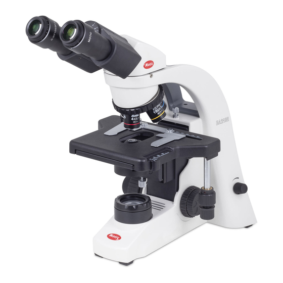
Page 9: Nomenclature
1. NOMENCLATURE BA210E (Binocular) - Page 10 BA210E (Binocular)
-
Page 11: Setting Up The Instrument
2. SETTING UP THE INSTRUMENT Avoid placing the instrument in locations exposed to direct sunlight, dust, vibration, high temperature and high humidity and where it is difficult to unplug the power supply cord. 2.1 Operating environment Indoor use Altitude: Max 2000 meters ... -
Page 12: Assembling The Microscope
3. ASSEMBLING THE MICROSCOPE 3.1 Verifying input voltage The automatic voltage selection works with a broad range of settings. However, always use a ower cord that is rated for the voltage used in your area and that has been approved to meet local safety standards. -
Page 13: Reckless Stage
3.3 Reckless stage Remove specimen holder for fast hand scanning of slides. Left hand operation stages is available for option. It should be used with the short stage knob for avoiding to interfere the fine focus knob.. 3.4 Specimen holder ... -
Page 14: Filters
(Fig.1) (Fig.2) 3.9 Filters Remove the collector cover and place the filter in the filter holder located around the field lens, screw the collector cover, taking care that dust, dirt and fingerprints do not get on the filter and the field lens. -
Page 15: Usage Of Microscope Components
4. USAGE OF MICROSCOPE COMPONENTS 4.1 Coarse and fine focusing (Fig.3) Focusing is carried out with the coarse and fine focus knobs at the left and right of the microscope stand. The direction of vertical movement of the stage corresponds to the turning direction of the focus knobs. -
Page 16: Stage Upper Limit Stop Adjustment
4.3 Stage upper limit stop adjustment (Fig.5) (Upper Stage Limit is preset at the factory; please only adjust if necessary) The Stage Upper Limit stop marks the stage position at which the specimen is in focus i.e. by restricting the movement of the coarse focus knob. ... -
Page 17: Diopter Adjustment
4.6 Diopter adjustment Diopter adjustment compensates for the differences in vision between the left and right eyes. In addition to making observation through both eyes easier, this adjustment also reduces the extent to which focusing is lost when the objective magnification is changed. In particular, this occurs when a low magnification objective is used. -
Page 18: Use Of Aperture Diaphragm
4.8 Use of aperture diaphragm The condenser aperture diaphragm is provided for adjusting the numerical aperture (N.A.) of the illuminating system of the microscope, it decides the resolution of the image, contrast, depth of focus and brightness. Stopping down will lower the resolution and brightness but increase the contrast and depth of focus. ... -
Page 19: Photomicrographic Procedure
5. PHOTOMICROGRAPHIC PROCEDURE To ensure vibration free operation, set the microscope on a sturdy vibration free table or a bench with a vibration proof device. Pull the optical path selection lever of the trinocular eyepiece tube all of the way out to the limit, the ratio of light entering the observation tube and phototube will be 20:80. -
Page 20: Using Oil Immersion Objectives
Oil immersion objectives are labelled with the additional engraving “Oil” and are to be immersed in oil between the specimen and the front of the objective. The immersion oil supplied by Motic is synthetic, non-fluorescing and non-resining oil, with a refractive index of 1.515 ... -
Page 21: Troubleshooting Table
7. TROUBLESHOOTING TABLE As you use your microscope, you may occasionally experience a problem. The troubleshooting table below contains the majority of frequently encountered problems and the possible causes. 7.1 Optical Problem Possible Cause Lamp not installed properly Condenser not mounted correctly Condenser is set too low Aperture diaphragm closed too far Vignetting or uneven brightness in the field of... -
Page 22: Electrical
Lamp voltage is set too low Image tinged yellow Blue filter is not being used Slide is upside down Focusing is not possible with high magnification objectives Cover glass is too thick Slide is upside down High magnification objectives strike the specimen when changing over from low to high Cover glass is too thick magnification... -
Page 23: Care And Maintenance
Store the objectives, eyepieces and filters in a container or desiccator with drying agent. Proper handling of the microscope will ensure years of trouble free service. If repair becomes necessary, please contact your Motic agency or our Technical Service direct. -
Page 24: Bulb Replacement
Note: If equipment is used in a manner not specified by the manufacturer, the warranty may be void. To avoid getting wet, do not use the microscope near water. 8.5 Bulb replacement The lamp and the lamphouse become very hot during and after a period of operation. Risk of burn –... -
Page 25: Led Module
Place microscope on its back and pull back the lamp house cover plate. (Fig.9) Firmly insert the LED module into the socket pinholes until it reaches the limit (Fig.10). This is a Motic patent design to exchange LED module and halogen bulb on the same socket directly. ... - Page 26 (Fig.11) (Fig.12)
-
Page 27: Warning Labels
Make sure the lamp has cooled sufficiently before attempting to replace the lamp. Don’t pick the microscope up from the bottom during equipment operation. Proper handling of the microscope will ensure years of trouble free service. If repair become necessary, please contact your Motic agency or our Technical Service directly.
Need help?
Do you have a question about the BA210E and is the answer not in the manual?
Questions and answers