Table of Contents
Advertisement
Quick Links
Advertisement
Table of Contents

Related Manuals for Motic BA310Met


Summary of Contents for Motic BA310Met
- Page 2 We are constantly endeavouring to improve our instruments and to adapt them to the requirements of modern research techniques and testing methods. This involves modification to the mechanical structure and optical design of our instruments. Therefore, all descriptions and illustrations in this instruction manual, including all specifications are subject to change without notice.
- Page 3 INFINITY OPTICAL SYSTEM An optical configuration (in which the specimen is located at the front focal plane of the objective) gathers light transmitted through or reflected from the central portion of the specimen and produces a parallel bundle of rays projected along the optical axis of the microscope toward the tube lens. A portion of the light reaching the objective originates from the periphery of the specimen, and enters the optical system at oblique angles, moving forward diagonally but still in parallel bundles toward the tube lens.
-
Page 4: Table Of Contents
1. Operating environment III. ASSEMBLING THE MICROSCOPE 1. Input voltage 2. Illumination 3. Stage 4. Objectives 5. Condenser for BA310Met-T 6. Eyepiece Tube 7. Eyepieces 8. Epi Illuminator 9. Filters for Epi Illuminator 10. Filters for transmitted illumination 11. Power Cord IV. - Page 5 9. Field Diaphragm of Epi-illuminator Centering 10. Aperture Diaphragm of Epi-illuminator Using 11. Centering the condenser for BA310Met-T 12. Use of aperture diaphragm for BA310Met-T 13. Use of field diaphragm for BA310Met-T 14. Brightness and Contrast Adjustment V. PHOTOMICROGRAPHIC PROCEDURE VI.
-
Page 6: Description
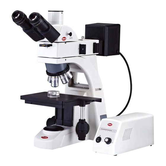
I. DESCRIPTION 1. Application: The Motic BA310Met and BA310Met-T are suitable for use in all areas of research and industry observing opaque material, e.g. in a. Metallography b. Mineralogy c. Mechanical engineering d. Electronics Except bright field observation, BA310Met and BA310Met-T are also used for polarized light observation. -
Page 7: Nomenclature
2. Nomenclature 2.1 BA310Met... -
Page 8: Ba310Met-T
2.2 BA310Met-T... -
Page 9: Epi Illuminator
2.3 Epi Illuminator... -
Page 10: Setting Up The Instrument
II. SETTING UP THE INSTRUMENT Avoid placing the instrument in locations exposed to direct sunlight, dust, vibration, high temperature, high humidity and where it is difficult to unplug the power supply cord. 1. Operating environment Indoor use Altitude: Max 2000 meters Ambient temperature: 5°C to 40°C ... -
Page 11: Illumination
And when a slide glass is used for observation of the specimen, an optional slideglass holder must be attached in place of the glass plate. The 6” x 4” stage comes with a glass plate as standard for BA310Met-T and a wafer holder is optional. 4. Objectives Lower the stage completely. -
Page 12: Condenser For Ba310Met-T
5. Condenser for BA310Met-T Raise the stage by turning the coarse focus knob. Completely lower the condenser carrier by turning the condenser focus knob. Insert the condenser into the dovetail mount with aperture scale facing forward towards the user. -
Page 13: Filters For Epi Illuminator
Plug the power cord from lamp house to the outlet on the rear panel of the microscope. (Fig.4) For the best image quality, install the Epi illuminator horizontally. 9. Filters for Epi illuminator Pull out the slider on Epi illuminator ... -
Page 14: Power Cord
Filter selection: Filter Function ND2 (T=50%) ND4 (T=25%) For brightness adjustment in photomicrography ND16 (T=6.25%) Blue filter (colour balance filter) For routine microscopy and photomicrography For phase contrast and contrast adjustment with Green interference (546nm) black and white film For colour photomicrography of HE stained HE (didymium filter) specimen with tungsten type film... -
Page 15: Microscopy
IV. MICROSCOPY 1. Illumination brightness adjustment Turn the brightness adjustment knob fully counterclockwise to the low brightness position. Set the power switch to “I” (ON). The green line control lamp in the switch must light up. The halogen lamp 12V/50 W in the Epi illuminator must light up. ... -
Page 16: Coarse Focus Torque Adjustment
3. Coarse focus torque adjustment To increase the torque, turn the torque adjustment ring (Fig.7) located behind the left-hand coarse focus knob in the direction indicated by the arrow. To reduce the torque, turn the ring in the direction opposite to that indicated by the arrow. (Fig.7) 4. -
Page 17: Beam Splitter Lever
5. Beam splitter lever The beam splitter lever of the trinocular eyepiece tube can be used to select the amount of light distributed between the trinocular eyepiece tube and the vertical phototube. When the lever is pushed in until it reaches the limit, 100% of the light enters the observation tube. When the lever is pulled out to the limit, the ratio of light entering the observation tube and phototube will be 20:80. -
Page 18: Polariser And Analyser Of Epi-Illuminator Using
(Fig.10) 8. Polariser and Analyser of Epi-illuminator using Insert the polariser (marked with “P”) into the front slot of Epi. Insert the Analyser (marked with “A”) into the side slot of Epi. Analyser is rotatable and the color of specimen with polarization will be changed when rotating. (Fig.11) 9. -
Page 19: Aperture Diaphragm Of Epi-Illuminator Using
(Fig.12) (Fig.13.a) (Fig.13.b) 10. Aperture diaphragm of Epi-illuminator using The condenser aperture diaphragm is provided for adjusting the numerical aperture (N.A.) of the illuminating system of the microscope, it decides the resolution of the image, contrast, depth of focus and brightness. ... -
Page 20: Centering The Condenser For Ba310Met-T
Adjust and centre the field diaphragm so that it is just outside the field of view for each magnification change. 12. Use of aperture diaphragm for BA310Met-T The condenser aperture diaphragm is provided for adjusting the numerical aperture (N.A.) of the illuminating system of the microscope, it decides the resolution of the image, contrast, depth of focus and brightness. -
Page 21: Use Of Field Diaphragm For Ba310Met-T
13. Use of field diaphragm for BA310Met-T The field diaphragm determines the illuminated area on the specimen. For normal observation, the diaphragm is set slightly larger than the field of view. If the illuminated area is set much larger than the field of view extraneous light will enter the field of view. -
Page 22: Photomicrographic Procedure
V. PHOTOMICROGRAPHIC PROCEDURE To ensure vibration free operation, set the microscope on a sturdy vibration free table or a bench with a vibration proof device. Pull the optical path selection lever of the trinocular eyepiece tube all of the way out to the limit, the ratio of light entering the observation tube and phototube will be 20:80. -
Page 23: Troubleshooting Table
VI. TROUBLESHOOTING TABLE As you use your microscope, you may occasionally experience a problem. The troubleshooting table below contains the majority of frequently encountered problems and the possible causes. Optical Problem Possible Cause Lamp not installed properly Condenser not mounted correctly Condenser is set too low Vignetting or uneven brightness in the field of Aperture diaphragm closed too far... -
Page 24: Electrical
Lamp voltage is set too low Image tinged yellow Blue filter is not being used Focusing is not possible with high magnification Slide is upside down objectives Cover glass is too thick High magnification objectives strike the Slide is upside down specimen when changing over from low to high Cover glass is too thick magnification... -
Page 25: Care And Maintenance
Never attempt to dismantle any parts other than described in this manual. If you notice any malfunction, contact your nearest Motic representative. 2. Cleaning the Microscope A. Lenses and filters ... -
Page 26: Bulb Replacement
3. Bulb Replacement To avoid potential shock hazard, always set the power switch to “O” (OFF) and disconnect the power cord before replacing the bulb. The bulb, lamp housing and areas near these will be extremely hot during and right after use. -
Page 27: 3W Led Module
B. 12V/ 3W LED Module This is a Motic patent design to exchange12V/ 3W LED module and 12V/ 50W halogen bulb on the same socket directly. Fully loosen the slotted head knurled screw on the back of the lamp house. -
Page 28: 3W Led Module
Place microscope on its back and pull back the lamp house cover plate. (Fig.21) Firmly insert the LED module into the socket pinholes until it reaches the limit (Fig.22). This is a Motic patent design to exchange LED module and halogen bulb on the same socket directly. ... -
Page 29: Disinfecting The Microscope
Proper handling of the microscope will ensure years of trouble free service. If repair become necessary, please contact your Motic agency or our Technical Service direct. Note: If equipment is used in a manner not specified by the manufacturer, the protection provided by the equipment may be impaired. -
Page 30: Warning Labels
Indicates that the main switch is ON. Indicates that the main switch is OFF. Indicates alternating current. Proper handling of the microscope will ensure years of trouble free service. If repair become necessary, please contact your Motic agency or our Technical Service directly.
Need help?
Do you have a question about the BA310Met and is the answer not in the manual?
Questions and answers