Motic BA310 POL Instructions Manual
Polarizing microscope
Hide thumbs
Also See for BA310 POL:
- Instruction manual (30 pages) ,
- Instruction manual (20 pages) ,
- Instruction manual (17 pages)
Table of Contents
Advertisement
Quick Links
Advertisement
Table of Contents

Subscribe to Our Youtube Channel
Related Manuals for Motic BA310 POL


Summary of Contents for Motic BA310 POL
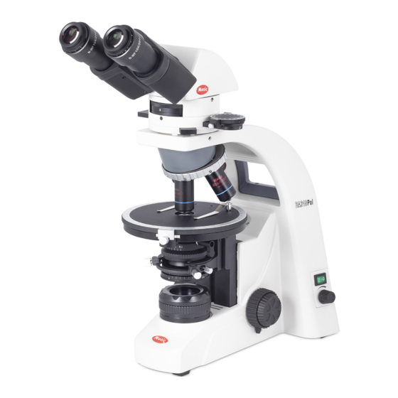
- Page 1 Polarizing Microscope BA310 POL Instructions...
- Page 2 We are constantly endeavouring to improve our instruments and to adapt them to the requirements of modern research techniques and testing methods. This involves modification to the mechanical structure and optical design of our instruments. Therefore, all descriptions and illustrations in this instruction manual, including all specifications are subject to change without notice.
- Page 3 Although every effort has been made to ensure the accuracy of this instruction manual, if you note any points that are unclear or inaccurate, please contact Motic agency or our Technical Service directly.
- Page 4 Introduction The polarizing microscope, or the petographic microscope, as it may be called, is used to the exclusion of models in the study of thin sections of minerals and rocks. The optical system is similar to that of the modern compound microscope. The polarizing microscope however, contains several additional features, which greatly increase its range of usefulness.
-
Page 5: Table Of Contents
TABLE OF CONTENTS SECTION PAGE NOMENCLATURE SETTING UP THE INSTRUMENT ASSEMBLING THE MICROSCOPE Input Voltage................11 Lamp and Lamp Cover House (Replacing the Lamp) ....... 11 Halogen Lamp ................11 Specimen Clip ................11 Attachable Mechanical Stage (Optional) ........11 Objectives ................. - Page 6 TABLE OF CONTENTS SECTION PAGE USING OIL IMMERSION OBJECTIVE PHOTOMICROGRAPHIC PROCEDURE ACCESSORIES TERMINOLOGY TROUBLESHOOTING TABLE CARE AND MAINTENANCE...
-
Page 7: Nomenclature
1 Nomenclature BA310 POL Eyepiece Diopter Adjustment Ring Binocular Eyepiece Tube Intermediate Tube Binocular Tube Clamp Screw Analyser Rotating Dial Analyser Slider Analyser Clamp Screw Intermediate Tube Clamp Screw Coarse Focus Height Stopper Revolving Nosepiece Circular Graduated Stage Condenser Aperture Scale... - Page 8 Compensator Slot Compensator Analyser Scale: 0 Analyser Rotating Dial Bertrand Lens Centering Screw Intermediate Tube...
- Page 9 Bertrand Lens Turret Bertrand Centering Screw Bertrand Lens Focus Ring Analyser Slider Knob Objective Centering Nosepiece Objective Centering Screws Objective Vernier Scale Polarizer Fine Focus Knob Coarse Focus Knob Sub-Stage (Condenser Carrier) Coarse Focus Torque Adjustment Ring Condenser Focus Knob BA310 POL...
- Page 10 Stage Clip Swing-Out Condenser Aperture diaphragm scale Aperture Diaphragm Ring Condenser Centering Screw Field Diaphragm Field Diaphragm Ring Condenser Top Lens Swing-Out Lever...
-
Page 11: Setting Up The Instrument
2 Setting up the Instrument Avoid placing the instrument in locations exposed to direct sunlight, dust, vibration, high temperature and high humidity 3 Assembling the Microscope Power Switch Brightness Control Knob Rating Label AC Input Voltage Input Voltage The automatic voltage selection works with a broad range of settings. However, always use a power cord that is rated for the voltage used in your area and that has been approved to meet local safety standards. -
Page 12: Input Voltage
Lamp and Lamp Cover (Replacing the Lamp) In order to prevent electric shock always turn the power switch off and unplug the power cord before installing or replacing the lamp. Place the microscope on its back and pull back the lamp cover plate. ... -
Page 13: Condenser
Condenser Raise the stage by turning the coarse focus knob. Lower the sub-stage (condenser carrier) by turning the condenser focus knob. Insert the dovetail mount with aperture scale facing the front. Secure with condenser clamp screw. ... -
Page 14: Eyepieces
3.12 Eyepieces Use the same magnification eyepieces for both the right and left eyes. Place the eyepieces into the sleeves of the binocular tube. The sleeve of the right eyepiece tube has positioning slots for either 90° and 45° orientation ... -
Page 15: Microscopy
4 Microscopy Manipulation of Each Component Coarse and Fine Focusing Focusing is carried out with the coarse and fine focus knobs at the left and right of the microscope stand. The direction of vertical movement of the stage corresponds to the turning direction of the focus knobs. -
Page 16: Binocular Tube
4.2. Binocular Tube I. Diopter Adjustment Diopter adjustment compensates for differences in vision between the left and right eyes. In addition to making observation through both eyes easier, this adjustment also reduces the extent to which focusing is lost when the objective magnification is changed. In particular, this occurs when a low magnification objective is used. -
Page 17: Condenser
Condenser I. Focusing and Centering Fully open the field of view diaphragm and condenser aperture diaphragm. Set the specimen on the stage with the cover glass facing up. Bring the specimen image into focus, using the 10X objective. ... -
Page 18: Field Diaphragm
In conoscopic microscopy: In conoscopic microscopy, the condenser aperture diaphragm works as a field diaphragm on the conoscopic image surface. Stop down the aperture diaphragm so it limits the periphery of the field of view of the conoscopic image. Field Diaphragm ... -
Page 19: Focusing And Centering The Bertrand Lens
Dark cross image is formed on the exit pupil of the objective Analyser rotating dial Analyzer clamp screw Rotate the Bertrand lens turret to “B” position and bring the Bertrand lens in the optical path to enable the exit pupil of the objective to be seen through the eyepiece. -
Page 20: Compensators
Bertrand Lens Centering Screws Bertrand Lens Turret Bertrand Lens Focus Ring Compensators All polarizing microscopes are fitted with a slot in the intermediate tube above the nosepiece and between the polarizer and analyzer. This is intended for insertion into the optical path of a compensator. ... - Page 21 Measuring Retardation from 1λ to 4λ Observing Extinction Position Observe the position where the part of the specimen to be ○ measured becomes darkest by rotating the stage under crossed polars. Observing Subtraction Position Rotate the stage 45º to the diagonal position where the specimen ○...
-
Page 22: Centering The Objectives
Centering the Objective The BA310 Polarizing microscope allows for centering of three objectives with a reference objective. Objective centering screws on the centering nosepiece are used to align the optical axis and the stage. Before centering the objectives, look through the binocular tube at the field of view, pick out an easily recognizable target and then rotate the stage. -
Page 23: Using Oil Immersion Objective
Oil immersion objectives are labelled with the additional engraving “Oil” and are immersed in oil between the specimen and the front of the objective. The immersion oil supplied by Motic is synthetic, non-fluorescing and non- resining oil, with a refractive index of 1.515 ... -
Page 24: Photomicrographic Procedure
6 Photomicrographic Procedure To ensure vibration free operation, set the microscope on a sturdy vibration free table or a bench with a vibration proof device. Pull the optical path selection lever of the trinocular eyepiece tube all the way out to the limit, the ratio of light entering the observation tube and phototube will be 20:80. -
Page 25: Accessories
7 Accessories Pinhole Stop Eyepiece tube insert with pinhole stop. Replace one of the eyepieces with an eyepiece tube insert with a pinhole stop. Remove the Bertrand lens out of the optical path and the conoscopic image can observed overlapping the orthoscopic image through the binocular observation. -
Page 26: Terminology
8 Terminology Aperture, Numerical (N.A.) Diaphragm, Condenser The numerical aperture is an important A diaphragm, which controls the effective factor determining the efficiency of the size of the condenser aperture. A condenser and objective. It is represented synonym for the condenser illuminating by the formula: aperture diaphragm. - Page 27 x-axis Crossed Polars In a plane Cartesian coordinate system, The condition in which the vibration the horizontal axis, or axis in the left to directions of polarizers and analysers are right direction. mutually perpendicular. y-axis Depolarizer In a plane Cartesian coordinate system, Depolarizers change plane polarization the vertical axis orthogonal to the x-axis.
-
Page 28: Troubleshooting Table
9 Troubleshooting Table As you use your microscope, you may occasionally experience a problem. The troubleshooting table below contains the majority of frequently encountered problems and the possible causes. Problem Possible Cause Analyser slider in intermediate position Compensator slider in midway position Bertrand lens in optical path Condenser not mounted correctly Condenser is not centred... - Page 29 Electrical Problem Possible Cause Power supply not plugged in Lamp does not light Lamp not installed Lamp burnt out Inadequate brightness Specified lamp not being used Lamp blows out immediately Specified lamp not being used Connectors are not securely connected Lamp flickers Lamp near end of service life Lamp not securely plugged into socket...
-
Page 30: Care And Maintenance
Store the objectives, eyepieces and filters in a container or desiccator with a drying agent. Proper handling of the microscope will ensure years of trouble free service. If repair become necessary, please contact your Motic agency or our Technical Service directly.
Need help?
Do you have a question about the BA310 POL and is the answer not in the manual?
Questions and answers