Table of Contents

Related Manuals for Motic BA410E Series


Summary of Contents for Motic BA410E Series
- Page 1 BA410E Series Biological Microscope Instruction Manual If the equipment is used in a manner not specified by the manufacturer, the protection provided by the Note equipment may be impaired. WWW.MOTIC.COM MOTIC INCORPORATION LTD.
- Page 2 We are constantly endeavouring to improve our instruments and to adapt them to the requirements of modern research techniques and testing methods. This involves modification to the mechanical structure and optical design of our instruments. Therefore, all descriptions and illustrations in this instruction manual, including all specifications are subject to change without notice.
- Page 3 Infinity corrected optics In this optical concept the light beams are parallel after leaving the objective in the direction of the eyepieces. A second optical element, the tube lens (normally located in the eyepiece tube) is used to converge the parallel beams, resulting in an intermediate image. The intermediate image is focussed by the eyepieces, to provide the real image for visual observation.
- Page 4 Microscope terminology Abbe Condenser Magnification A two-lens sub-stage condenser located below The number of times by which the size of the the stage of a microscope and functions to collect image exceeds the original object. Lateral light and direct it onto the object being examined. magnification is usually meant.
- Page 5 Diopter adjustment Resolving Power The adjustment of the eyepiece of an instrument A measure of an optical system's ability to to provide accommodation for the eyesight produce an image which separates two points or differences of individual observers. parallel lines on the object. Depth of Focus Resolution The axial depth of the space on both sides of the...
-
Page 6: Table Of Contents
Table of contents Section Page Nomenclature 1.1 Application 1.2 Nomenclature Setting up the instrument 2.1 Operating environment Assembling the microscope 3.1 Verifying Input voltage 3.2 Illumination 3.3 Rackless stage 3.4 Specimen holder 3.5 Objectives 3.6 Condenser 3.7 Eyepiece tube 3.8 Eyepieces 3.9 Filters 3.10 Power cord Usage of microscope components... - Page 7 4.13. IR function 4.14 Auto light intensity reproduction 4.15 Filters cassette Photomicrographic procedure Using oil immersion objective Troubleshooting table Care and maintenance 8.1. Do not disassemble 8.2 Cleaning the Microscope 8.3 Disinfecting the Microscope 8.4 When not in use 8.5 Bulb Replacement Warning labels...
-
Page 8: Nomenclature
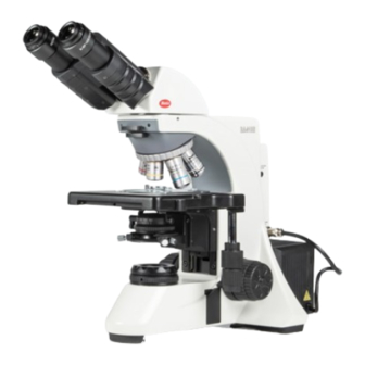
1. Nomenclature 1.1 Application Designed for multiple disciplines from University through clinical, laboratory, and research applications, the BA410E offers true professional quality with a full complement of accessories, making it a valued addition for any biological application. 1.2 Nomenclature BA410E-50W Halogen (Binocular) -
Page 9: Nomenclature
BA410E-50W Halogen (Binocular) - Page 10 BA410E-50W Halogen (Binocular)
-
Page 11: Setting Up The Instrument
2. Setting up the instrument Avoid placing the instrument in locations exposed to direct sunlight, dust, vibration, high temperature, high humidity and where it is difficult to unplug the power supply cord. 2.1 Operating environment Indoor use Altitude: Max 2000 meters ... -
Page 12: Assembling The Microscope
3. Assembling the microscope 3.1 Verifying Input voltage The automatic voltage selection works with a broad range of settings. However, always use a power cord that is rated for the voltage used in your area and that has been approved to meet local safety standards. -
Page 13: Rackless Stage
Loosen the round dovetail clamp screw on the microscope stand, insert the lamp house into the round dovetail on the microscope stand. Tighten the clap screw to secure the lamp house in place. The microscope can only use the lamp house provided by Motic. LED module 3.2.3 ... -
Page 14: Condenser
3.6 Condenser Raise the stage by turning the coarse focus knob. Completely lower the condenser carrier by turning the condenser focus knob. Insert the condenser into the dovetail mount with aperture scale facing to the user. Secure it with the condenser clamp screw. ... -
Page 15: Eyepieces
3.8 Eyepieces Use the same magnification eyepieces for both the eyes. Inserting or removing the eyepieces is facilitated by twisting the eyepieces (Fig.3a) when pushing in or pulling out (Fig.3b). Fig.3a Fig.3b 3.9 Filters Remove the collector cover (Fig.4a) and place the filter in the filter holder located around the field lens (Fig.4b), screw the collector cover (Fig.4a), taking care that dust, dirt and fingerprints do not get on the filter and the field lens. -
Page 16: Power Cord
Filter selection: Filter Function For brightness adjustment in photomicrography ND2 (T=50%) For routine microscopy and photomicrography Blue filter (colour balance filter) For phase contrast and contrast adjustment with black Green interference (546nm) and white film For colour photomicrography of HE stained specimen HE (didymium filter) with tungsten type film ... -
Page 17: Usage Of Microscope Components
4. Usage of microscope components 4.1 Coarse and fine focusing (Fig.5) Focusing is carried out with the coarse and fine focus knobs at the left and right of the microscope stand. The direction of vertical movement of the stage corresponds to the turning direction of the focus knobs. -
Page 18: Coarse Focus Quick Stop
4.3 Coarse Focus Quick Stop (Fig.7) The coarse focus quick stop serves as a quick accessible possibility for the user to limit the upper focus position in order to prevent a collision of the Objective with the specimen. Focus on the specimen using the lowest power objective and the coarse focus knob. -
Page 19: Using Thicker Samples
4.5 Using Thicker Samples Loose the screw (Fig.9a) Lower down the stage (Fig.9b) If the travel range is not enough for using, please remove the collector cover. Fig.9a Fig.9b 4.6 Beam Splitter Lever (Fig.10) When the beam splitter lever is pushed in, 100% of the light will enter the eyepieces. When pulled out, the light beam will be divided as follows: ... -
Page 20: Interpupillary Distance Adjustment
4.7 Interpupillary distance adjustment (Fig.11) Before adjusting the interpupillary distance, bring a specimen into focus using the 10x objective. Adjust the interpupillary distance so that both the right and left field of view become one. This adjustment will enable the user to observe the specimen with both eyes Fig.11 ... -
Page 21: Centering The Condenser
When the best focus position is reached, close this eye and use the other eye for the following steps. Correct the focus for the second eye by using only the Diopter Ring, do not use the coarse / fine focusing knob! ... -
Page 22: Use Of Aperture Diaphragm
4.10 Use of aperture diaphragm The condenser aperture diaphragm is provided for adjusting the numerical aperture (N.A.) of the illuminating system of the microscope, it decides the resolution of the image, contrast, depth of focus and brightness. Stopping down will lower the resolution and brightness but increase the contrast and depth of focus. -
Page 23: Brightness And Contrast Adjustment
4.12 Brightness and contrast adjustment Neutral density filters are used for brightness adjustment in routine microscopy and photomicrography. For phase contrast and contrast adjustment with black and white film, a Green interference filter (546nm) is recommended. An HE (didymium) filter for colour photomicrography, Haematoxylin, Eosin (HE) or Fuchsin stained specimen with tungsten type film is available. -
Page 24: Filters Cassette
4.15 Filters cassette Loose out the base plate screws and open the base plate (Fig.18a and Fig.18b) Move out the filter cassette cover (Fig.18c) Insert the filter cassette in the stand (Fig.18d and Fig.18e) Insert the filter slider in the filter cassette (Fig.18f) Fig.18a Fig.18b Fig.18c... -
Page 25: Photomicrographic Procedure
5. Photomicrographic procedure To ensure vibration free operation, set the microscope on a sturdy vibration free table or a bench with a vibration proof device. Pull the optical path selection lever of the trinocular eyepiece tube all of the way out to the limit. ... -
Page 26: Using Oil Immersion Objective
oil between the specimen and the front of the objective. The immersion oil supplied by Motic is synthetic, non-fluorescing and non-resining oil, with a refractive index of 1.515 Normally, cover glass must be used with oil immersion objectives with a few exceptions. -
Page 27: Troubleshooting Table
7. Troubleshooting table As you use your microscope, you may occasionally experience a problem. The troubleshooting table below contains the majority of frequently encountered problems and the possible causes. Optical Problem Possible Cause Bulb not installed properly Condenser not mounted correctly Condenser is not centred Condenser is set too low Condenser top lens not fully swung in/out... - Page 28 Dried stain or oil on objective lens. Lens must be removed from the microscope and examined with a Poor image (low contrast or resolution) magnifier (an inverted eyepiece can be used) to check for dirt Stage installed on inclined plane Specimen holder not fixed securely on stage Specimen not secured in position Uneven focus...
-
Page 29: Care And Maintenance
Proper handling of the microscope will ensure years of trouble free service. If repair becomes necessary, please contact your Motic agency or our Technical Service direct. Note: If equipment is used in a manner not specified by the manufacturer, the warranty may be void. -
Page 30: Bulb Replacement
8.5 Bulb Replacement The bulb and the lamphouse become very hot during and after a period of operation. Risk of burn – Do not touch the bulb during or immediately after a period of operation. Make sure the bulb has cooled sufficiently before attempting to replace the lamp. In order to prevent electric shock always turn the power switch off and unplug the power cord before installing or replacing the lamp. - Page 31 8.5.2 3W LED module This is a Motic patented design to exchange LED module and halogen bulb on the same socket directly. (Fig.20b). 3W LED module is used for 50W lamp house only. Loosen the lamp housing cover clamp screw using a coin and remove the cover. (Fig.20a) ...
- Page 32 8.5.3 100W Halogen The applicable halogen bulbs are the 12V 100W HAL high-intensity bulb. (Osram, model: 64625 HLX) Loosen the lamp housing cover clamp screw (Fig.21a) and remove the cover (Fig.21b). When installing the bulb, do not touch the glass surface of the bulb with bare fingers. (Fig.21c) Doing so will cause fingerprints, grease, etc., to burn onto the bulb surface, reducing the illumination provided by the bulb.
-
Page 33: Warning Labels
Make sure the bulb has cooled sufficiently before attempting to replace the bulb. Don’t pick the microscope up from the bottom during equipment operation. Proper handling of the microscope will ensure years of trouble free service. If repair become necessary, please contact your Motic agency or our Technical Service directly. - Page 34 Tel: 86-0592-562 7866 | Fax: 86-0592-562 7855 © 2007-2013 Motic China Group Co. Ltd. All rights reserved. Motic is a registered trademark and service mark of Motic China Group Co., Ltd. Microsoft Windows logo is a registered trademark of Microsoft Corporation. All other trademarks are the property of their respective owners.
Need help?
Do you have a question about the BA410E Series and is the answer not in the manual?
Questions and answers