Table of Contents
Advertisement
Advertisement
Table of Contents

Subscribe to Our Youtube Channel
Related Manuals for Motic BA210


Summary of Contents for Motic BA210
- Page 1 Instructions Manual English Motic Incorporation Ltd. UL Listed Product E250223...
- Page 2 INFINITY OPTICAL SYSTEM CONVENTIONAL MICROSCOPE An optical configuration (in which the specimen is located at The conventional microscope has a two-stage magnification the front focal plane of the objective) gathers light transmitted system. There are two lens systems, the objective and the through or reflected from the central portion of the specimen eyepiece, mounted at opposite end of a body tube.
- Page 3 Y–axis Real Viewfield = Eyepiece Field of View /Objective Magnification The axis that is usually vertical in a two-dimensional coordinate For example BA210: system. In microscopy Y-axis of the specimen stages is consid- Eyepiece field of view = 20mm ered that which runs front to back.
- Page 4 We are constantly endeavouring to improve our instruments and to adapt them to the requirements of modern research techniques and testing methods. This involves modification to the mechanical structure and optical design of our instruments. Therefore, all descriptions and illustrations in this instruction manual, including all specifications are subject to change without notice.
-
Page 5: Table Of Contents
TABLE OF CONTENTS Page Section Nomenclature Setting Up The Instrument Assembling The Microscope Verifying Input Voltage Lamp And Lamp House Cover House (Replacing The Lamp) Illumination Mechanical Stage Specimen Holder Objectives Condenser Eyepiece Tube Eyepieces 3.10 Filters 3.11 Power Cord Microscopy, Manipulation Of Each Component Coarse And Fine Focusing Coarse Focus Torque Adjustment... -
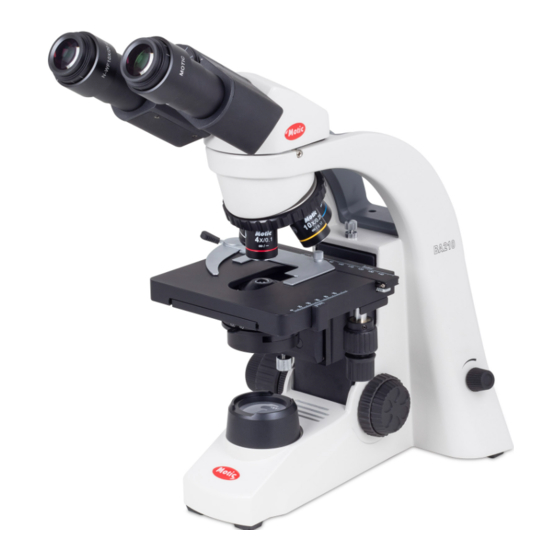
Page 6: Nomenclature
1. Nomenclature Eyepiece Interpupillary distance scale Diopter adjustment ring Eyepiece lock screw Binocular eyepiece tube Objective Specimen holder Stage Stage Y-Axis travel knob Condenser focus knob Stage X-Axis travel knob Field lens Fine focus knob Coarse focus knob Coarse focus torque adjustment ring... - Page 7 Optical Path Changeover lever Trinocular eyepiece tube Eyepiece tube Clamp Screw Revolving nosepiece Condenser Coarse focus height clamp screw stopper Condenser aperture lever Condenser Fine focus knob aperture scale Condenser Power switch position lock Brightness control knob Power input BA210 Trinocular...
-
Page 8: Setting Up The Instrument
2. Setting Up The Instrument 3. Assembling The Microscope 3.1. Verifying Input Voltage Avoid placing the instrument in locations exposed to direct sun- light, dust, vibration, high temperature and high humidity and where it is difficult to unplug the power supply cord. •... - Page 9 wipe it clean using lens tissue. 4. Loosen LED board locating ring, take away LED board • Close lamp house cover plate and secure until it snaps into locating ring. position. b. LED 1. Unscrew two hexagonal screws retaining the base plate. 5.
-
Page 10: Illumination
3.3. Illumination 3.8. Eyepiece Tube a. Halogen Lamp • Loosen the eyepiece clamp screw. Insert the round dovetail • The quartz halogen lamp, used as a light source, has higher mount on the eyepiece tube into the round dovetail mount on luminance and colour temperature than conventional tungsten the microscope arm. -
Page 11: Power Cord
4. Microscopy 4.1. Coarse And Fine Focusing • Filter selection: • Focusing is carried out with the coarse and fine focus knobs Filter Function at the left and right of the microscope stand. ND2 (T=50%) For brightness adjustment in photomicrography •... -
Page 12: Interpupillary Distance Adjustment
4.5. Interpupillary Distance Adjustment the specimen and the light source are said to be in the field plane. The condenser iris diaphragm controls the N.A. of the system, and is therefore said to be located in an aperture plane • Before adjusting the interpupillary distance, bring a specimen of the microscope. -
Page 13: Photomicrographic Procedure
• Pull the optical path selection lever of the trinocular eyepiece • The immersion oil supplied by Motic is synthetic, non-fluo- tube all of the way out to the limit, the ratio of light entering rescing and non-resining oil, with a refractive index of 1.515... -
Page 14: Troubleshooting Table
7. Troubleshooting Table As you use your microscope, you may occasionally experience a problem. The troubleshooting table below contains the majority of fre- quently encountered problems and the possible causes. Optical Problem Possible Cause Vignetting or uneven brightness in the field of view or Lamp not installed properly field of view only partially visible Condenser not mounted correctly... - Page 15 Problem Possible Cause No cohesion of binocular image Magnification or field of view of left and right eyepieces differ Interpupillary distance not adjusted Eyepiece diopter not adjusted Eye strain or fatigue Interpupillary distance not adjusted Diopter adjustment not made Field of view of left and right eyepiece differ Inadequate illumination Electrical Problem...
-
Page 16: Care And Maintenance
Make sure the lamp has cooled sufficiently before attempting • If repair become necessary, please contact your Motic agency to replace the lamp. or our Technical Service direct. Don’t pick up from the bottom during equipment operation. - Page 17 Canada | China | Germany | Spain | USA ® Motic Incorporation Ltd. (HONG KONG) * CCIS is a trademark of Motic Incorporation Ltd. Rm 2907-8, Windsor House, 311 Gloucester Road, Causeway Bay, Hong Kong Motic Incorporation Limited Copyright © 2002-2010.
Need help?
Do you have a question about the BA210 and is the answer not in the manual?
Questions and answers