Page 1
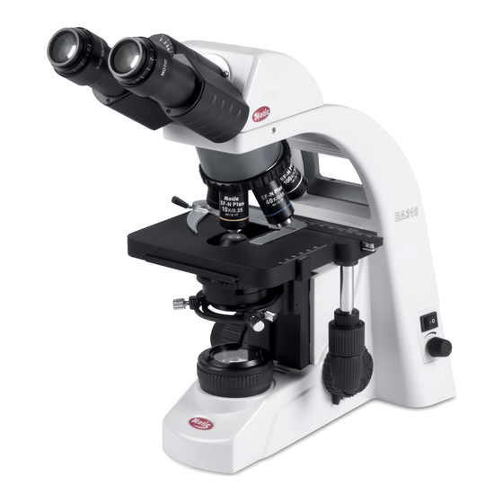
BA310/BA400/BA410 Multi Viewing System Instruction Manual MVH - 2 Two observers (Side Side) MVH - 3 Three observers (Side Side) MVH - 5 Five observers (Side Side for BA400/BA410 MVH - 2 Two observers (Face Face) WWW.MOTIC.COM MOTIC INCORPORATION LTD.
Page 2
To ensure correct usage, read this manual and the instruction manual specific to the microscope being utilized. We are constantly endeavouring to improve our instruments and to adapt them to the requirements of modern research techniques and testing methods. This involves modification to the mechanical structure and optical design of our instruments.
Table of Contents Nomenclature II. Assembly MVH – 2 Two observers (SideSide) MVH – 3 Three observers (SideSide) MVH – 5 Five observers (SideSide) MVH – 2 Two observers (FaceFace) III. Observation IV. Troubleshooting...
II. Assembly Assembly for MVH–2 Two observers (SideSide) The following drawing illustrates the configuration of the viewing attachment. ▲ ▲ Convey the image orientation of each field of view. This viewing head configuration does not allow the attachment of additional intermediate parts.
Page 9
Step 1. Main Observation Head Install the main observation head with the arrow control knob facing the main user. Fasten with the clamp screw located on the right hand side of the microscope arm. Step 2. Sub-Observation Head Slot in the relay lens unit (with sub-observation head attached) into the relay lens opening on the main head.
Page 10
Step 3. Support Stand Adjust the height of the support stand to ensure the main head and the sub- observation head are horizontal when attached. Release the height adjustment clamp knob, and let the centre rod float up with the aid of the built-in spring.
Assembly for MVH–3 Three observers (SideSide) The following drawing illustrates the configuration of the viewing attachment. ▲ ▲ Convey the image orientation of each field of view. This viewing head configuration does not allow the attachment of additional intermediate parts. Tools Needed: Allen Hex Wrench provided with the Viewing Head.
Page 12
Step 1. Main Observation Head Please refer to Assembly instruction under MVH-2 Step 2. Sub-Observation Head Please refer to Assembly instruction under MVH-2 Step 3. Support Stand Please refer to Assembly instruction under MVH-2 Step 4. Binocular Tubes Sub-Observation Head Mount the Binocular tubes on the sub-observation head and fasten in position using the clamp screw.
Assembly for MVH–5 Five observers (SideSide) The following drawing illustrates the configuration of the viewing attachment. ▲ ▲ Convey the image orientation of each field of view. This viewing head configuration does not allow the attachment of additional intermediate parts. Tools Needed: Allen Hex Wrench provided with the Viewing Head.
Page 14
Step 1. Main Observation Head Please refer to Assembly instruction under MVH-2 Step 2. Sub-Observation Head Slot in the relay lens unit (with sub-observation head attached) into the relay lens opening on either side of the main head. Secure with the relay lens unit clamping ring.
Step 6. Input Plug for the Arrow Illuminator Please refer to Assembly instruction under MVH-2 Step 7. AC Adapter Please refer to Assembly instruction under MVH-2 Assembly for MVH–2 Two observers (Face Face) Tools Needed: Allen Hex Wrench provided with the Viewing Head. Steps in Assembly Process: Step 1.
Page 16
Step 2. Support Stand Please refer to Assembly instruction under MVH-2 Step 3. Binocular Tubes Sub-Observation Head Mount the Binocular tubes on the sub-observation heads and fasten in position using the clamp screw. Step 4. Trinocular / Binocular Tube Main Observation Head Mount the Trinocular / Binocular eyepiece tube on the Main observation head and fasten it in position using clamp screw.
Page 17
Remove the battery cover by partially unscrewing the knurled thumb screws with a coin or screwdriver. Motic instructions for replacing the new batteries may be slightly different than the instructions provided by the manufacturer of the batteries. When in doubt, contact your local Motic representative for assistance.
III. Observation The sub-head observer will view the same image as the main observer if the main observer has adjusted the diopter settings according to the microscope instruction manual. Diopter adjustment Project the arrow into the field of view. ...
The pointer colour switch is in pointer is used. intermediate position. The arrow is not visible when Allow the battery to charge pointer is used. overnight. This manual may not be reproduced or transmitted in whole or in part without Motic’s express permission.
Page 20
Fax: 86-0592-562 7855 2007-2008 Motic China Group Co., Ltd. All rights reserved. Motic is a registered trademark and service mark of Motic China Group Co., Ltd. Microsoft Windows logo is a registered trademark of Microsoft Corporation. All other trademarks are the property of their respective owners.
Need help?
Do you have a question about the BA310 and is the answer not in the manual?
Questions and answers